
How to Build a Simple TCP Server on ESP32 with W5500?
This project shows how to connect an ESP32 to a WIZnet W5500 and use it as a wired TCP server in the Arduino environment.
How to Build a Simple TCP Server on ESP32 with W5500?
Summary
This project shows how to connect an ESP32 to a WIZnet W5500 and use it as a wired TCP server in the Arduino environment. The educational value is in the full path from SPI wiring to firmware bring-up: selecting the SPI pins, initializing the Ethernet library, checking hardware and link status, assigning an IP address, and accepting a TCP client connection that can echo received data back to the host.
What the Project Does
The source is a practical ESP32 + W5500 example that turns the board into a simple TCP server. The ESP32 uses the Arduino Ethernet library over SPI, brings up the W5500 with a fixed IP address, starts an EthernetServer, waits for an incoming TCP client, prints received bytes to the serial console, and echoes them back to the connected client. The article also includes a small Python socket client for testing the server from a PC.
For education, this is useful because it exposes all the visible stages of a wired embedded network path. The learner sees physical SPI wiring first, then firmware initialization, then hardware detection and link-state checks, and finally the TCP application layer where a host connects and exchanges payload data with the ESP32 server. That makes it a straightforward entry point for understanding how W5500 becomes a usable Ethernet interface on a microcontroller.
Where WIZnet Fits
The exact WIZnet product here is the W5500. In this project it is the external Ethernet controller connected to the ESP32 over SPI. WIZnet documents W5500 as a hardwired TCP/IP Ethernet controller with integrated 10/100 MAC/PHY, 8 independent sockets, 32 KB internal buffer memory, and SPI support up to 80 MHz.
In this Arduino-based design, W5500 provides the wired Ethernet hardware endpoint while the ESP32 runs the application logic. The source code uses the Arduino Ethernet library rather than direct register programming, so the learner interacts with a familiar server/client API instead of raw W5500 socket registers. That is good for introductory education, because it reduces bring-up complexity and keeps attention on firmware flow and basic TCP behavior.
One important limitation is that this article is not a deep network-stack study. It is a working example of board wiring, library-based initialization, and a minimal TCP server application. So the strongest lessons are in hardware hookup and firmware sequence, not in protocol internals or low-level socket state analysis.
Implementation Notes
A complete repository with verified file paths is not provided in the article, so exact source-tree paths cannot be cited. This is a blog example with embedded code snippets, and the safest reading is as a practical integration note rather than a reusable production repository.
The article gives a concrete wiring map for the SPI connection:
- MISO → IO19
- MOSI → IO23
- SCLK → IO18
- CS → IO26
- 3V3 → 3V3
- GND → GND
That matters because the firmware later uses Ethernet.init(26);, which ties the software chip-select configuration directly to the wiring table in the article. If the CS pin does not match, the rest of the initialization flow will fail even if power and SPI lines are correct.
The core bring-up sequence is also explicit in the example:
#include <Ethernet.h>
IPAddress serverIP(192, 168, 0, 144);
uint16_t serverPort = 8552;
byte mac[] = {0xDE, 0xAD, 0xBE, 0xEF, 0xFE, 0xED};
EthernetServer server(serverPort);
void setup() {
Ethernet.init(26);
Serial.begin(115200);
delay(2000);
Ethernet.begin(mac, serverIP);
delay(1000);
This snippet matters because it shows the real firmware order: configure chip select, start serial output for debugging, initialize the Ethernet stack with MAC and IP information, then proceed to status checks and server startup. For beginners, that sequence is more important than the individual API names.
The article then validates the hardware path using Ethernet.hardwareStatus() and Ethernet.linkStatus(), printing whether W5500 is detected and whether the physical link is up. That is a useful educational step because it separates hardware bring-up from application-level TCP debugging. If hardware detection fails or the link is off, the server logic is not the first thing to inspect.
Finally, the server loop accepts an EthernetClient, sends a greeting, reads incoming bytes, and echoes them back. A Python test client connects to 192.168.0.144:8552, sends "Hello ESP32 Server!", and prints the received reply. That gives the learner a complete test chain from embedded server to desktop client.
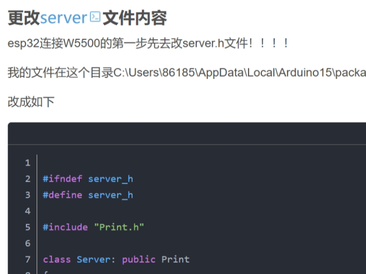
One caveat in the source should be treated carefully: the author modifies server.h inside the installed ESP32 Arduino core and notes that Wi-Fi stops working afterward. That is real evidence from the article, but it also means the approach is brittle and not a clean production integration method. For education it is a useful warning: a working demo can still rely on invasive framework changes that are unsuitable for maintainable products.
Practical Tips / Pitfalls
- Keep the SPI chip-select pin consistent between wiring and firmware. This example wires CS to IO26 and also calls
Ethernet.init(26). - Check
Ethernet.hardwareStatus()andEthernet.linkStatus()before debugging the TCP server logic. That separates wiring and PHY problems from application bugs. - Treat the fixed IP address as part of the lab setup. The example uses
192.168.0.144, so the PC test client and the router or local subnet must match that addressing plan. - Be cautious about editing Arduino core files. The article changes
server.hunder the ESP32 package and explicitly says Wi-Fi no longer works afterward. That is acceptable as a temporary experiment, not as a clean long-term design. - Remember that W5500 is an SPI Ethernet controller, so power integrity and cabling still matter even when the library hides most low-level details. WIZnet’s documentation still applies to the hardware underneath the Arduino API.
- This example teaches a minimal TCP path, not full protocol architecture. It is good for bring-up and first connectivity tests, but not enough by itself for advanced socket lifecycle or production error handling.
FAQ
Q: Why use W5500 in this ESP32 project?
A: Because W5500 gives the ESP32 a wired Ethernet interface over SPI without requiring the learner to design a full Ethernet subsystem from scratch. In this project it serves as the hardware network endpoint beneath the Arduino Ethernet API, which makes a first TCP server easier to build and test.
Q: How does W5500 connect to the ESP32?
A: In the article it connects over SPI with MISO on IO19, MOSI on IO23, SCLK on IO18, and CS on IO26, plus 3.3 V power and ground. The firmware mirrors that by calling Ethernet.init(26) for chip select.
Q: What role does W5500 play in this specific project?
A: It is the wired Ethernet controller that allows the ESP32 to host a TCP server. The ESP32 runs the server application logic, while W5500 provides the physical Ethernet interface and the lower-level network hardware path.
Q: Can beginners follow this project?
A: Yes, with some caution. The wiring and firmware flow are simple enough for education, but the article also relies on editing an ESP32 Arduino core header, which is not beginner-friendly as a general practice. It is best treated as a lab exercise rather than a polished reference design.
Q: How does this compare with using ESP32 Wi-Fi instead?
A: This example uses W5500 to provide a wired Ethernet path, which is useful when you want stable physical connectivity and a direct cable-based lab setup. The article itself also notes that its core modification breaks Wi-Fi support, so in this specific experiment the design is clearly focused on Ethernet rather than dual-interface coexistence.
Source
Original source: CSDN article “ESP32 连接W5500 TCP收发数据,” published November 10, 2024, with CC BY-SA 4.0 noted on the page.
Supporting references: WIZnet W5500 official documentation, ESP-IDF Ethernet programming guide, and Espressif’s W5500 component reference.
Tags
#W5500 #ESP32 #Arduino #Ethernet #TCPServer #SPI #EmbeddedNetworking #FirmwareFlow #HardwareWiring #Education
ESP32에서 W5500으로 간단한 TCP 서버를 어떻게 구축할 수 있을까?
Summary
이 프로젝트는 ESP32를 WIZnet W5500에 연결하고, Arduino 환경에서 이를 유선 TCP 서버로 사용하는 방법을 보여줍니다. 교육적인 가치는 SPI 배선부터 펌웨어 bring-up까지 전체 흐름이 드러난다는 점에 있습니다. SPI 핀 선택, Ethernet 라이브러리 초기화, 하드웨어 및 링크 상태 확인, IP 주소 설정, 그리고 호스트와 TCP 클라이언트 연결을 맺어 수신 데이터를 다시 되돌려 보내는 과정까지 포함합니다.
What the Project Does
이 소스는 ESP32 + W5500 조합을 간단한 TCP 서버로 동작시키는 실용 예제입니다. ESP32는 Arduino Ethernet 라이브러리를 SPI 위에서 사용하고, 고정 IP로 W5500을 bring-up한 뒤, EthernetServer를 시작하고, 들어오는 TCP 클라이언트를 기다립니다. 이후 수신한 바이트를 시리얼 콘솔에 출력하고, 다시 클라이언트로 echo합니다. 글에는 PC에서 서버를 테스트하기 위한 간단한 Python socket 클라이언트도 포함되어 있습니다.
교육 관점에서 이 예제가 좋은 이유는 유선 임베디드 네트워크 경로의 모든 가시적인 단계를 보여주기 때문입니다. 학습자는 먼저 물리적 SPI 배선을 보고, 그다음 펌웨어 초기화 과정을 이해하고, 이후 하드웨어 감지와 링크 상태 확인을 거쳐, 마지막으로 호스트가 접속해 ESP32 서버와 payload를 주고받는 TCP 애플리케이션 계층까지 확인할 수 있습니다. 즉 W5500이 마이크로컨트롤러에서 실제 Ethernet 인터페이스로 어떻게 쓰이는지 입문용으로 이해하기 좋은 구조입니다.
Where WIZnet Fits
이 프로젝트에서 사용된 정확한 WIZnet 제품은 W5500입니다. 이 설계에서 W5500은 ESP32에 SPI로 연결되는 외부 Ethernet controller입니다. WIZnet 공식 문서에 따르면 W5500은 hardwired TCP/IP Ethernet controller이며, 통합 10/100 MAC/PHY, 8개의 독립 소켓, 32 KB 내부 버퍼 메모리, 최대 80 MHz SPI를 제공합니다.
이 Arduino 기반 설계에서 W5500은 유선 Ethernet 하드웨어 endpoint를 제공하고, ESP32는 애플리케이션 로직을 담당합니다. 원문 코드는 직접 레지스터를 다루지 않고 Arduino Ethernet 라이브러리를 사용하므로, 학습자는 raw W5500 socket register 대신 익숙한 server/client API를 다루게 됩니다. 교육 초반에는 이 방식이 적절합니다. bring-up 복잡도를 낮추고, 펌웨어 흐름과 기본 TCP 동작에 집중할 수 있기 때문입니다.
다만 이 글은 깊이 있는 네트워크 스택 분석 자료는 아닙니다. 실제 강점은 하드웨어 연결, 라이브러리 기반 초기화, 그리고 최소 TCP 서버 애플리케이션 예제에 있습니다. 따라서 가장 강한 학습 포인트는 프로토콜 내부보다는 배선과 펌웨어 순서에 있습니다.
Implementation Notes
완전한 저장소와 검증 가능한 파일 경로가 제공된 것은 아니므로, 정확한 소스 트리 경로를 인용할 수는 없습니다. 이 자료는 코드 스니펫이 포함된 블로그 예제이며, 재사용 가능한 production repository라기보다 실용적인 통합 노트로 보는 편이 안전합니다.
글은 SPI 연결에 대한 구체적인 배선 맵을 제시합니다.
- MISO → IO19
- MOSI → IO23
- SCLK → IO18
- CS → IO26
- 3V3 → 3V3
- GND → GND
이 부분이 중요한 이유는 이후 펌웨어에서 Ethernet.init(26);를 호출하기 때문입니다. 즉 소프트웨어의 chip-select 설정이 글의 배선표와 직접 연결됩니다. CS 핀이 다르면 전원과 SPI 라인이 맞아도 나머지 초기화 흐름은 실패합니다.
핵심 bring-up 순서도 예제 안에 분명히 드러납니다.
#include <Ethernet.h>
IPAddress serverIP(192, 168, 0, 144);
uint16_t serverPort = 8552;
byte mac[] = {0xDE, 0xAD, 0xBE, 0xEF, 0xFE, 0xED};
EthernetServer server(serverPort);
void setup() {
Ethernet.init(26);
Serial.begin(115200);
delay(2000);
Ethernet.begin(mac, serverIP);
delay(1000);
이 스니펫이 중요한 이유는 실제 펌웨어 순서를 잘 보여주기 때문입니다. chip select를 먼저 설정하고, 디버깅용 serial을 시작하고, MAC과 IP 정보로 Ethernet을 초기화한 뒤, 상태 확인과 서버 시작으로 넘어갑니다. 입문자에게는 개별 API 이름보다 이 순서 자체가 더 중요합니다.
원문은 이어서 Ethernet.hardwareStatus()와 Ethernet.linkStatus()로 W5500이 감지되었는지, 물리 링크가 살아 있는지를 출력합니다. 이 단계는 교육적으로 매우 유용합니다. 하드웨어 bring-up과 애플리케이션 수준의 TCP 디버깅을 분리해주기 때문입니다. 하드웨어 감지가 실패하거나 링크가 내려가 있다면, 먼저 서버 로직이 아니라 배선과 PHY 쪽을 봐야 합니다.
마지막으로 서버 루프는 EthernetClient를 받아 greeting을 보내고, 들어오는 바이트를 읽고, 이를 다시 echo합니다. Python 테스트 클라이언트는 192.168.0.144:8552로 접속해 "Hello ESP32 Server!"를 보내고, 응답을 출력합니다. 덕분에 학습자는 임베디드 서버부터 데스크톱 클라이언트까지 하나의 완전한 테스트 체인을 바로 확인할 수 있습니다.
한 가지 주의할 점도 있습니다. 작성자는 설치된 ESP32 Arduino core 내부의 server.h를 수정했고, 그 이후 Wi-Fi가 더 이상 동작하지 않는다고 적고 있습니다. 이것은 원문이 보여주는 실제 증거이지만, 동시에 이 접근이 취약하다는 뜻이기도 합니다. 교육용 데모로는 의미가 있지만, 유지보수 가능한 제품 설계 방식으로 보기에는 적절하지 않습니다.
Practical Tips / Pitfalls
- SPI chip-select 핀은 배선과 펌웨어에서 반드시 일치해야 합니다. 이 예제는 CS를 IO26에 연결하고
Ethernet.init(26)도 사용합니다. - TCP 서버 로직을 디버깅하기 전에
Ethernet.hardwareStatus()와Ethernet.linkStatus()를 먼저 확인해야 합니다. 그래야 배선/PHY 문제와 애플리케이션 문제를 구분할 수 있습니다. - 고정 IP 주소도 실험 환경의 일부입니다. 예제는
192.168.0.144를 사용하므로, PC 클라이언트와 라우터 또는 로컬 서브넷 설정이 이에 맞아야 합니다. - Arduino core 파일을 직접 수정하는 방식은 주의해야 합니다. 원문도
server.h수정 후 Wi-Fi가 동작하지 않는다고 밝히고 있습니다. 임시 실험에는 가능하지만 장기적인 설계 방식으로는 적절하지 않습니다. - W5500이 라이브러리 뒤에 가려져 있어도, 여전히 SPI Ethernet controller입니다. 따라서 전원 안정성, 배선 품질, 케이블 상태는 계속 중요합니다.
- 이 예제는 최소 TCP 경로를 보여주는 자료입니다. bring-up과 첫 연결 테스트에는 좋지만, 고급 socket lifecycle이나 production 수준 오류 처리까지 다루지는 않습니다.
FAQ
Q: 이 ESP32 프로젝트에서 왜 W5500을 사용하나요?
A: W5500은 ESP32에 SPI 기반 유선 Ethernet 인터페이스를 제공하기 때문입니다. 이 프로젝트에서는 Arduino Ethernet API 아래에서 하드웨어 네트워크 endpoint 역할을 하므로, 첫 TCP 서버를 더 쉽게 만들고 테스트할 수 있습니다.
Q: W5500은 ESP32에 어떻게 연결되나요?
A: 원문에서는 SPI로 연결하며, MISO는 IO19, MOSI는 IO23, SCLK는 IO18, CS는 IO26을 사용합니다. 펌웨어도 이에 맞춰 Ethernet.init(26)를 호출합니다.
Q: 이 프로젝트에서 W5500은 구체적으로 어떤 역할을 하나요?
A: W5500은 ESP32가 TCP 서버를 호스팅할 수 있도록 해주는 유선 Ethernet controller입니다. ESP32는 서버 애플리케이션 로직을 실행하고, W5500은 물리 Ethernet 인터페이스와 저수준 네트워크 경로를 담당합니다.
Q: 초보자도 따라갈 수 있나요?
A: 가능합니다. 다만 주의가 필요합니다. 배선과 펌웨어 흐름 자체는 교육용으로 충분히 단순하지만, 글에서 ESP32 Arduino core 헤더를 직접 수정하는 부분은 일반적인 초보자용 모범 사례는 아닙니다. 실습용 랩 예제로 보는 것이 적절합니다.
Q: ESP32 Wi-Fi를 쓰는 것과 비교하면 어떤가요?
A: 이 예제는 W5500을 사용해 유선 Ethernet 경로를 제공합니다. 케이블 기반의 안정적인 실험 환경이 필요할 때 유용합니다. 또한 원문은 핵심 수정 이후 Wi-Fi가 동작하지 않게 되었다고 밝히므로, 이 실험은 dual-interface 공존보다는 Ethernet 집중형 구조에 가깝습니다.
Source
Original source: CSDN article “ESP32 连接W5500 TCP收发数据,” published November 10, 2024.
License: CC BY-SA 4.0 noted on the page.
Supporting references: WIZnet W5500 official documentation, ESP-IDF Ethernet programming guide, and Espressif’s W5500 component reference.
Tags
#W5500 #ESP32 #Arduino #Ethernet #TCPServer #SPI #EmbeddedNetworking #FirmwareFlow #HardwareWiring #Education