
Cloud Camera(Raspberry Pi RP2040 + w5100s + POE) Part 1:Hardware
I want to develop a RP2040-based IP camera, and do application development based on the cloud platform.

Raspberry Pi - RP2040
x 1
WIZnet - W5100S
x 1
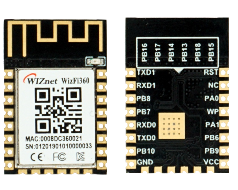
WIZnet - WizFi360
x 1
Altium Designer - Altium Designer
x 1

Arduino - Arduino IDE
x 1

Adafruit - Circuitpython
x 1
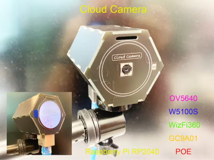
I want to develop a RP2040-based IP camera, and do application development based on the cloud platform. Because the entire development cycle will be relatively long, I will introduce the current development progress in this article, which is the hardware design part of this project. I will introduce the software code-related content in the software chapter.
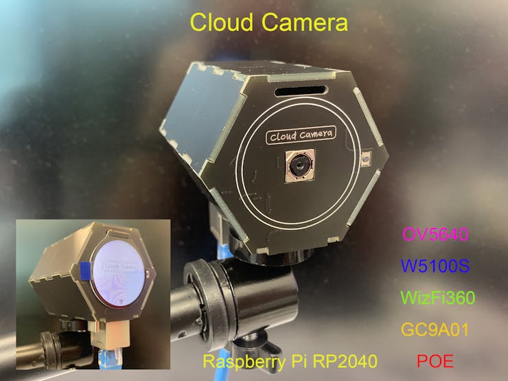
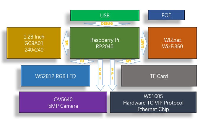
I named this project Cloud Camera, using Raspberry Pi's RP2040 as the MCU, using OV5640 as the camera for image acquisition, using W5100S as the Ethernet chip, integrating a WiFi module wizfi360, and has a TF card interface. In addition, this application uses The largest FLASH chip supported by RP2040 is M25Q128 (16MB), and integrates the POE module developed by me. The network cable supports both power supply and data transmission.

The hardware block diagram of the whole project is shown in the figure below:
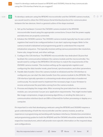
Before developing, I consulted Chatgpt for suggestions for my project, however:
Consistent with the style of the previous Cloud Pixel and Cloud Printer, I still use PCB as the material of the shell.
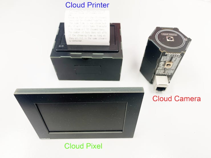
I have introduced the design of Cloud Pixel and Cloud Printer in previous articles, and you can get more information through the following links.
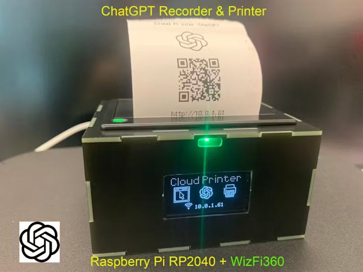
ChatGPT Recorder & printer (Cloud Printer)
Todolist Sync Monitor(Cloud Pixel)
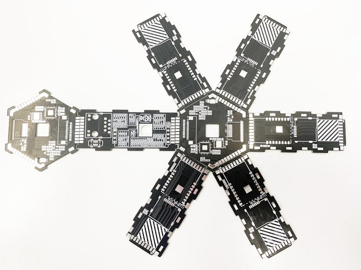
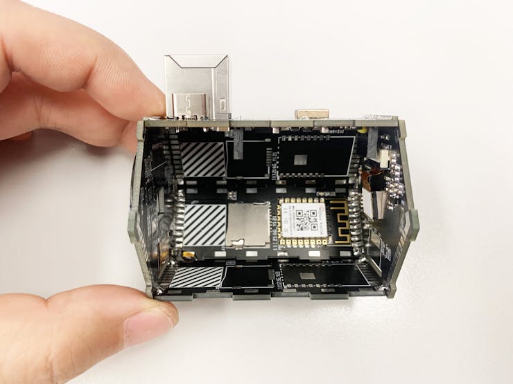
I arranged all the components on three PCBs, namely the main control PCB, the W5100S Ethernet PCB, and the WiFi PCB. They are combined according to the following structure to form a complete shell.
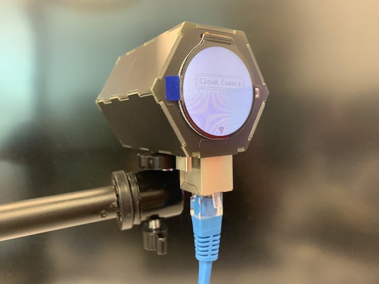
After the casing is assembled:
I will introduce three PCBs separately:
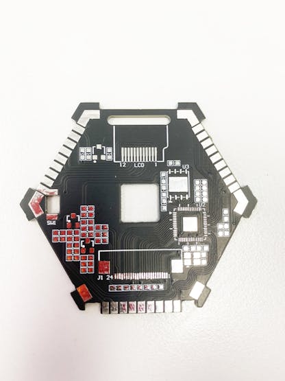
Main control PCB:
RP2040, screen (GC9A01), OV5640, etc. are arranged on this board. This PCB uses two pieces in the shell structure, which are used as the front board and the rear board respectively. When used as a front board, weld part of the circuit of RP2040 and part of the camera; when used as a rear board, only need to weld the relevant circuit of the screen and the shooting button;
23_vkJDRhJ4qc.jpg?auto=compress%2Cformat&w=740&h=555&fit=max)
Main control PCB
Act as front board:
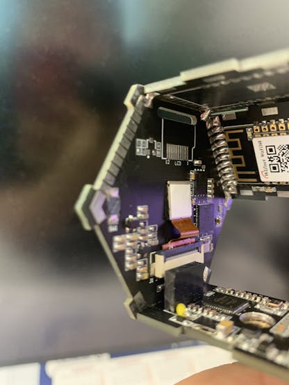
Act as rear board:
I arranged the circuit of the Ethernet part of the W5100S on this PCB, as well as the circuit powered by the USB interface. The POE part uses an additional module, which is an optional part through the connector. After the POE module is plugged in, it can communicate and supply power through the network cable.
Schematic diagram:
_aCDojMZnNN.jpg?auto=compress%2Cformat&w=740&h=555&fit=max)
PCB:
PCB(back):
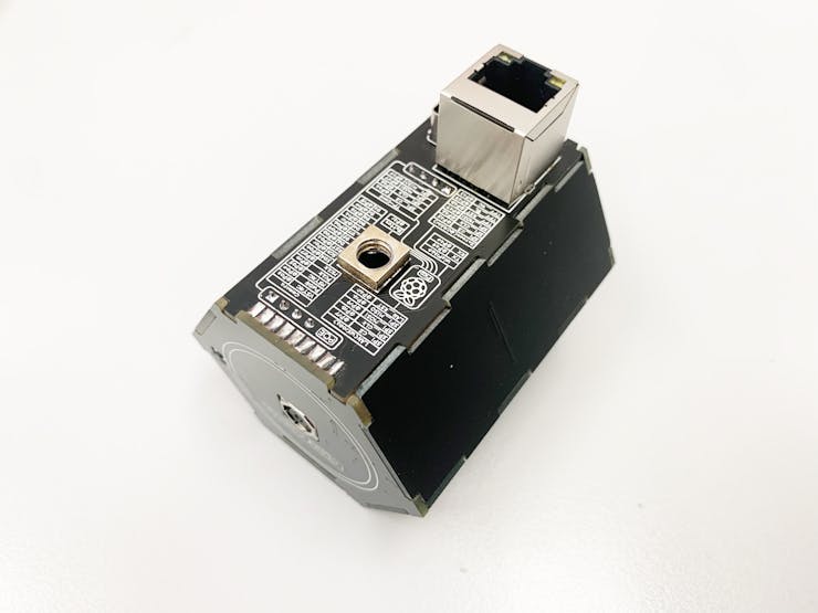
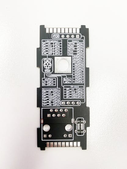
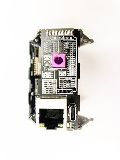
On the outward side of the Ethernet board, the IO definitions of all the interfaces used by the Cloud Camera are marked with silkscreen.
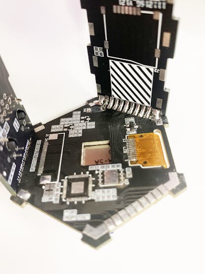
Connect the front board and Ethernet board by soldering:
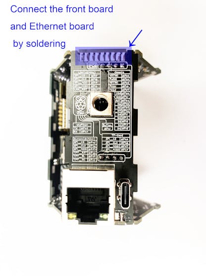
The DC-DC circuit on the POE board is set to 3.3v output.
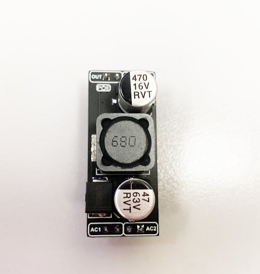
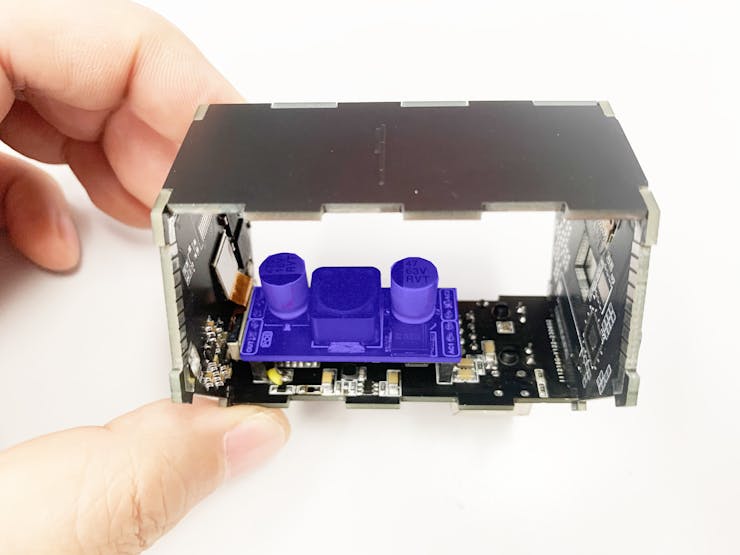
After plugging in the POE module.
The Ethernet board also has a USB interface circuit on board, and the USB interface can also supply power and debug this device:
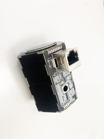
A screw interface can also be welded on it, which is compatible with the fixing screws of our camera.
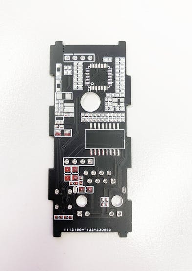
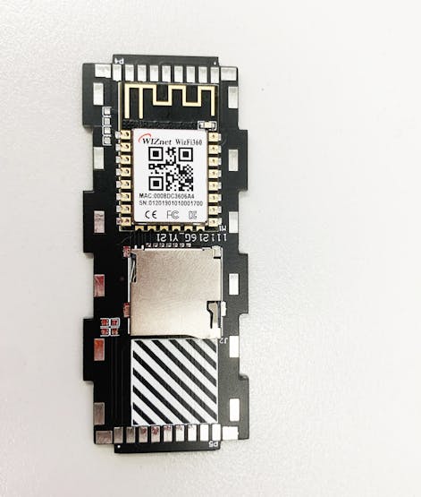
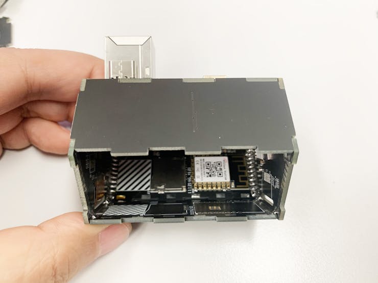
In fact, this board is mainly used as a cable to connect the front board and the rear board, but additional wizfi360 and TF interfaces are added, as long as one set is soldered at a specific position, the others are only used as the shell, without soldering any components.
Schematic diagram:
_xINTDQPPnr.jpg?auto=compress%2Cformat&w=740&h=555&fit=max)
PCB:
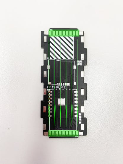
Connect the front board and the rear board through the two rows of pads in the above picture.
As shown in the figure below, solder the adjacent pads to complete the connection between the shells.
more board.
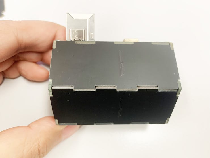
The shell is closed.
My idea is to use this Cloud Camera as an open source hardware development platform. This platform is equipped with an OV5640 camera and has access methods such as Ethernet and WiFi. Next, I will use this platform to develop some image processing applications. Image processing based on the public network API.

Hardware under testing.
Powered by POE.
-
Cloud Camer Main control PCB SCH

-
Cloud Camer WIFI PCB SCH
-
Cloud Camer Ethernet PCB SCH
-
SCH IN GITHUB


