
WizFi360 LED Controller Board
Hi,
I would like to make a WizFi360 LED controller PCB that can be controlled using a mobile application or using sensors & edge AI.
WIZnet - WizFi360
x 1

seeed - Grove - Relay
x 2
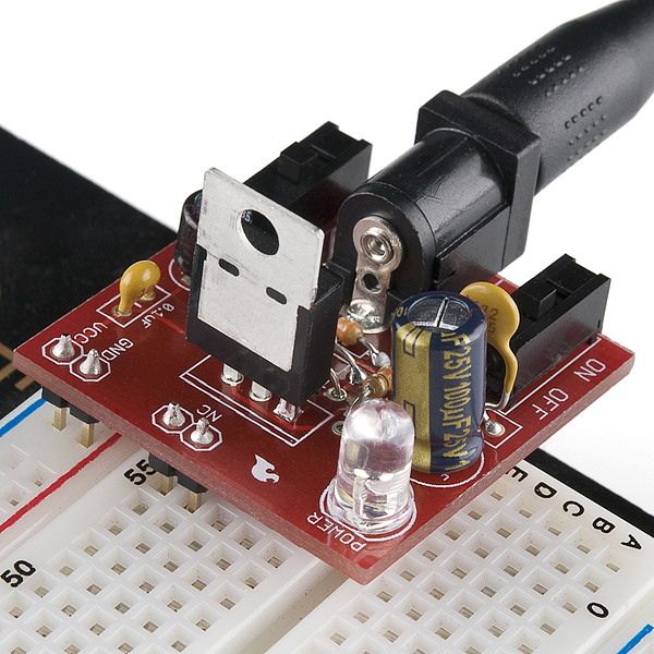
sparkfun - SparkFun Breadboard Power Supply 5V/3.3V
x 1

Arduino - Arduino IDE
x 1
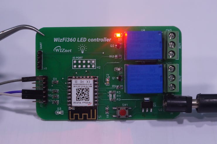
WizFi LED controller PCB
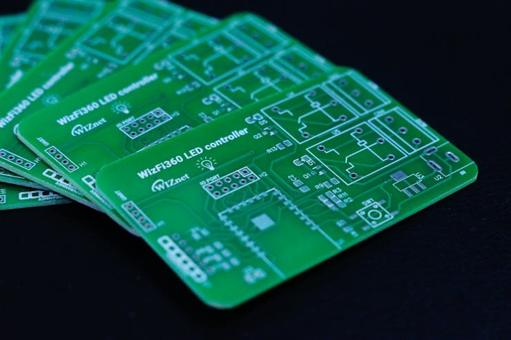
We will be making a LED controller using WizFi. We will be designing the PCB using easyeda. The generated Gerber files are fabricated them. Firmware for WizFi360 is also written.
Demo video
Hardware
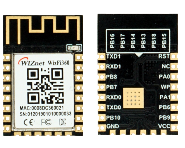
We received a WizFi360-PA module from Wiznet. WizFi360 is a low-cost Wi-Fi solution that not only is Azure Certified and supports AWS SDK examples, but also is the official Wi-Fi Shield for Arm Open-CMSIS-pack and Keil Studio Cloud; lastly, comes in a Raspberry Pi Pico compatible board form-factor

The Pin Definition is given below

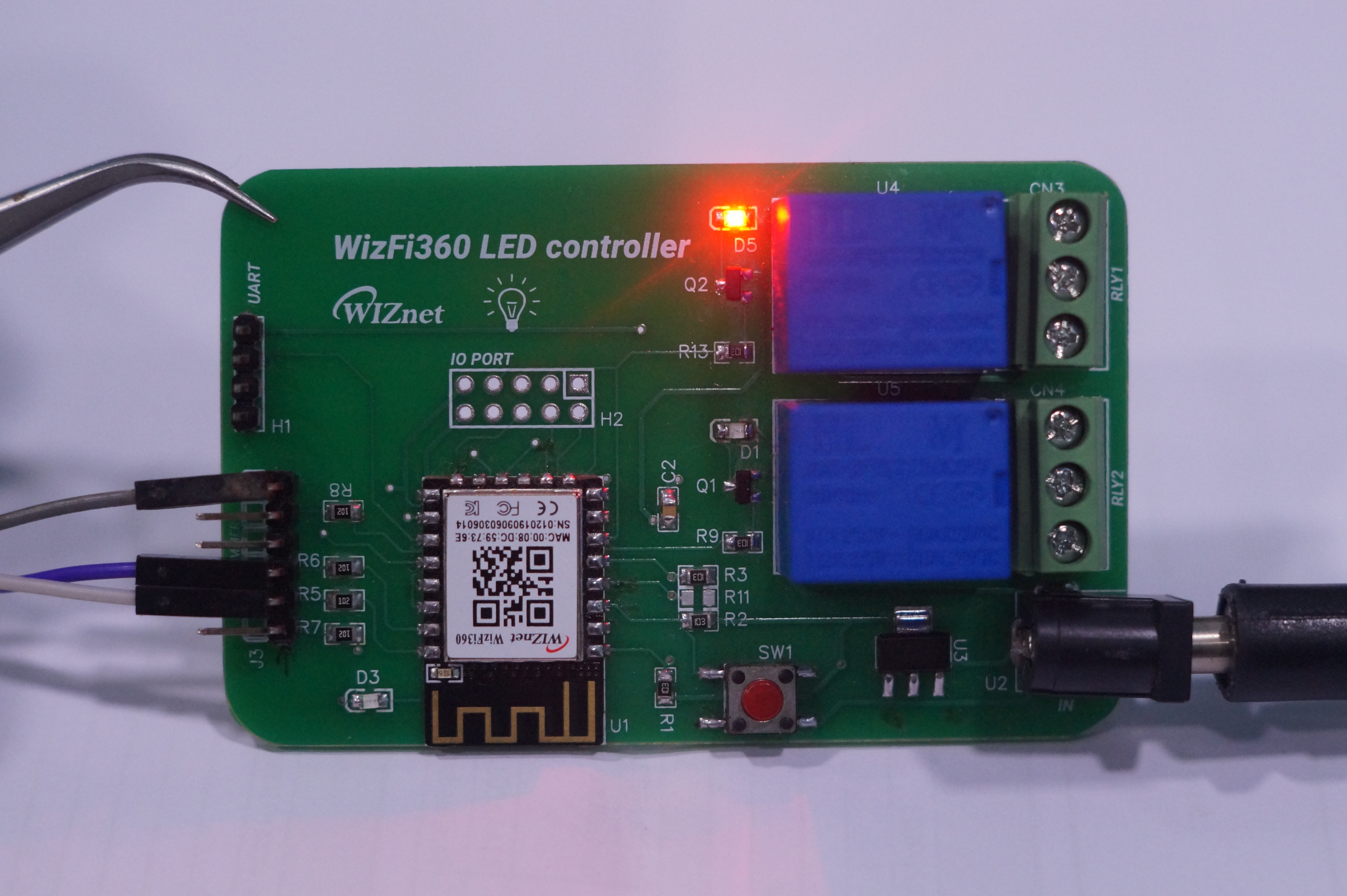
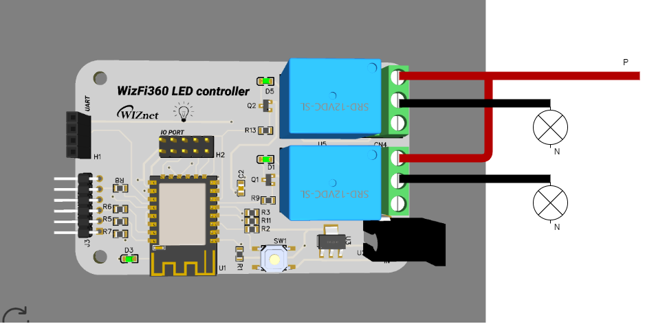
The WizFi360 is powered by the WizFi360-PA module. The relays are connected to the pins PB6 and PB8.

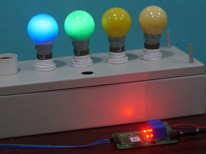
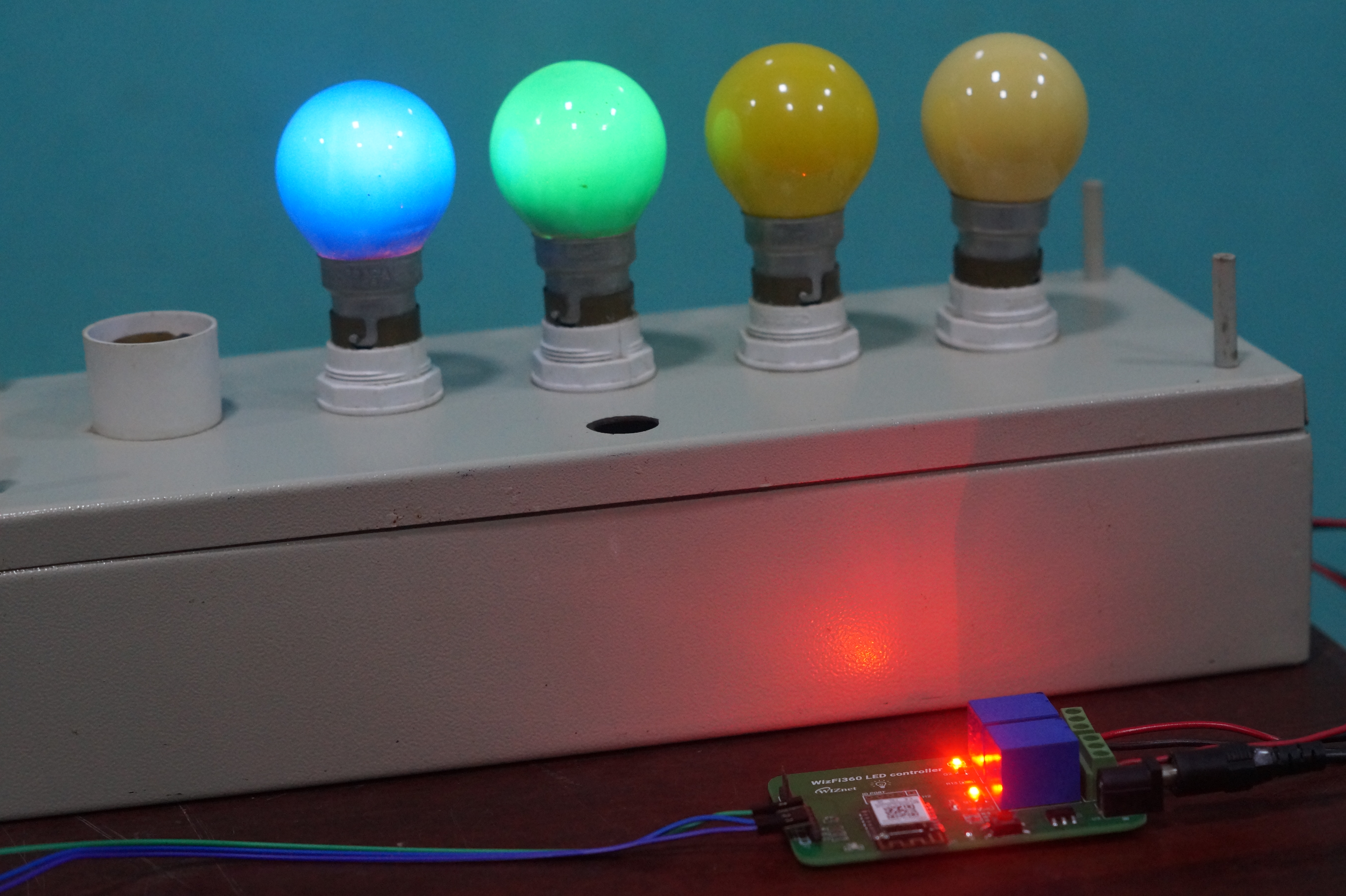
The electronic circuit is formed by a group of relay circuits that will be turned on/off using a mobile phone or using AT commands. This will be done by controlling the PB6 and PB8 pins.
Each led will be connected to the output port of the relays and will be connected to the circuit on the board through wires.
What logic was implemented?
The WizFi360 module makes use of AT commands to control the relay ports. The AT commands are sent to the module from a PC using a USB-to-Serial converter.

The relay is turned on and off by pulling the relay pin's HIGH or LOW.
- When PB6 is HIGH, Relay 1 output switches from NC to NO.
- When PB6 is LOW, Relay 1 output switches from NO to NC.
- When PB8 is HIGH, Relay 2 output switches from NC to NO.
- When PB8 is LOW, Relay 2 output switches from NO to NC.

Finally, we finalized the electronic schematic design and developed the layout of the printed circuit board. See the result in the figure below.

Two mounting holes were inserted in the electronic board to facilitate the fixing of the board to the desired place.
The following is the full 3D view of the board.

AT
AT+SYSIOSETCFG=6,1,0
AT+SYSIOGETCFG=6
AT+SYSGPIODIR=6,1 //DIR OUTPUT
AT+SYSGPIOWRITE=6,0 //OP OFF
AT+SYSGPIOWRITE=6,1 //OP ON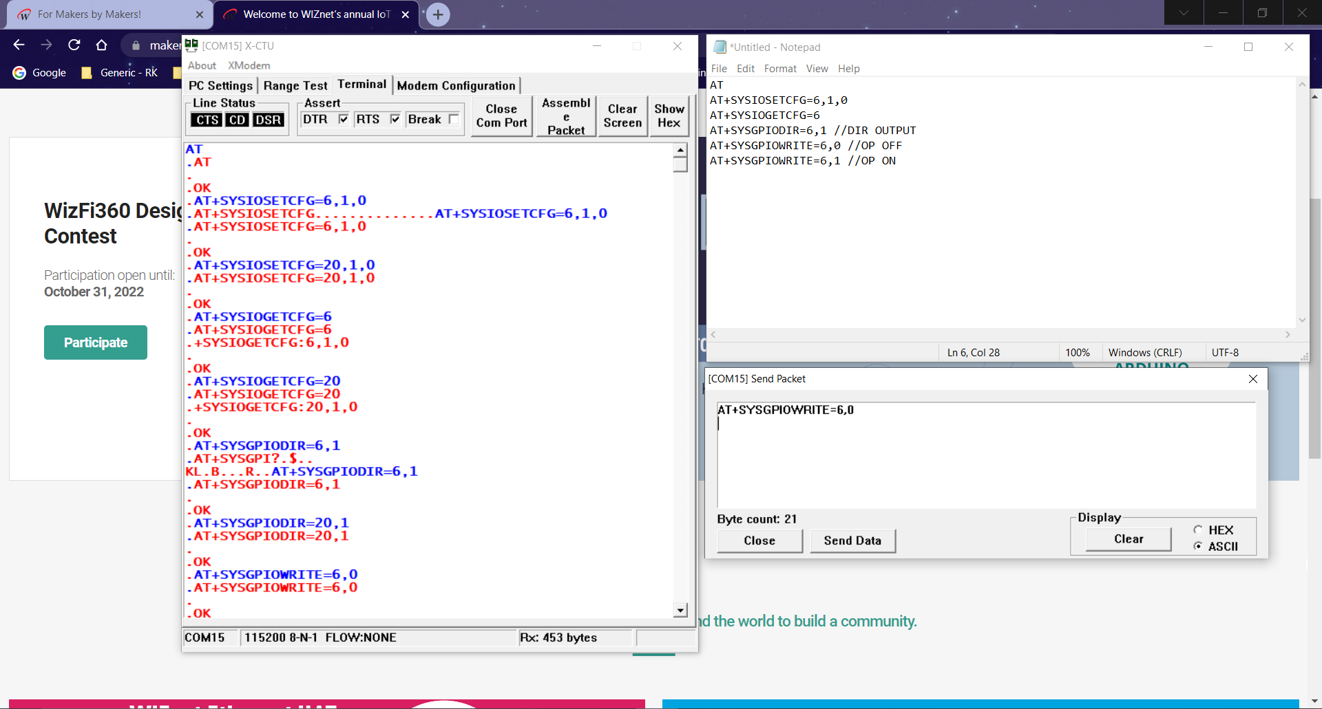
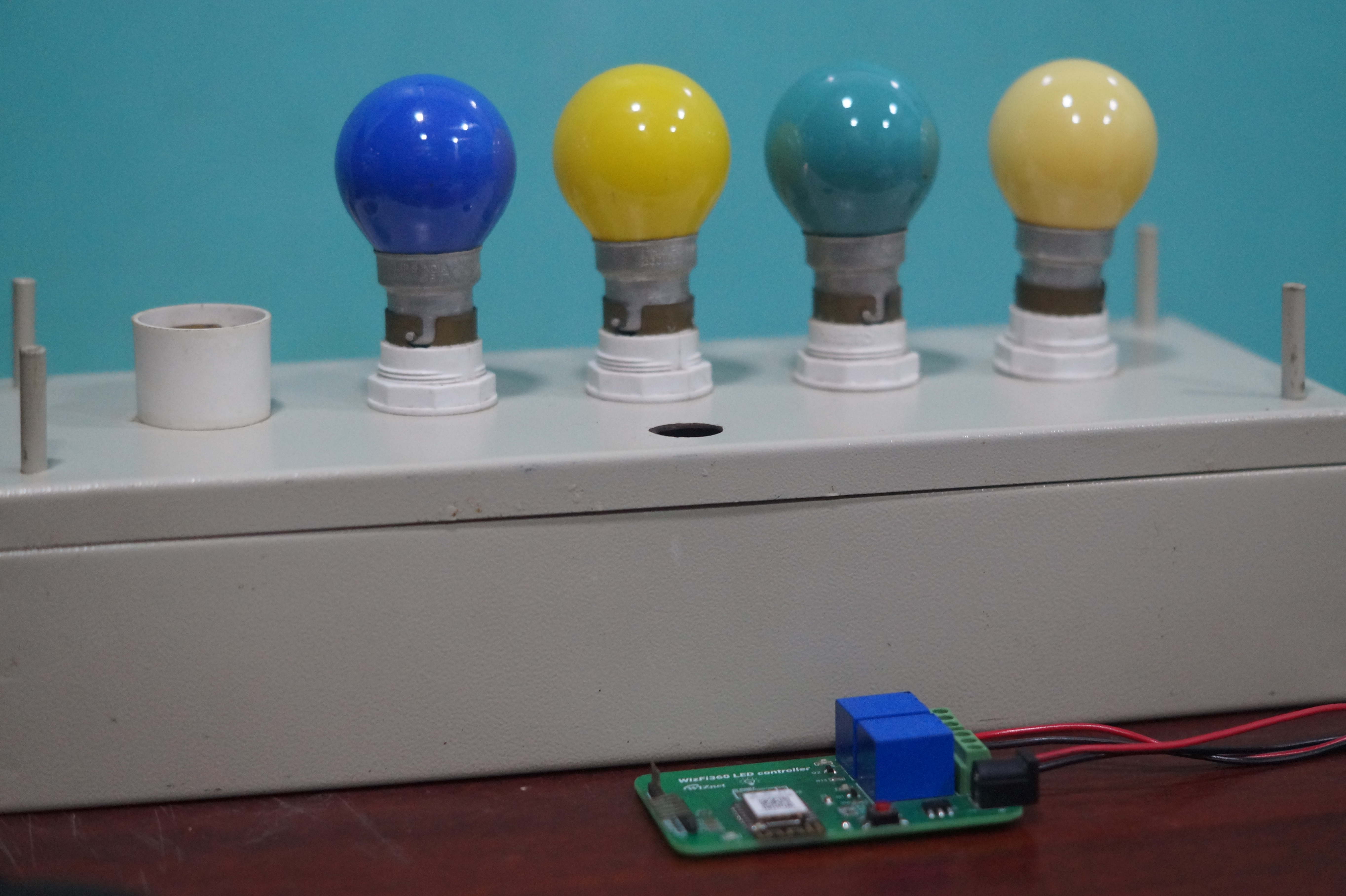

Demo video
Thanks wiznet for the free hardware and all the best to all the participants.
-
Schematics

-
AT commands