
W55MH32 Environmental Monitoring: Real-time Visualization via Built-in Web Page
W55MH32 Environmental Monitoring: Real-time Visualization via Built-in Web Page
1. Introduction
HTTP (Hypertext Transfer Protocol) is an application-layer protocol for distributed, collaborative, hypermedia information systems. Based on the TCP/IP communication protocol, it transmits data and forms the foundation of data communication on the World Wide Web (WWW). HTTP was initially designed to provide a method for publishing and receiving HTML pages. Resources requested via HTTP or HTTPS are identified by Uniform Resource Identifiers (URIs). This is a brief introduction to the HTTP protocol. For a more in-depth understanding of this protocol, please refer to the introduction on the Mozilla website: HTTP Overview - HTTP | MDN
The W55MH32 is WIZnet's newly launched high-performance Ethernet microcontroller. It utilizes a high-performance Arm® Cortex-M3 core with a maximum clock speed of 216MHz, and features 1024KB of FLASH and 96KB of SRAM. Notably, it incorporates the WIZnet TCP/IP offload engine (TOE), integrating a full hardware TCP/IP protocol stack, MAC, and PHY. It also includes a 32KB independent Ethernet transceiver buffer for eight hardware sockets, making it a true all-in-one solution.
2. Project Environment
2.1 Hardware Preparation
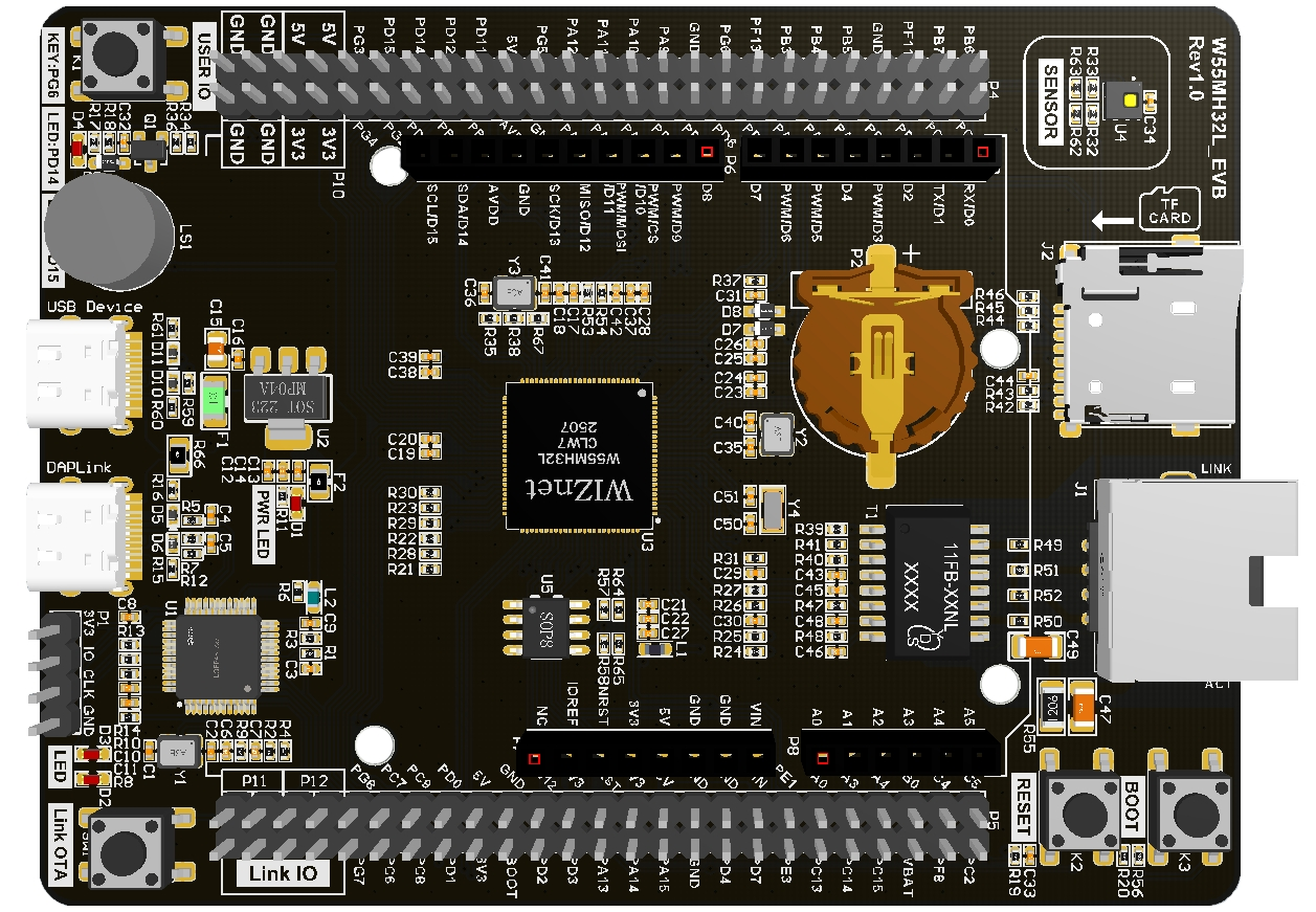
- W55MH32L-EVB
- One network cable
- USB Type-C
- C02 sensor
- Light sensor
2.2 Software Preparation
- Example link: w5500.com/w55mh32.html
- Development environment: Keil uVision 5
- Freescale Serial Port Assistant
- Browser
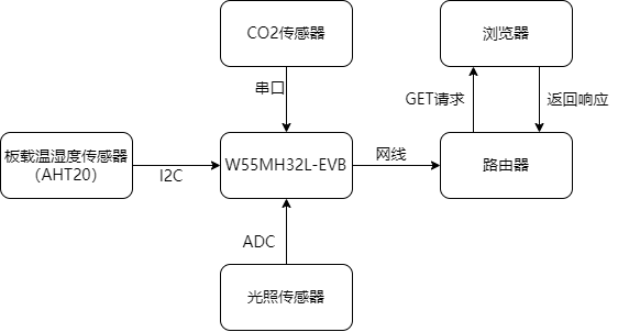
2.3 Solution Diagram
3. Application Scenarios
This project utilizes the W55MH32 to build a multi-parameter environmental monitoring system. Leveraging its low cost, high integration, and web visualization capabilities, it can be widely applied in various practical scenarios to meet the environmental sensing needs of different fields. The main application scenarios are described below:
3.1 Agricultural Greenhouse Environmental Management
In agricultural production, environmental parameters directly affect crop growth efficiency. This system can be deployed in greenhouses to:
- Real-time monitoring of temperature and humidity (affecting crop transpiration and disease risk), light intensity (a key factor in photosynthesis), and CO₂ concentration (a carbon source for crop growth);
- Remotely view data via a web page, eliminating the need for on-site inspections and reducing labor costs;
- Analyze environmental change patterns using historical data curves to optimize agricultural operations such as irrigation, ventilation, and supplemental lighting.
Compared to traditional agricultural monitoring equipment, this solution is lower in cost and supports multi-parameter integration, making it suitable for small and medium-sized growers.
3.2 Warehouse Environment Monitoring
For storage scenarios involving grains, pharmaceuticals, and electronic components, ambient temperature, humidity, and air quality are crucial for ensuring storage quality:
- Monitoring temperature and humidity within the warehouse prevents grain mold, pharmaceutical deterioration, or moisture damage to electronic components;
- Real-time tracking of CO₂ concentration in enclosed spaces prevents spoilage due to insufficient ventilation;
- Analyzing environmental trends using historical data curves optimizes storage conditions and ventilation cycles.
The system supports 24/7 operation with high data stability, making it suitable for long-term unattended storage scenarios.
3.3 Office and Public Space Monitoring
In densely populated areas such as office buildings, classrooms, and shopping malls, air quality and comfort directly impact employee health and work efficiency:
- Real-time monitoring of CO₂ concentration automatically activates the ventilation system to improve air quality when high population density leads to increased concentration;
- Light intensity data can be used for adjusting lighting in public areas, achieving energy conservation and consumption reduction;
- Management personnel can remotely view the environmental status of each area via a browser and centrally manage multiple monitoring points (multiple devices can be deployed via extended IP addresses).
The system is simple to deploy; it only requires a network cable connection to access the local area network, requiring no complex configuration.
4. Example Modification
4.1 Main Function Analysis
This code implements an environmental sensor monitoring system. It collects data on temperature, humidity, light intensity, and CO2 concentration through multiple sensors and updates the generated data curves on a webpage via HTTP.
#include <stdlib.h>
#include <string.h>
#include <stdio.h>
#include "wizchip_conf.h"
#include "wiz_interface.h"
#include "bsp_tim.h"
#include "bsp_uart.h"
#include "bsp_rcc.h"
#include "delay.h"
#include "loopback.h"
#include "bsp_adc.h"
#include "i2c_sensor.h"
#include "uart_sensor.h"
#include "light_sensor.h"

extern MYI2C_Struct SENx;

#define DEFAULT_MAC_EN        1
#define SOCKET_ID             0
#define ETHERNET_BUF_MAX_SIZE (1024 * 2)

float g_humidity_value = 0.0;
float g_temperature = 0.0;
float g_light_intensity = 0.0;
uint16_t g_co2_concentration = 0;

wiz_NetInfo default_net_info = {
   .mac  = {0x00, 0x08, 0xdc, 0x12, 0x22, 0x12},
   .ip   = {192, 168, 1, 30},
   .gw   = {192, 168, 1, 1},
   .sn   = {255, 255, 255, 0},
   .dns  = {8, 8, 8, 8},
   .dhcp = NETINFO_DHCP
};

uint16_t local_port = 8080;
uint8_t  ethernet_buf[ETHERNET_BUF_MAX_SIZE] = {0};

void read_sensors(void)
{
   g_light_intensity =light_read_intensity();

   // 读取温湿度
   MYI2C_Handle(&SENx);
   g_humidity_value = SENx.RH;
   g_temperature = SENx.T;

   // 读取CO2浓度
   g_co2_concentration = co2_sensor_get_concentration();

printf("Sensor Data - Temp: %.1fC, Humidity: %.1f%%, Light: %.0flux, CO2: %dppm\r\n",
          g_temperature, g_humidity_value, g_light_intensity, g_co2_concentration);
}
int main(void)
{
   rcc_clk_config();
   delay_init();
   console_usart_init(115200);
   tim3_init();

   printf("Environmental Sensor Monitoring System\r\n");

   adc_dma_init();
   co2_sensor_init();
   MYI2C_Init(&SENx, 2000, 0x38);

   wiz_toe_init();
#if DEFAULT_MAC_EN == 1
   getSHAR(default_net_info.mac);
#endif

   wiz_phy_link_check();
   network_init(ethernet_buf, &default_net_info);

   while (1)
   {
       read_sensors();
       loopback_tcps(SOCKET_ID, ethernet_buf, local_port);
       delay_ms(2000);
   }
}
4.2 ADC Acquisition
By configuring the ADC to continuous scanning mode and the DMA to cyclic transfer mode and linking the two, efficient continuous acquisition of data from the optical sensor connected to the PA3 pin is achieved. It also provides filtering by averaging the samples in the DMA buffer to provide raw data for light intensity calculation.
#include "bsp_adc.h"
#include "w55mh32_adc.h"
#include "w55mh32_dma.h"
#include "w55mh32_gpio.h"
#include "w55mh32_rcc.h"

/* Static buffer for ADC DMA data (stores light sensor readings) */
static uint16_t s_adc_dma_buffer[ADC_BUFFER_SIZE];

/**
* @brief Initialize ADC with DMA
* @details Configures ADC for light sensor (PA3), GPIO, and DMA for
* continuous sampling
*/
void adc_dma_init(void)
{
   ADC_InitTypeDef  adc_init_struct;
   GPIO_InitTypeDef gpio_init_struct;
   DMA_InitTypeDef  dma_init_struct;

   // Enable clocks for ADC, GPIO, and DMA
   RCC_APB2PeriphClockCmd(RCC_APB2Periph_GPIOA | RCC_APB2Periph_ADC1, ENABLE);
   RCC_AHBPeriphClockCmd(RCC_AHBPeriph_DMA1, ENABLE);

   // Configure GPIO pin PA3 as analog input (light sensor)
   gpio_init_struct.GPIO_Pin  = GPIO_Pin_3;
   gpio_init_struct.GPIO_Mode = GPIO_Mode_AIN;
   GPIO_Init(GPIOA, &gpio_init_struct);

   // Configure ADC in continuous scan mode
   ADC_StructInit(&adc_init_struct);
   adc_init_struct.ADC_Mode               = ADC_Mode_Independent;
   adc_init_struct.ADC_ScanConvMode       = ENABLE;
   adc_init_struct.ADC_ContinuousConvMode = ENABLE;
   adc_init_struct.ADC_ExternalTrigConv   = ADC_ExternalTrigConv_None;
   adc_init_struct.ADC_DataAlign          = ADC_DataAlign_Right;
   adc_init_struct.ADC_NbrOfChannel       = 1; // Only light sensor channel
   ADC_Init(ADC1, &adc_init_struct);

   // Configure ADC channel and sampling time (light sensor on PA3)
   ADC_RegularChannelConfig(ADC1, ADC_Channel_3, 1, ADC_SampleTime_55Cycles5);

   // Configure DMA for ADC data transfer
   DMA_DeInit(DMA1_Channel1);
   dma_init_struct.DMA_PeripheralBaseAddr = (uint32_t)&ADC1->DR;
   dma_init_struct.DMA_MemoryBaseAddr     = (uint32_t)s_adc_dma_buffer;
   dma_init_struct.DMA_DIR                = DMA_DIR_PeripheralSRC;
   dma_init_struct.DMA_BufferSize         = ADC_BUFFER_SIZE;
   dma_init_struct.DMA_PeripheralInc      = DMA_PeripheralInc_Disable;
   dma_init_struct.DMA_MemoryInc          = DMA_MemoryInc_Enable;
   dma_init_struct.DMA_PeripheralDataSize = DMA_PeripheralDataSize_HalfWord;
   dma_init_struct.DMA_MemoryDataSize     = DMA_MemoryDataSize_HalfWord;
   dma_init_struct.DMA_Mode               = DMA_Mode_Circular;
   dma_init_struct.DMA_Priority           = DMA_Priority_High;
   dma_init_struct.DMA_M2M                = DMA_M2M_Disable;
   DMA_Init(DMA1_Channel1, &dma_init_struct);

   // Enable DMA and ADC
   DMA_Cmd(DMA1_Channel1, ENABLE);
   ADC_DMACmd(ADC1, ENABLE);

   // Calibrate and start ADC
   ADC_Cmd(ADC1, ENABLE);
   ADC_ResetCalibration(ADC1);
   while (ADC_GetResetCalibrationStatus(ADC1));
   ADC_StartCalibration(ADC1);
   while (ADC_GetCalibrationStatus(ADC1));

   ADC_SoftwareStartConvCmd(ADC1, ENABLE);
}

/**
* @brief Get average ADC value for light sensor
* @param sample_count Number of samples to average
* @return Average ADC value (12-bit)
* @note channel_index parameter is now unused (kept for compatibility)
*/
uint16_t adc_get_average_value(uint8_t channel_index, uint8_t sample_count)
{
   uint32_t sum = 0;
   uint8_t valid_samples = 0;

   // Ensure we don't exceed buffer size
   if (sample_count > ADC_BUFFER_SIZE) {
       sample_count = ADC_BUFFER_SIZE;
   }
   // Sum recent light sensor readings from DMA buffer
   for (uint8_t i = 0; i < sample_count; i++) {
       sum += s_adc_dma_buffer[i];
       valid_samples++;
   }
   return (valid_samples > 0) ? (sum / valid_samples) : 0;
}
4.3 CO2 Sensor Reading
The CO₂ sensor driver function was implemented. UART communication with the sensor was established via USART3 (baud rate 9600bps, 8 data bits, 1 stop bit, no parity). This included initializing GPIO and serial port hardware, and configuring interrupt priorities to handle received data. The code uses the `co2_sensor_byte_handle` function to receive data byte by byte, assembling data frames according to a fixed format (6-byte frame, first byte 0x2C). The `co2_sensor_process_data_frame` function then verifies the checksum (B6 is the 8-bit sum of B1-B5). If the checksum passes, bytes B2 and B3 are combined to calculate the CO₂ concentration (in PPM) and stored in a global variable. Finally, the `co2_sensor_get_concentration` function provides the data for external retrieval. Overall, reliable reception, verification, and parsing of sensor data were achieved.
/**
* @file co2_sensor.c
* @brief CO₂ Sensor drive
*
* @section uart_config UART Configuration
* | Parameter    | Value       | Description                  |
* |--------------|-------------|------------------------------|
* | Baud Rate    | 9600bps     | Data transmission rate       |
* | Data Bits    | 8 bits      | Number of data bits per frame|
* | Stop Bit     | 1 bit       | Stop bit count               |
* | Parity       | None        | No parity check              |
*
* @section data_format Data Frame Format
* A complete UART data frame consists of 6 bytes (B1 - B6), structured as:
*
* | Byte Index | Field Name        | Fixed Value/Description       |
* |------------|-------------------|-------------------------------|
* | B1         | Module Address    | 0x2C (fixed module address)   |
* | B2         | CO₂ High Byte     | 0XXh (high 8 bits of CO₂ data)|
* | B3         | CO₂ Low Byte      | 0XXh (low 8 bits of CO₂ data) |
* | B4         | Full Scale High   | 0x03h (fixed value)           |
* | B5         | Full Scale Low    | 0xFFh (fixed value)           |
* | B6         | Checksum          | unit_8 sum of B1-B5           |
*
* @section checksum_calc Checksum Calculation
* Checksum (B6) is computed as:
* \f$ B6 = \text{unit\_8}(B1 + B2 + B3 + B4 + B5) \f$
* (Sum B1-B5, then take the 8-bit result)
*
* @section co2_calc CO₂ Concentration Calculation
* CO₂ concentration (in PPM) is calculated by:
* \f$ \text{CO₂ (PPM)} = (B2 \times 256) + B3 \f$
* (Combine high/low bytes of CO₂ data into a 16-bit value)
*
* @section example Example Data
* Sample received data frame: 0x2C, 0x01h, 0x90h, 0x03h, 0xFFh, 0xBFh
* - Checksum Validation:
*   \f$ 0xBFh = 0x2C + 0x01h + 0x90h + 0x03h + 0xFFh \f$ (valid)
* - CO₂ Concentration:
*   \f$ (0x01h \times 256) + 0x90h = 256 + 144 = 400 \text{ PPM} \f$
*
* @note Ensure data frame length (6 bytes) and module address (B1=0x2C)
*       are validated before processing.
*
*/
#include "w55mh32.h"

static uint16_t g_co2_concentration = 0; /* Global variable to store current CO2 concentration value */

/**
* @brief Initialize CO2 sensor
* @details Configure USART3 and related GPIO pins, set baud rate to 9600,
*          8 data bits, 1 stop bit, no parity
*/
void co2_sensor_init(void)
{
   GPIO_InitTypeDef  GPIO_InitStructure;
   USART_InitTypeDef USART_InitStructure;
   NVIC_InitTypeDef  NVIC_InitStructure;

   /* Enable GPIOB and USART3 clock */
   RCC_APB2PeriphClockCmd(RCC_APB2Periph_GPIOB, ENABLE);
   RCC_APB1PeriphClockCmd(RCC_APB1Periph_USART3, ENABLE);

   /* Configure USART3 TX pin (PB10) as alternate function push-pull */
   GPIO_InitStructure.GPIO_Pin   = GPIO_Pin_10;
   GPIO_InitStructure.GPIO_Speed = GPIO_Speed_50MHz;
   GPIO_InitStructure.GPIO_Mode  = GPIO_Mode_AF_PP;
   GPIO_Init(GPIOB, &GPIO_InitStructure);

   /* Configure USART3 RX pin (PB11) as input floating */
   GPIO_InitStructure.GPIO_Pin  = GPIO_Pin_11;
   GPIO_InitStructure.GPIO_Mode = GPIO_Mode_IN_FLOATING;
   GPIO_Init(GPIOB, &GPIO_InitStructure);

   /* Configure USART3 parameters */
   USART_InitStructure.USART_BaudRate            = 9600;
   USART_InitStructure.USART_WordLength          = USART_WordLength_8b;
   USART_InitStructure.USART_StopBits            = USART_StopBits_1;
   USART_InitStructure.USART_Parity              = USART_Parity_No;
   USART_InitStructure.USART_HardwareFlowControl = USART_HardwareFlowControl_None;
   USART_InitStructure.USART_Mode                = USART_Mode_Rx | USART_Mode_Tx;
   USART_Init(USART3, &USART_InitStructure);
   USART_ITConfig(USART3, USART_IT_RXNE, ENABLE);

   /* Configure USART3 interrupt priority */
   NVIC_InitStructure.NVIC_IRQChannel                   = USART3_IRQn;
   NVIC_InitStructure.NVIC_IRQChannelPreemptionPriority = 0;
   NVIC_InitStructure.NVIC_IRQChannelSubPriority        = 2;
   NVIC_InitStructure.NVIC_IRQChannelCmd                = ENABLE;
   NVIC_Init(&NVIC_InitStructure);

   /* Enable USART3 */
   USART_Cmd(USART3, ENABLE);
}

/**
* @brief Get current CO2 concentration
* @return Current CO2 concentration in PPM
*/
uint16_t co2_sensor_get_concentration(void)
{
   return g_co2_concentration;
}

/**
* @brief Process received data frame from CO2 sensor
* @param frame Pointer to the 6-byte data frame
* @details Validates checksum and updates CO2 concentration if checksum is correct
*/
static void co2_sensor_process_data_frame(uint8_t *frame)
{
   uint8_t i;
   uint8_t checksum = 0;

   /* Calculate checksum */
   for (i = 0; i < 5; i++)
   {
       checksum += frame[i];
   }

   /* Update CO2 concentration if checksum matches */
   if (checksum == frame[5])
   {
       g_co2_concentration = frame[1] * 256 + frame[2];
   }
}

/**
* @brief Handle received byte from CO2 sensor
* @param data Received byte
* @details Assembles complete data frame and processes it when full frame is received
*/
void co2_sensor_byte_handle(uint8_t data)
{
   static uint8_t co2_data_frame[6];
   static uint8_t co2_data_index = 0;

   /* Check for frame start (0x2C) */
   if (co2_data_index == 0 && data == 0x2C)
   {
       co2_data_frame[co2_data_index++] = data;
   }
   /* Continue collecting frame data */
   else if (co2_data_index < 6)
   {
       co2_data_frame[co2_data_index++] = data;
       /* Process complete frame */
       if (co2_data_index == 6)
       {
           co2_sensor_process_data_frame(co2_data_frame);
           co2_data_index = 0;
       }
   }
   else
   {
       co2_data_index = 0;
   }
}

/**
* @brief USART3 interrupt handler
* @details Processes received data and clears interrupt flag
*/
void USART3_IRQHandler(void)
{
   uint8_t data;
   if (USART_GetITStatus(USART3, USART_IT_RXNE) != RESET)
   {
       /* Read received data and process it */
       data = (uint8_t)USART_ReceiveData(USART3);
       co2_sensor_byte_handle(data);

       /* Clear interrupt flag */
       USART_ClearITPendingBit(USART3, USART_IT_RXNE);
   }
}
4.4 Temperature and Humidity Sensor Reading
This file implements the driver functions for the I2C communication protocol, including initializing I2C-related GPIO pins (configuring them as open-drain output or input modes), defining I2C start/stop signals, acknowledge/wait-for-acknowledge, and basic communication functions such as byte read/write. It also provides functions for reading and writing device registers via I2C and implements CRC8 verification to ensure data transmission correctness. The code also includes processing logic for the temperature and humidity sensor, managing the sensor workflow through a state machine (idle, measurement, completion). During the measurement phase, it sends commands and reads 7 bytes of data. After verification, it parses and calculates the humidity (RH) and temperature (T) values. Finally, the MYI2C_Handle function completes the entire sensor data acquisition and processing process for reading the AHT20 temperature and humidity sensor on the W55MH32L-EVB board.
#include "i2c_sensor.h "
#include "delay.h"

MYI2C_Struct SENx;


/**********************************************
//MYI2C_Delay_us
**********************************************/
void MYI2C_Delay_us(unsigned long nTim)
{
   unsigned int i;

   while (nTim--)
   {
       i = MYI2C_delay_us_cnt;
       while (i--);
   }
}
/*******************************************************************************
* Function Name  : MYI2C_GPIO_MODE
* Description    : Configures the different GPIO ports.
* Input          : None
* Output         : None
* Return         : None
*******************************************************************************/
void MYI2C_GPIO_MODE(unsigned char TYP) //根据MCU修改相应的IO初始化
{
#ifdef ARM32
   GPIO_InitTypeDef GPIO_InitStruct;
#endif
   switch (TYP)
   {
   case SDA_OUT: //设置开漏输出,需要加外部上拉电阻
#ifdef ARM32
       GPIO_InitStruct.GPIO_Mode  = GPIO_Mode_Out_OD;
       GPIO_InitStruct.GPIO_Pin   = SDA_Pin;
       GPIO_InitStruct.GPIO_Speed = GPIO_Speed_50MHz;
       GPIO_Init(IIC_SDA_PORT, &GPIO_InitStruct);
#else
       P0M0 |= 1 << 3;
       P0M1 |= 3 << 2;
#endif
       break;
   case SDA_IN: //设置输入,需要加外部上拉电阻
#ifdef ARM32
       GPIO_InitStruct.GPIO_Mode  = GPIO_Mode_IPU;
       GPIO_InitStruct.GPIO_Pin   = SDA_Pin;
       GPIO_InitStruct.GPIO_Speed = GPIO_Speed_50MHz;
       GPIO_Init(IIC_SDA_PORT, &GPIO_InitStruct);
#else
       P0M0 &= ~(1 << 3);
       P0M1 |= 3 << 2;
#endif
       break;
   case SCL_OUT: //设置开漏输出,需要加外部上拉电阻
#ifdef ARM32
       GPIO_InitStruct.GPIO_Mode  = GPIO_Mode_Out_OD;
       GPIO_InitStruct.GPIO_Pin   = SCL_Pin;
       GPIO_InitStruct.GPIO_Speed = GPIO_Speed_50MHz;
       GPIO_Init(IIC_SCL_PORT, &GPIO_InitStruct);
#else
       P0M0 |= 1 << 2;
       P0M1 |= 3 << 2;
#endif
       break;
   }
}
/*******************************************************************************
* Function Name  : MYI2C_GPIO_DATA
* Description    : Configures the different GPIO ports.
* Input          : None
* Output         : None
* Return         : None
*******************************************************************************/
unsigned char MYI2C_GPIO_DATA(unsigned char TYP) //根据MCU修改相应的IO操作
{
   unsigned int dat = 0;

   switch (TYP)
   {
   case SDA_H:
#ifdef ARM32
       GPIO_SetBits(IIC_SDA_PORT, SDA_Pin);
#else
       I2C_SDA_PIN = 1;
#endif
       break;
   case SDA_L:
#ifdef ARM32
       GPIO_ResetBits(IIC_SDA_PORT, SDA_Pin);
#else
       I2C_SDA_PIN = 0;
#endif
       break;
   case SCL_H:
#ifdef ARM32
       GPIO_SetBits(IIC_SCL_PORT, SCL_Pin);
#else
       I2C_SCL_PIN = 1;
#endif
       break;
   case SCL_L:
#ifdef ARM32
       GPIO_ResetBits(IIC_SCL_PORT, SCL_Pin);
#else
       I2C_SCL_PIN = 0;
#endif
       break;
   case SDA_R:
#ifdef ARM32
       dat = GPIO_ReadInputDataBit(IIC_SDA_PORT, SDA_Pin);
#else
       dat = I2C_SDA_PIN;
#endif
       break;
   }

   return dat;
}
/**********************************************
//IIC Start
**********************************************/
void MYI2C_IIC_Start(void)
{
   MYI2C_SCK_Set();
   MYI2C_SDA_Set();
   MYI2C_SDA_Clr();
   MYI2C_SCK_Clr();
}
/**********************************************
//IIC Stop
**********************************************/
void MYI2C_IIC_Stop(void)
{
   MYI2C_SCK_Clr();
   MYI2C_SDA_Clr();
   MYI2C_SCK_Set();
   MYI2C_SDA_Set();
}
/**********************************************
//IIC Ack
**********************************************/
void MYI2C_IIC_Ack(unsigned char ack)
{
   MYI2C_SCK_Clr();
   if (ack)
   {
       MYI2C_SDA_Clr();
   }
   else
   {
       MYI2C_SDA_Set();
   }
   MYI2C_SCK_Set();
}
/**********************************************
//IIC Wait_Ack
**********************************************/
unsigned char MYI2C_IIC_Wait_Ack(unsigned int wait_time)
{
   MYI2C_SCK_Clr();
   MYI2C_SDA_IN_Mode;
   MYI2C_SDA_Set();
   MYI2C_SCK_Set();
   while (wait_time)
   {
       if (MYI2C_GPIO_DATA(SDA_R) == 0) break;
       MYI2C_Delay_us(1);
       wait_time--; //=======================
   }

   MYI2C_SDA_OD_Mode;
   return wait_time; //是否应答=======================
}
/**********************************************
// IIC Write byte
**********************************************/
void MYI2C_Write_IIC_Byte(unsigned char dat)
{
   unsigned char i;

   for (i = 0; i < 8; i++)
   {
       MYI2C_SCK_Clr();
       if (dat & 0x80)
       {
           MYI2C_SDA_Set();
       }
       else
       {
           MYI2C_SDA_Clr();
       }
       MYI2C_SCK_Set();
       dat = dat << 1;
   }
}
/**********************************************
// IIC Read byte
**********************************************/
unsigned char MYI2C_Read_IIC_Byte(void)
{
   unsigned char i, byt = 0;

   MYI2C_SCK_Clr();
   MYI2C_SDA_IN_Mode;
   MYI2C_SDA_Set();
   for (i = 0; i < 8; i++)
   {
       MYI2C_SCK_Clr();
       if (MYI2C_GPIO_DATA(SDA_R)) byt++;
       MYI2C_SCK_Set();
       if (i < 7) byt = byt << 1;
   }
   MYI2C_SDA_OD_Mode;

   return byt;
}

/*******************************************************************************
* Function Name  : MYI2C_Init
* Description    : 初始化MYI2C
* Input          :  None
* Output         : None
* Return         :None
*******************************************************************************/
void MYI2C_Init(MYI2C_Struct *pst, unsigned int ReadTimMS, unsigned char xAddr)
{
   RCC_APB2PeriphClockCmd(RCC_APB2Periph_GPIOB, ENABLE); //使能SDA、SCL端口时钟,如是51单片机不需要则注释掉该行。

   pst->Adrr = xAddr;
   pst->Step = SENSOR_IDLE;
   if (ReadTimMS > MinReadTim)
       pst->SetRTim = ReadTimMS;
   else
       pst->SetRTim = MinReadTim;

   MYI2C_SCK_OD_Mode;
   MYI2C_SDA_OD_Mode;

   MYI2C_SCK_Set();
   MYI2C_SDA_Set();
}
/*******************************************************************************
* Function Name  :
* Description    :
* Input          :None
* Output         :None
* Return         :None
*******************************************************************************/
unsigned char MYI2C_READ_FUNC(MYI2C_Struct *pst, unsigned char device_addr, unsigned char register_addr, unsigned char *pDat, unsigned char len)
{
   unsigned char NoAck = 0;

   if (register_addr)
   {
       /* Send STRAT condition a second time */
       MYI2C_IIC_Start();
       /* Send slave address for Write Regsiter */
       MYI2C_Write_IIC_Byte((device_addr << 1) + 0);
       /* Ack */
       if (MYI2C_IIC_Wait_Ack(Wait_Ack_time) == 0) NoAck++;
       /*Send register_addr*/
       MYI2C_Write_IIC_Byte((register_addr));
       /* Ack */
       if (MYI2C_IIC_Wait_Ack(Wait_Ack_time) == 0) NoAck++;

       //   MYI2C_IIC_Stop(pst);
       MYI2C_SCK_Clr();
       MYI2C_SCK_Set();
   }
   /* Send STRAT condition a second time */
   MYI2C_IIC_Start();
   /* Send slave address for Read */
   MYI2C_Write_IIC_Byte((device_addr << 1) + 1);
   /* Ack */
   if (MYI2C_IIC_Wait_Ack(Wait_Ack_time) == 0) NoAck++;
   /* While there is data to be read */
   while (len && NoAck == 0 && len < MYI2C_Buffer_Size) //
   {
       *pDat = MYI2C_Read_IIC_Byte();
       /*  Ack */
       MYI2C_IIC_Ack(len - 1); //len = 1 NoAck
       pDat++;
       len--;
   }
   /* Send STOP Condition */
   MYI2C_IIC_Stop();

   pst->ErrFlag = NoAck;

   return NoAck;
}
/*******************************************************************************
* Function Name  :
* Description    :
* Input          :  None
* Output         : None
* Return         :None
*******************************************************************************/
unsigned char MYI2C_WRITE_FUNC(MYI2C_Struct *pst, unsigned char device_addr, unsigned char register_addr, unsigned char *pDat, unsigned char len)
{
   unsigned int NoAck = 0;

   /* Send STRAT condition */
   MYI2C_IIC_Start();
   /* Send slave address for write */
   MYI2C_Write_IIC_Byte((device_addr << 1) + 0);
   /* ACK */
   if (MYI2C_IIC_Wait_Ack(Wait_Ack_time) == 0) NoAck++;
   /* Send register_addr for read */
   MYI2C_Write_IIC_Byte((register_addr));
   /* ACK */
   if (MYI2C_IIC_Wait_Ack(Wait_Ack_time) == 0) NoAck++;
   while (NoAck == 0 && len && len < MYI2C_Buffer_Size) //
   {
       /* Send the byte to be written */
       MYI2C_Write_IIC_Byte(*pDat);
       /*  Acknowledgement */
       MYI2C_IIC_Wait_Ack(Wait_Ack_time);
       pDat++;
       len--;
   }
   /* Send STOP condition */
   MYI2C_IIC_Stop();

   pst->ErrFlag = NoAck;

   return NoAck;
}
/*******************************************************************************
* Function Name  : CheckCrc
* Description    :
* Input          :  None
* Output         : None
* Return         :None
*******************************************************************************/
unsigned char CheckCrc8(unsigned char *pDat, unsigned char Lenth)
{
   unsigned char crc = 0xff, i, j;

   for (i = 0; i < Lenth; i++)
   {
       crc = crc ^ *pDat;
       for (j = 0; j < 8; j++)
       {
           if (crc & 0x80)
               crc = (crc << 1) ^ 0x31;
           else
               crc <<= 1;
       }
       pDat++;
   }
   return crc;
}
/*******************************************************************************
* Function Name  :
* Description    :
* Input          :None
* Output         :None
* Return         :None
*******************************************************************************/
void MYI2C_Handle(MYI2C_Struct *pst)
{
   unsigned long s32x;

   pst->timcnt += MYI2C_Tick;
   if (pst->timcnt > PowerOnTim && pst->Step == SENSOR_IDLE)
   {
       pst->Step        = SENSOR_MEASURE;
       pst->SendByte[0] = 0x33;
       pst->SendByte[1] = 0x00;
       MYI2C_WRITE_FUNC(pst, pst->Adrr, 0xAC, &pst->SendByte[0], 2);
   }
   else if (pst->timcnt > MeasureTim && pst->Step == SENSOR_MEASURE)
   {
       pst->Step = SENSOR_COMPLETE;
       MYI2C_READ_FUNC(pst, pst->Adrr, 0, &pst->ReadByte[0], 7);
       if (pst->ErrFlag == 0)
       {
           if ((CheckCrc8(&pst->ReadByte[0], 6) == pst->ReadByte[6]) && ((pst->ReadByte[0] & 0x98) == 0x18))
           {
               s32x     = pst->ReadByte[1];
               s32x     = s32x << 8;
               s32x    += pst->ReadByte[2];
               s32x     = s32x << 8;
               s32x    += pst->ReadByte[3];
               s32x     = s32x >> 4;
               pst->RH  = s32x;
               pst->RH  = pst->RH * 100 / 1048576;
               s32x     = pst->ReadByte[3] & 0x0F;
               s32x     = s32x << 8;
               s32x    += pst->ReadByte[4];
               s32x     = s32x << 8;
               s32x    += pst->ReadByte[5];
               pst->T   = s32x;
               pst->T   = pst->T * 200 / 1048576 - 50;
           }
       }
       else
       {
           pst->RH = 0;
           pst->T  = 0;
       }
   }
   else if (pst->timcnt > pst->SetRTim)
   {
       pst->Step   = SENSOR_IDLE;
       pst->timcnt = 0;
   }
}
4.5 Web Communication Processing
This code implements a TCP-based HTTP server function. It manages Socket connections through a state machine (including initialization, listening, connection establishment, and closing states), parses HTTP request lines to obtain method, URI, and version information, and responds to different requests: returning a 204 "No Content" error for OPTIONS requests, sending web page content for root path GET requests, returning sensor data such as temperature, humidity, light intensity, and CO₂ concentration in JSON format for `/api/sensor` path GET requests, and returning a 400 or 404 error for invalid requests. It also handles data transmission and connection disconnection logic, enabling network access to sensor data.
#include "loopback.h"
#include "socket.h"
#include "web_page.h"
#include "wizchip_conf.h"
#include <stdio.h>
#include <stdlib.h>
#include <string.h>

#define DATA_BUF_SIZE 1024

extern float g_humidity_value;
extern float g_temperature;
extern float g_light_intensity;
extern uint16_t g_co2_concentration;

typedef struct {
   char method[16];
   char uri[256];
   char version[16];
} HttpReqLine;

static int http_parse_request_line(const char *request, HttpReqLine *req_line)
{
   char buffer[1024];
   strncpy(buffer, request, sizeof(buffer));
   buffer[sizeof(buffer) - 1] = '\0';

   char *line_end = strstr(buffer, "\r\n");
   if (!line_end) line_end = strstr(buffer, "\n");
   if (!line_end) return -1;
   *line_end = '\0';

   char *method = strtok(buffer, " ");
   char *uri = strtok(NULL, " ");
   char *version = strtok(NULL, " ");

   if (!method || !uri || !version) return -1;

   strncpy(req_line->method, method, sizeof(req_line->method) - 1);
   strncpy(req_line->uri, uri, sizeof(req_line->uri) - 1);
   strncpy(req_line->version, version, sizeof(req_line->version) - 1);

   return 0;
}

static void send_http_response(uint8_t sn, const char *status,
                              const char *content_type, const char *body)
{
   char response[512];
   int body_len = strlen(body);

   sprintf(response,
           "HTTP/1.1 %s\r\n"
           "Content-Type: %s\r\n"
           "Access-Control-Allow-Origin: *\r\n"
           "Connection: close\r\n"
           "Content-Length: %d\r\n"
           "\r\n"
           "%s",
           status, content_type, body_len, body);

   send(sn, (uint8_t *)response, strlen(response));
}

int32_t loopback_tcps(uint8_t sn, uint8_t *network_buf, uint16_t port)
{
   int32_t ret;
   uint16_t recv_size = 0;
   uint16_t send_size = 0;

   switch (getSn_SR(sn)) {
       case SOCK_ESTABLISHED:
           if (getSn_IR(sn) & Sn_IR_CON) {
               setSn_IR(sn, Sn_IR_CON);
           }

           if ((recv_size = getSn_RX_RSR(sn)) > 0) {
               if (recv_size > DATA_BUF_SIZE) recv_size = DATA_BUF_SIZE;

               ret = recv(sn, network_buf, recv_size);
               if (ret <= 0) return ret;

               recv_size = (uint16_t)ret;
               network_buf[recv_size] = '\0';

               HttpReqLine req_line;
               if (http_parse_request_line((char *)network_buf, &req_line) == 0) {
                   printf("HTTP %s: %s\n", req_line.method, req_line.uri);

                   if (strcmp(req_line.method, "OPTIONS") == 0) {
                       send_http_response(sn, "204 No Content", "text/plain", "");
                   }
                   else if (strcmp(req_line.method, "GET") == 0 && strcmp(req_line.uri, "/") == 0) {
                       // 直接发送 index_page
                       uint16_t content_len = strlen(index_page);
                       send_size = 0;
                       while (send_size < content_len) {
                           ret = send(sn, (uint8_t *)index_page + send_size, content_len - send_size);
                           if (ret < 0) {
                               close(sn);
                               return ret;
                           }
                           send_size += ret;
                       }
                   }
                   else if (strcmp(req_line.method, "GET") == 0 && strcmp(req_line.uri, "/api/sensor") == 0) {
                       char sensor_json[256];
                       sprintf(sensor_json,
                               "{\"temp\":%.1f,\"humi\":%.1f,\"light\":%.1f,\"co2\":%d}",
                               g_temperature, g_humidity_value, g_light_intensity, g_co2_concentration);
                       send_http_response(sn, "200 OK", "application/json", sensor_json);
                   }
                   else {
                       send_http_response(sn, "404 Not Found", "text/html",
                                          "<html><body>Page Not Found</body></html>");
                   }
               }
               else {
                   send_http_response(sn, "400 Bad Request", "text/plain", "Invalid request");
               }

               disconnect(sn);
               close(sn);
           }
           break;

       case SOCK_CLOSE_WAIT:
           disconnect(sn);
           break;

       case SOCK_INIT:
           listen(sn);
           break;

       case SOCK_CLOSED:
           socket(sn, Sn_MR_TCP, port, 0x00);
           break;

       default:
           break;
   }
   return 1;
}
4.6 Webpage Display
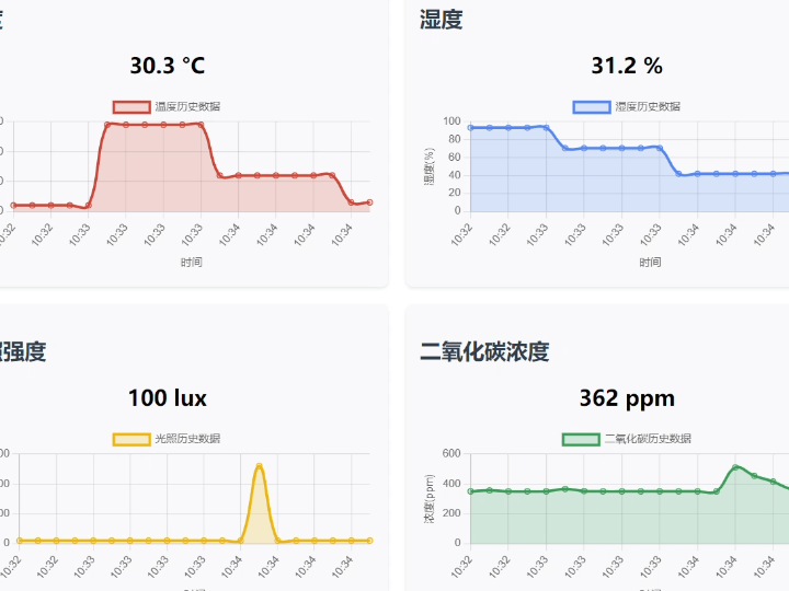
This code defines an HTML page for an environmental sensor dashboard. By importing Chart.js, it displays real-time values of temperature, humidity, light intensity, and carbon dioxide concentration, as well as historical data line charts. It supports manual refresh and automatic refresh every 5 seconds. It obtains data from the `/api/sensor` interface and dynamically updates the page content. The overall design uses a grid layout and responsive design to enhance the visual experience.
#ifndef _WEBP_PAGE_H_
#define _WEBP_PAGE_H_

#define index_page \
"HTTP/1.1 200 OK\r\n" \
"Content-Type: text/html\r\n" \
"Connection: close\r\n" \
"\r\n" \
"<!DOCTYPE html>\r\n" \
"<html>\r\n" \
"<head>\r\n" \
"    <meta charset=\"UTF-8\">\r\n" \
"    <title>传感器仪表盘</title>\r\n" \
"    <script src=\"https://cdn.jsdelivr.net/npm/chart.js\"></script>\r\n" \
"    <style>\r\n" \
"        body { font-family: \"Microsoft YaHei\", \"微软雅黑\", sans-serif; max-width: 1000px; margin: 0 auto; padding: 20px; }\r\n" \
"        .dashboard { display: grid; grid-template-columns: repeat(2, 1fr); gap: 20px; }\r\n" \
"        .sensor-panel { background: #f8f9fa; padding: 15px; border-radius: 8px; box-shadow: 0 2px 4px rgba(0,0,0,0.1); }\r\n" \
"        .chart-container { height: 200px; margin-top: 15px; }\r\n" \
"        .refresh-btn { background: #4CAF50; color: white; border: none; padding: 10px 15px; border-radius: 4px; cursor: pointer; width: 100%; margin: 10px 0; font-size: 16px; }\r\n" \
"        .value-display { font-size: 24px; font-weight: bold; text-align: center; margin: 10px 0; }\r\n" \
"        h1, h2 { color: #2c3e50; }\r\n" \
"    </style>\r\n" \
"</head>\r\n" \
"<body>\r\n" \
"    <h1 style=\"text-align: center;\">环境传感器仪表盘</h1>\r\n" \
"    <button id=\"refresh_button\" class=\"refresh-btn\">刷新数据</button>\r\n" \
"    \r\n" \
"    <div class=\"dashboard\">\r\n" \
"        <div class=\"sensor-panel\">\r\n" \
"            <h2>温度</h2>\r\n" \
"            <div id=\"temp_value\" class=\"value-display\">-- °C</div>\r\n" \
"            <div class=\"chart-container\">\r\n" \
"                <canvas id=\"temp_chart\"></canvas>\r\n" \
"            </div>\r\n" \
"        </div>\r\n" \
"        \r\n" \
"        <div class=\"sensor-panel\">\r\n" \
"            <h2>湿度</h2>\r\n" \
"            <div id=\"humi_value\" class=\"value-display\">-- %</div>\r\n" \
"            <div class=\"chart-container\">\r\n" \
"                <canvas id=\"humi_chart\"></canvas>\r\n" \
"            </div>\r\n" \
"        </div>\r\n" \
"        \r\n" \
"        <div class=\"sensor-panel\">\r\n" \
"            <h2>光照强度</h2>\r\n" \
"            <div id=\"light_value\" class=\"value-display\">-- lux</div>\r\n" \
"            <div class=\"chart-container\">\r\n" \
"                <canvas id=\"light_chart\"></canvas>\r\n" \
"            </div>\r\n" \
"        </div>\r\n" \
"        \r\n" \
"        <div class=\"sensor-panel\">\r\n" \
"            <h2>二氧化碳浓度</h2>\r\n" \
"            <div id=\"co2_value\" class=\"value-display\">-- ppm</div>\r\n" \
"            <div class=\"chart-container\">\r\n" \
"                <canvas id=\"co2_chart\"></canvas>\r\n" \
"            </div>\r\n" \
"        </div>\r\n" \
"    </div>\r\n" \
"    \r\n" \
"    <script>\r\n" \
"        // 初始化变量和DOM元素\r\n" \
"        const sensors = {\r\n" \
"            temp: { element: document.getElementById('temp_value'), chart: null, values: [] },\r\n" \
"            humi: { element: document.getElementById('humi_value'), chart: null, values: [] },\r\n" \
"            light: { element: document.getElementById('light_value'), chart: null, values: [] },\r\n" \
"            co2: { element: document.getElementById('co2_value'), chart: null, values: [] }\r\n" \
"        };\r\n" \
"        \r\n" \
"        const refreshBtn = document.getElementById('refresh_button');\r\n" \
"        const url = '/api/sensor';\r\n" \
"        \r\n" \
"        // 初始化图表\r\n" \
"        function initCharts() {\r\n" \
"            // 传感器中文名称映射\r\n" \
"            const sensorNames = {\r\n" \
"                temp: '温度',\r\n" \
"                humi: '湿度',\r\n" \
"                light: '光照',\r\n" \
"                co2: '二氧化碳'\r\n" \
"            };\r\n" \
"            \r\n" \
"            Object.keys(sensors).forEach(sensor => {\r\n" \
"                const ctx = document.getElementById(sensor + '_chart').getContext('2d');\r\n" \
"                sensors[sensor].chart = new Chart(ctx, {\r\n" \
"                    type: 'line',\r\n" \
"                    data: {\r\n" \
"                        labels: [],\r\n" \
"                        datasets: [{\r\n" \
"                            label: sensorNames[sensor] + '历史数据',\r\n" \
"                            data: [],\r\n" \
"                            borderColor: getColor(sensor),\r\n" \
"                            backgroundColor: getColor(sensor, 0.2),\r\n" \
"                            tension: 0.4,\r\n" \
"                            fill: true\r\n" \
"                        }]\r\n" \
"                    },\r\n" \
"                    options: {\r\n" \
"                        responsive: true,\r\n" \
"                        maintainAspectRatio: false,\r\n" \
"                        scales: {\r\n" \
"                            y: { \r\n" \
"                                beginAtZero: sensor !== 'temp',\r\n" \
"                                title: {\r\n" \
"                                    display: true,\r\n" \
"                                    text: sensor === 'temp' ? '温度(°C)' : \r\n" \
"                                           sensor === 'humi' ? '湿度(%)' : \r\n" \
"                                           sensor === 'light' ? '光照(lux)' : '浓度(ppm)'\r\n" \
"                                }\r\n" \
"                            },\r\n" \
"                            x: {\r\n" \
"                                title: {\r\n" \
"                                    display: true,\r\n" \
"                                    text: '时间'\r\n" \
"                                }\r\n" \
"                            }\r\n" \
"                        },\r\n" \
"                        plugins: {\r\n" \
"                            legend: {\r\n" \
"                                labels: {\r\n" \
"                                    font: {\r\n" \
"                                        family: 'Microsoft YaHei',\r\n" \
"                                        size: 12\r\n" \
"                                    }\r\n" \
"                                }\r\n" \
"                            }\r\n" \
"                        }\r\n" \
"                    }\r\n" \
"                });\r\n" \
"            });\r\n" \
"        }\r\n" \
"        \r\n" \
"        // 获取传感器对应的颜色\r\n" \
"        function getColor(sensor, opacity = 1) {\r\n" \
"            const colors = {\r\n" \
"                temp: `rgba(219, 68, 55, ${opacity})`,\r\n" \
"                humi: `rgba(66, 133, 244, ${opacity})`,\r\n" \
"                light: `rgba(244, 180, 0, ${opacity})`,\r\n" \
"                co2: `rgba(15, 157, 88, ${opacity})`\r\n" \
"            };\r\n" \
"            return colors[sensor] || `rgba(100, 100, 100, ${opacity})`;\r\n" \
"        }\r\n" \
"        \r\n" \
"        // 更新传感器显示和图表\r\n" \
"        function updateSensorData(data) {\r\n" \
"            // 更新数值显示\r\n" \
"            sensors.temp.element.textContent = data.temp.toFixed(1) + ' °C';\r\n" \
"            sensors.humi.element.textContent = data.humi.toFixed(1) + ' %';\r\n" \
"            sensors.light.element.textContent = Math.round(data.light) + ' lux';\r\n" \
"            sensors.co2.element.textContent = data.co2 + ' ppm';\r\n" \
"            \r\n" \
"            // 更新图表\r\n" \
"            const now = new Date();\r\n" \
"            const timeLabel = now.getHours() + ':' + now.getMinutes().toString().padStart(2, '0');\r\n" \
"            \r\n" \
"            Object.keys(sensors).forEach(sensor => {\r\n" \
"                const chart = sensors[sensor].chart;\r\n" \
"                const values = sensors[sensor].values;\r\n" \
"                \r\n" \
"                values.push(data[sensor]);\r\n" \
"                if (values.length > 20) values.shift();\r\n" \
"                \r\n" \
"                chart.data.labels.push(timeLabel);\r\n" \
"                if (chart.data.labels.length > 20) chart.data.labels.shift();\r\n" \
"                \r\n" \
"                chart.data.datasets[0].data = [...values];\r\n" \
"                chart.update();\r\n" \
"            });\r\n" \
"        }\r\n" \
"        \r\n" \
"        // 从服务器获取传感器数据\r\n" \
"        function fetchSensorData() {\r\n" \
"            fetch(url)\r\n" \
"                .then(response => {\r\n" \
"                    if (!response.ok) {\r\n" \
"                        throw new Error('网络响应异常');\r\n" \
"                    }\r\n" \
"                    return response.json();\r\n" \
"                })\r\n" \
"                .then(data => {\r\n" \
"                    updateSensorData(data);\r\n" \
"                })\r\n" \
"                .catch(error => {\r\n" \
"                    console.error('获取传感器数据失败:', error);\r\n" \
"                    // 显示错误信息\r\n" \
"                    Object.keys(sensors).forEach(sensor => {\r\n" \
"                    });\r\n" \
"                });\r\n" \
"        }\r\n" \
"        \r\n" \
"        // 事件监听\r\n" \
"        refreshBtn.addEventListener('click', fetchSensorData);\r\n" \
"        \r\n" \
"        // 初始化并开始定期更新\r\n" \
"        initCharts();\r\n" \
"        fetchSensorData();\r\n" \
"        setInterval(fetchSensorData, 5000);\r\n" \
"    </script>\r\n" \
"</body>\r\n" \
"</html>"

#endif
5. Functional Verification
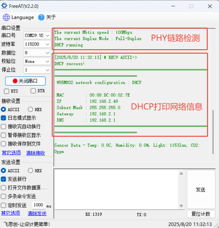
After hardware connection is complete, the following information will be printed after programming and power-on: PHY configuration and network information.
Enter 19168.2.49:8080 in your browser to access the HTML page, where you can see the sensor data change curves.
6. Summary
This project, based on the W55MH32 Ethernet microcontroller, has successfully built a multi-sensor environmental monitoring system that achieves real-time acquisition, web page visualization, and dynamic data updates of environmental parameters such as temperature, humidity, light intensity, and CO₂. The combination of a hardware TCP/IP protocol stack and an HTTP server verifies the feasibility of directly building a network monitoring platform using embedded devices, providing a reliable reference for low-cost environmental sensing solutions. Thank you for your patience in reading! If you have any questions during the reading process, or would like to learn more about this product and its applications, please feel free to leave a message via private message or in the comments section. We will reply to your message as soon as possible to provide you with more detailed answers and assistance! ————————————————
Copyright Notice: This article is an original work by CSDN blogger "Playing with Ethernet," and is licensed under CC 4.0 BY-SA. Please include the original source link and this statement when reprinting.
Original Link: https://blog.csdn.net/2301_81684513/article/details/150847414