The W5500io-M uses the TCP protocol to connect to Buffalo Cloud.
This article details how to connect to Buffalo Cloud using W5500io - M , including topic subscription and message publishing .
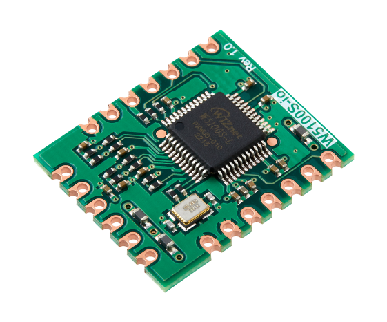
WIZnet - W5100S-io
x 1
1. Introduction
TCP (Transmission Control Protocol) is the core transport layer protocol of the Internet protocol suite, forming socket communication together with the IP protocol. Its characteristics include: establishing connection-oriented communication through a three-way handshake; achieving ordered and reliable transmission through packet numbering and automatic retransmission; using a sliding window mechanism for flow control; implementing congestion control through algorithms such as slow start; supporting bidirectional full-duplex communication; and providing byte stream services without distinguishing application layer data boundaries. TCP is widely used in scenarios such as remote monitoring data acquisition, remote equipment control, communication between IoT devices and the cloud, and embedded web server interaction. Due to its high reliability, it has become the preferred protocol for scenarios requiring stable transmission, such as financial transactions and file transfers.
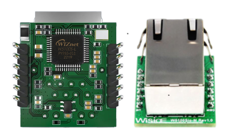
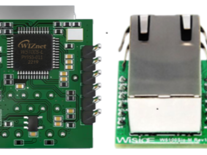
The W5500io-M is a high-performance SPI-to-Ethernet module launched by Weishi, with the following features:
Minimalist design: integrates MAC, PHY, 32KB cache and RJ45 network port, directly connects to the main controller via 4-wire SPI interface, 3.3V power supply, compact size suitable for embedded scenarios.
Simple and easy to use: Users no longer need to port the complex TCP/IP protocol stack to the MCU, and can directly develop based on application layer data.
Abundant resources: Provides a wealth of MCU application examples and hardware reference designs that can be directly referenced and used, greatly shortening the development time. Hardware is compatible with the W5100Sio-M module, facilitating solution development and iteration.
Wide range of applications: It is widely used in industrial control, smart grid, charging piles, security and fire protection, new energy, energy storage and other fields.
Product Link: Product Details
2. Project Environment
2.1 Hardware Preparation
W5500io-M module
STM32F103VCT6 Development Board
A network cable
DuPont wires
Switch or router
2.2 Software Preparation
Example program link: w5500.com/w5500.html
Development environment: Keil uVision 5
FeisiChuang Serial Port Assistant
Bafa Cloud Platform Account
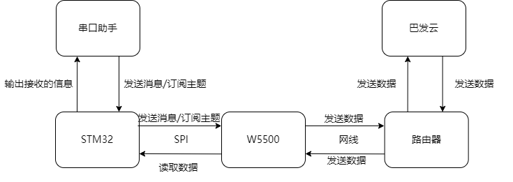
2.3 Scheme Diagram
2.4 Hardware Connection
1. //W5500_SCS ---> STM32_GPIOD7
2. //W5500_SCLK ---> STM32_GPIOB13
3. //W5500_MISO ---> STM32_GPIOB14
4. //W5500_MOSI ---> STM32_GPIOB15
5. //W5500_RESET ---> STM32_GPIOD8
6. //W5500_INT ---> STM32_GPIOD9
3. Buffalo Cloud Platform Device Creation
3.1 Creating an Account
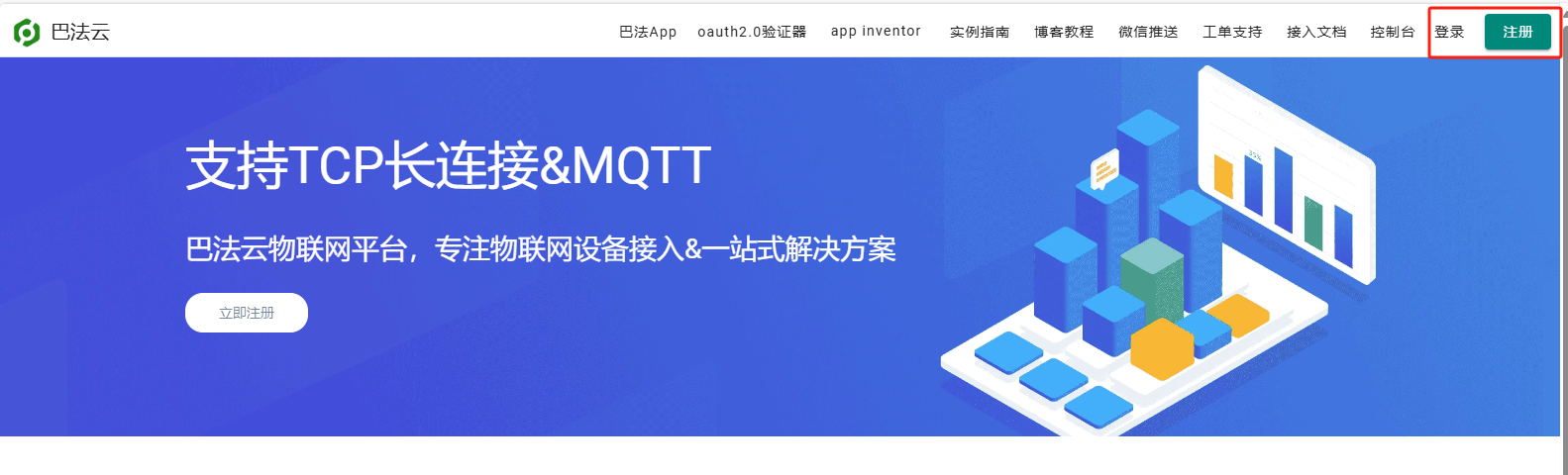
(1 ) Open the Baffa Cloud homepage: Baffa Technology & Baffa Cloud - Baffa Device Cloud - Baffa IoT Cloud Platform , log in to the Baffa Cloud platform. If you have an account, click to log in directly. If you don't have an account, register and then log in.
This cloud platform is free for individual developers and offers TCP and MQTT connection options, making it easy to quickly validate ideas and build project prototypes at low cost.
3.2 Accessing Buffalo Cloud
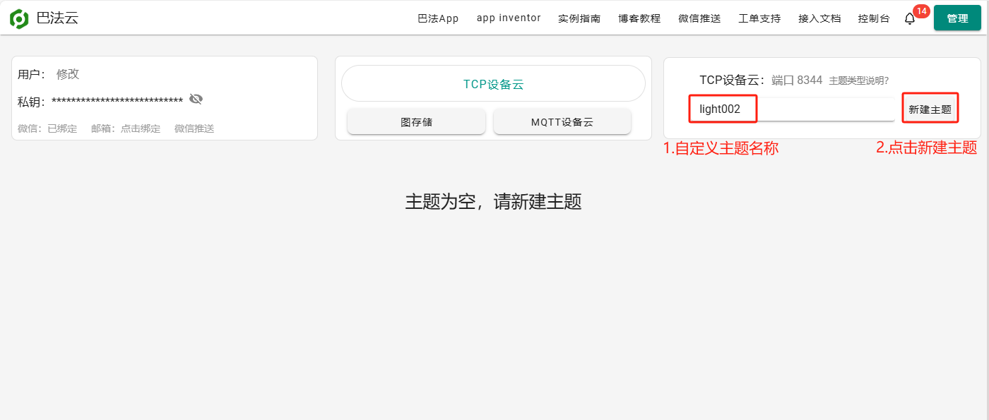
(1) Creating a topic
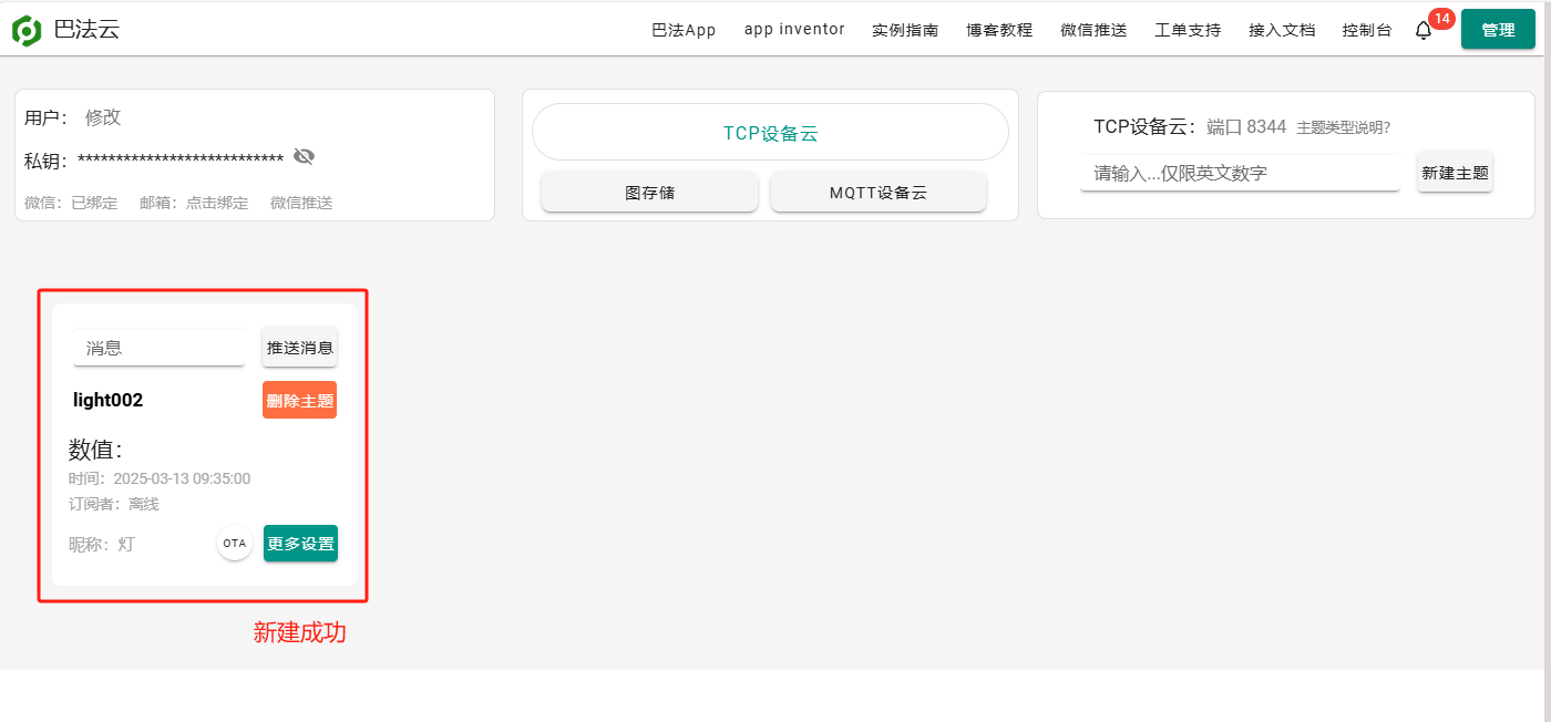
(2) Successfully created
3.3 Obtaining Network Parameters
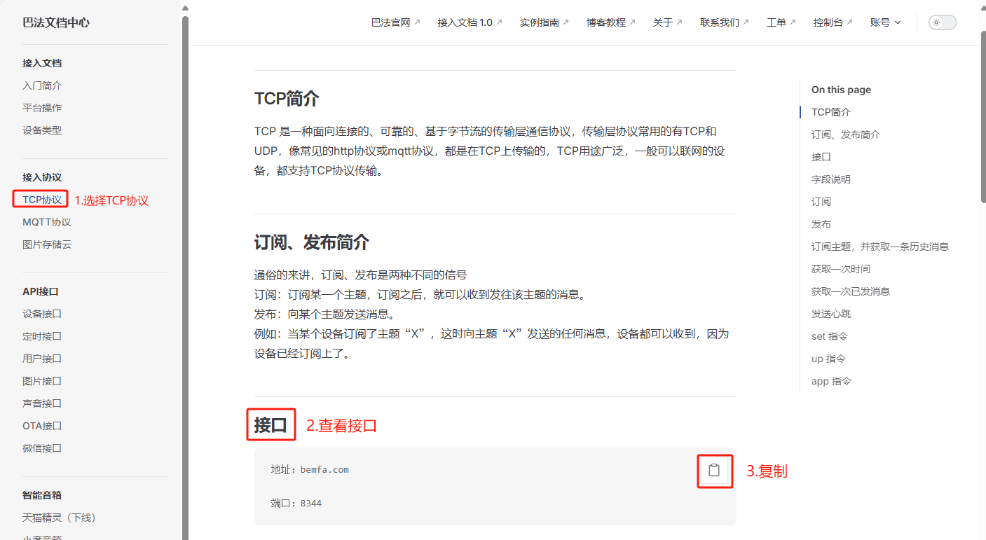
(1) Open the Bafa Cloud Documentation Center Introduction | Bafa Documentation Center , select TCP Protocol -> View Interface
The address is bemfa.com, and the DNS-resolved IP address is 119.91.109.180.
Port: 8344
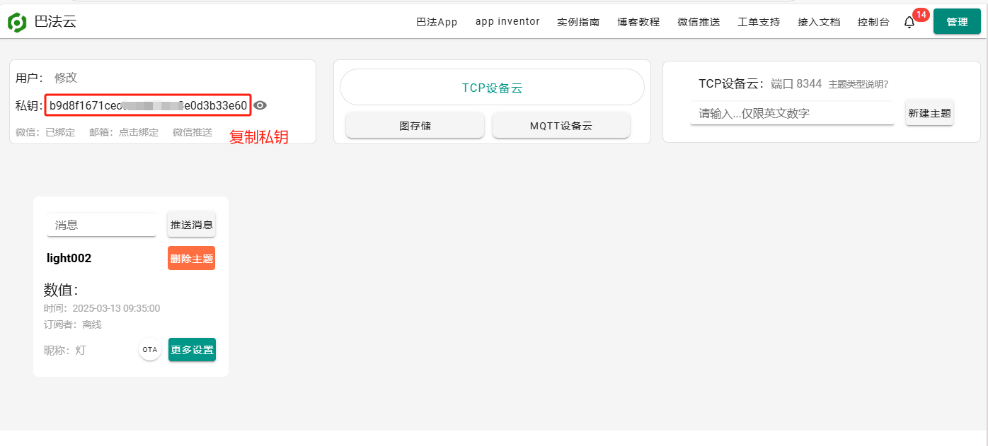
(2) Obtain the private key
The private key b9d8f1671xxxxxxxxe0d3b33e60 will be used for subscribing to topics, publishing, and sending other related information.
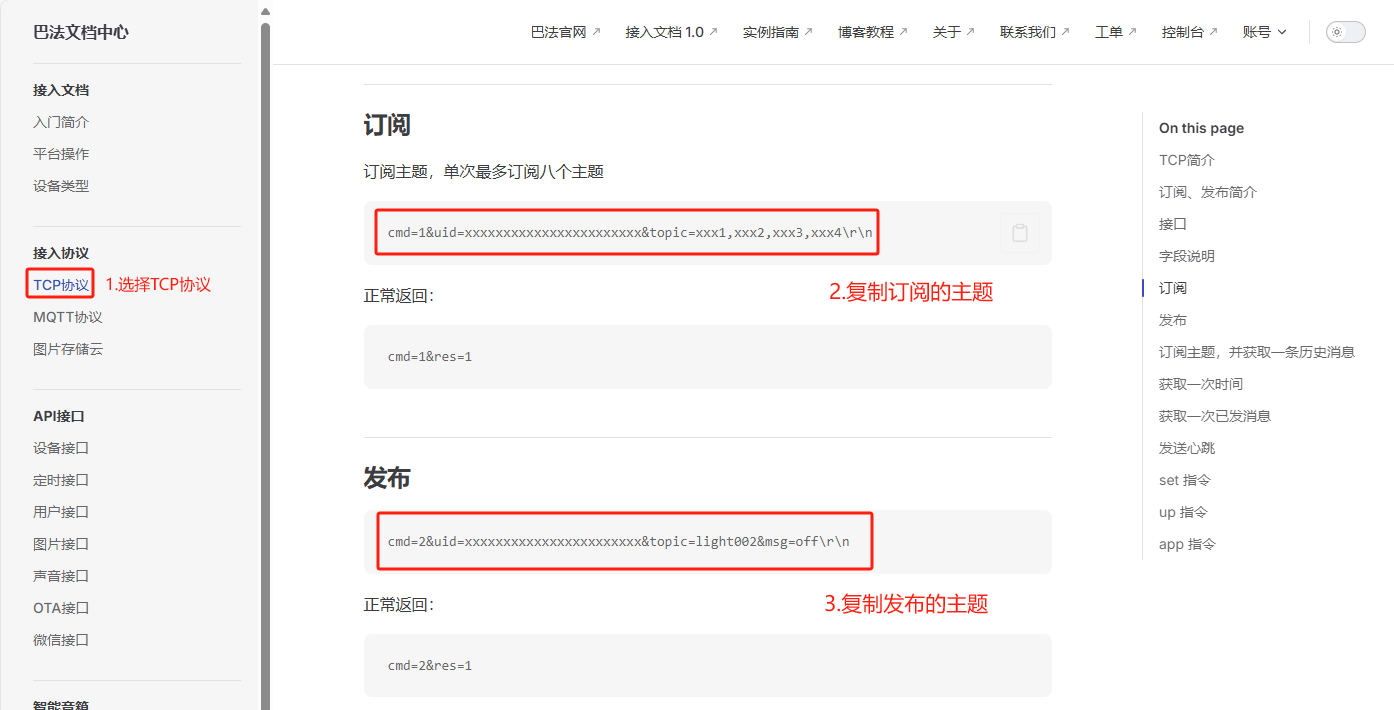
(3) Check the format of published and subscribed topics.
Replace `uid` with your private key and `topic` with your own topic. The result should look like this:
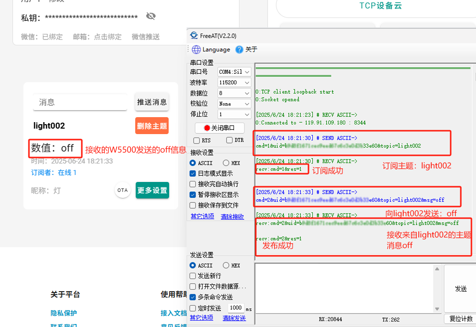
Subscribe: cmd=1&uid=b9d8f1671xxxxxxxxe0d3b33e60&topic=light002\r\n
Posted: cmd=2&uid=b9d8f1671xxxxxxxxe0d3b33e60&topic=light002&msg=off\r\n
4 routine modifications
This example uses a TCP client:
4.1 Modify main.c
Change the target IP and port parameters to the server IP address and port number of Buffalo Cloud .
uint8_t dest_ip[4] = {119, 91, 109, 180};
uint16_t dest_port = 8344;
4.2 Modify wiz_platform.c
1. Add serial port buffer and heartbeat related variables
uint8_t Serial_RxPacket[MAX_VALUE];        //串口的接收缓存
uint8_t Index=0;    //    接收索引值
uint8_t Serial_flag=0;  //接收完成标志位

uint8_t keep_live_enable=0; //心跳使能
uint16_t keep_live_time=0;  //心跳计时
uint8_t keep_live_trigger_flag=0; //心跳触发标志位
2. Enable serial port idle receive interrupt
void debug_usart_init(void)
{
   GPIO_InitTypeDef GPIO_InitStructure;
   USART_InitTypeDef USART_InitStructure;
   RCC_APB2PeriphClockCmd(RCC_APB2Periph_USART1 | RCC_APB2Periph_GPIOA, ENABLE);

   //串口1引出初始化
   GPIO_InitStructure.GPIO_Pin = GPIO_Pin_9;
   GPIO_InitStructure.GPIO_Mode = GPIO_Mode_AF_PP;
   GPIO_InitStructure.GPIO_Speed = GPIO_Speed_50MHz;
   GPIO_Init(GPIOA, &GPIO_InitStructure);
   /* Configure USART1 Rx (PA.10) as input floating */
   GPIO_InitStructure.GPIO_Pin = GPIO_Pin_10;
   GPIO_InitStructure.GPIO_Mode = GPIO_Mode_IN_FLOATING;
   GPIO_Init(GPIOA, &GPIO_InitStructure);

   //串口1参数初始化
   USART_InitStructure.USART_BaudRate = 115200;
   USART_InitStructure.USART_WordLength = USART_WordLength_8b;
   USART_InitStructure.USART_StopBits = USART_StopBits_1;
   USART_InitStructure.USART_Parity = USART_Parity_No;
   USART_InitStructure.USART_HardwareFlowControl = USART_HardwareFlowControl_None;
   USART_InitStructure.USART_Mode = USART_Mode_Rx | USART_Mode_Tx;
   USART_Init(USART1, &USART_InitStructure);

    //使能串口接收中断/空闲中断
    USART_ITConfig(USART1,USART_IT_RXNE,ENABLE);
    USART_ITConfig(USART1,USART_IT_IDLE,ENABLE);
    //中断分组
    NVIC_PriorityGroupConfig(NVIC_PriorityGroup_0);

    NVIC_InitTypeDef NVIC_InitStructure;
    NVIC_InitStructure.NVIC_IRQChannel=USART1_IRQn;
    NVIC_InitStructure.NVIC_IRQChannelCmd=ENABLE;
    NVIC_InitStructure.NVIC_IRQChannelPreemptionPriority=1;
    NVIC_InitStructure.NVIC_IRQChannelSubPriority=0;
    NVIC_Init(&NVIC_InitStructure);

  USART_Cmd(USART1, ENABLE);
}
3. Add a serial port interrupt function to receive data.
void USART1_IRQHandler(void)
{
    uint8_t Clear=0;
    if (USART_GetITStatus(USART1, USART_IT_RXNE) == SET)
    {
        Serial_RxPacket[Index++]=USART_ReceiveData(USART1);
        if(Index>=MAX_VALUE)Index=0;
        USART_ClearITPendingBit(USART1, USART_IT_RXNE);
    }
        else if(USART_GetITStatus(USART1,USART_IT_IDLE)==SET)
    {
        Serial_flag=1;
        Clear=USART1->SR;
        Clear=USART1->DR;//清除空闲中断
    }
}
4. Add functions to retrieve the serial port receive completion flag and clear the serial port receive buffer.
//获取串口接收完成标志位函数
uint8_t Serial_Receive_Flag_Complete(void)
{
    uint8_t flag=keep_live_trigger_flag;
   Serial_flag=0;
    return flag;
}
//串口接收缓存清空函数
void Serial_Receive_Clear(void)
{
    memset(Serial_RxPacket,0,sizeof(Serial_RxPacket));
    Index=0;
}
5. Add a heartbeat enable function, a function to get the heartbeat flag, and a function to clear the heartbeat time.
Baffa Cloud stipulates that if a connected device does not send any data or heartbeat data within 65 seconds, the server will proactively disconnect the connection. It's important to note that any data ending in \r\n can be considered a heartbeat message, including publish and subscribe commands. Going forward, ping\r\n will be used uniformly as the heartbeat data.
//心跳使能函数
void keep_live_enable_set(uint8_t enable)
{
    keep_live_enable=enable;
}
//获取心跳标志位函数
uint8_t keep_live_flag_get(void)
{
    uint8_t flag=keep_live_trigger_flag;
    keep_live_trigger_flag=0;
    return flag;
}
//心跳时间清空函数
void keep_live_time_clear(void)
{
    keep_live_time=0;
}
6. Add heartbeat timing function to Timer 2 interrupt function
void TIM2_IRQHandler(void)
{
    static uint32_t wiz_timer_1ms_count = 0;
    if (TIM_GetITStatus(TIM2, TIM_IT_Update) == SET)
    {
   wiz_timer_1ms_count++;
        if(keep_live_enable)
        {
       // 心跳计时
            keep_live_time++;
        }

        if (wiz_timer_1ms_count >= 1000)
   {
      DHCP_time_handler();
            wiz_timer_1ms_count = 0;
   }
         // 60秒心跳触发
        if (keep_live_time >= 60000)
   {
       keep_live_trigger_flag=1;
          keep_live_time = 0;
   }

        TIM_ClearITPendingBit(TIM2, TIM_IT_Update);
    }
}
4.3 Modify wiz_platform.h
Add receive cache declaration and function declaration
#define MAX_VALUE 2048   // 串口接收缓冲区最大长度
extern uint8_t Serial_RxPacket[];// 串口接收数据缓冲区
uint8_t Serial_Receive_Flag_Complete(void);
void Serial_Receive_Clear(void);
void keep_live_enable_set(uint8_t enable);
uint8_t keep_live_flag_get(void);
void keep_live_time_clear(void);
4.4 Replace the loopback_tcpc function
int32_t loopback_tcpc(uint8_t sn, uint8_t *buf, uint8_t *destip, uint16_t destport)
{
  int32_t ret; // 函数返回值,用于错误处理
  uint16_t size = 0;

  static uint16_t any_port = 50000; // TCP客户端端口号(会自增)

  switch (getSn_SR(sn))
  {
  case SOCK_ESTABLISHED:
        keep_live_enable_set(1);//开启心跳计时
     if (getSn_IR(sn) & Sn_IR_CON) // TCP连接中断表示与对端连接成功
     {
                 setSn_IR(sn, Sn_IR_CON); // 需要将中断位写'1'来清除
#ifdef _LOOPBACK_DEBUG_
        printf("%d:Connected to - %d.%d.%d.%d : %d\r\n", sn, destip[0], destip[1], destip[2], destip[3], destport);
#endif
     }
            if(Serial_Receive_Flag_Complete()==1)// 串口接收完成标志
            {
                    send(sn,Serial_RxPacket,strlen((char *)Serial_RxPacket));//发送接收的数据
                    Serial_Receive_Clear();        //清空缓存
                    keep_live_time_clear();    //心跳计时清0
            }

            if(keep_live_flag_get()==1)// 心跳触发标志
            {
                send(sn,(uint8_t *)"ping\r\n",6);//发送心跳包ping\r\n
            }

     if ((size = getSn_RX_RSR(sn)) > 0) // 表示待接收数据长度
     {
        if (size > DATA_BUF_SIZE)
           size = DATA_BUF_SIZE;
        ret = recv(sn, buf, size); // 数据接收过程(从硬件接收缓冲区到用户缓冲区)
        buf[size] = 0x00;          // 添加结束标志位

        if (ret <= 0)
           return ret;
              printf("recv:%s\r\n",buf);//输出接收的数据
    }
     break;

  case SOCK_CLOSE_WAIT:
#ifdef _LOOPBACK_DEBUG_
     printf("%d:CloseWait\r\n", sn);
#endif
     if ((ret = disconnect(sn)) != SOCK_OK)
        return ret;
#ifdef _LOOPBACK_DEBUG_
     printf("%d:Socket Closed\r\n", sn);
#endif
     break;

  case SOCK_INIT:

     if ((ret = connect(sn, destip, destport)) != SOCK_OK)// 尝试TCP连接到目标服务器
        return ret;
     break;

  case SOCK_CLOSED:
     close(sn);
     if ((ret = socket(sn, Sn_MR_TCP, any_port++, 0x00)) != sn)// 使用'any_port'端口号打开TCP套接字
     {
        if (any_port == 0xffff)
           any_port = 50000;
        return ret;
     }
#ifdef _LOOPBACK_DEBUG_
     printf("%d:TCP client loopback start\r\n", sn);
     printf("%d:Socket opened\r\n", sn);
#endif
     break;
  default:
     break;
  }
  return 1;
}
5 Functional Verification
(1 ) Phenomenon after burning the program : First, the PHY link will be detected to confirm that the physical layer connection status is normal and to ensure the basic conditions for network communication. After the detection is passed, the system will print out the network address information that has been set, so that users can confirm whether the network configuration is correct. Finally, it will connect to Baffa Cloud.
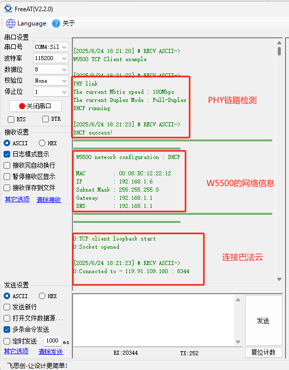
(2 ) Using a serial port assistant , first send a data packet to subscribe to the topic "light002". After successful subscription, send an "off" message to the topic "light002". Subsequently, receive an " off" message from the topic "light002" .