
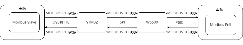
STM32+W5500 for Modbus RTU and Modbus TCP conversion
STM32+W5500 for Modbus RTU and Modbus TCP conversion
1. Introduction
Modbus RTU
Based on serial communication (such as RS-485), it uses a master-slave query-response mode. Data is transmitted in binary format, with each byte containing 1 start bit, 8 data bits, 1 parity bit (optional), and 1 stop bit. There is no fixed frame header/tail; frame boundaries are distinguished by time intervals (typically 3.5 character times). Its advantages are low hardware cost and strong anti-interference capabilities, making it suitable for short-distance, low-speed scenarios (such as sensor networks), but strict timing control is required when there are multiple slaves.
Modbus TCP
Based on Ethernet (TCP/IP protocol), Modbus messages are encapsulated in TCP frames, and devices are identified by IP address and port number. Data is transmitted in plaintext binary, including an MBAP header (transaction identifier, protocol identifier, etc.), and no check bit is required (relying on TCP reliability). Its advantages are high transmission rate and support for remote access, making it suitable for distributed systems (such as factory automation), but network infrastructure support is required.
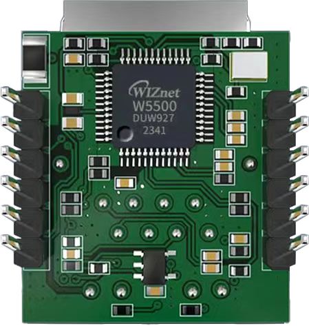
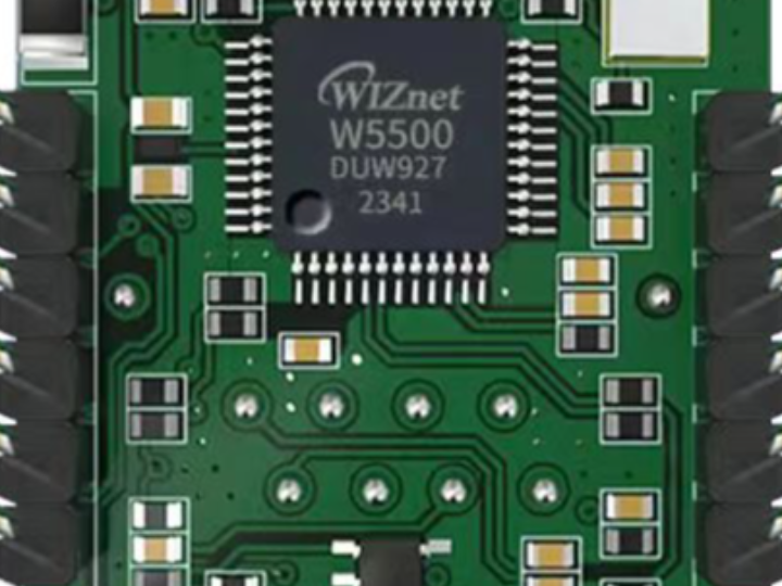
The W5500io-M is a high-performance SPI-to-Ethernet module from W5500io-M, featuring the following characteristics:
Simple Design: Integrates MAC, PHY, 32KB buffer, and RJ45 Ethernet port. It connects directly to the main controller via a 4-wire SPI interface, operates on 3.3V power, and its compact size is suitable for embedded systems.
Easy to Use: Users no longer need to port complex TCP/IP protocol stacks to the MCU; they can directly develop based on application-layer data.
Rich Documentation: Provides abundant MCU application examples and hardware reference designs for direct reference, significantly shortening development time. Hardware compatibility with the W5100Sio-M module facilitates solution development and iteration.
Wide Applications: Widely used in industrial control, smart grids, charging piles, security and fire protection, new energy, and energy storage.
Product Link: Product Details
2. Project Environment
2.1 Hardware Preparation
W5500io-M module
STM32F103VCT6 development board
One network cable
Several DuPont wires
2.2 Software Preparation
Example link: w5500.com/w5500.html
Development environment: Keil uVision 5
Freescale Serial Port Assistant
Network Debugging Assistant
Modbus Slave
Modbus Poll
2.3 Scheme Diagram
2.4 Hardware Connections
1. //W5500_SCS ---> STM32_GPIOD7 /*W5500's chip select pin*/
2. //W5500_SCLK ---> STM32_GPIOB13 /*W5500's clock pin*/
3. //W5500_MISO ---> STM32_GPIOB14 /*W5500's MISO pin*/
4. //W5500_MOSI ---> STM32_GPIOB15 /*W5500's MOSI pin*/
5. //W5500_RESET ---> STM32_GPIOD8 /*W5500's RESET pin*/
6. //W5500_INT ---> STM32_GPIOD9 /*The INT pin of W5500*/
3 Modbus Slave
3.1 Software Introduction
Modbus Slave is a software tool that simulates Modbus slave devices. It supports multiple protocols such as Modbus RTU/ASCII/TCP, and can create multiple virtual slaves, facilitating communication testing and debugging with the master device. It helps developers quickly verify the functionality of Modbus master programs, improving development efficiency.
3.2 Function Introduction
3.2.1 Establishing a Connection
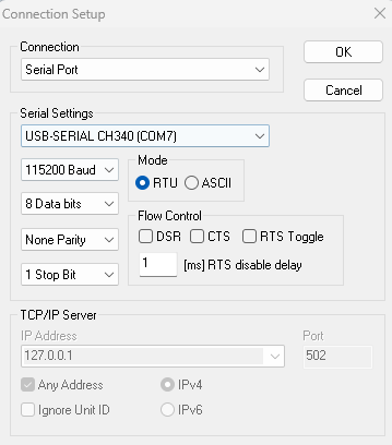
Click "Connection" -> "Connect..." in the menu bar (or press the shortcut key F3) to bring up the connection configuration window.
In the connection options, select "Serial Port" to indicate that serial communication is currently used. If Modbus/TCP is used, select "TCP/IP".
3.2.2 Serial Port Configuration
In the configuration window, configure the port number, baud rate, data bits, parity bits, and stop bits. Here, I'm using a baud rate of 115200, 8 data bits, no parity, and 1 stop bit. In actual use, the settings need to be matched according to the slave device being communicated with.
3.2.3 Configuration Window Information
Click "Setup" -> "Slave Definition...", or press the shortcut key F8, or right-click in the window where you want to configure and select "Slave Definition..." to open the configuration window information interface.
Slave ID: Configures the slave address.
Function: Configures the register/coil type.
Address: Configures the starting address of the register/coil to be read/written.
Quantity: Configures the number of registers/coils to be read/written.
Rows: Selects how many rows to display in a column of this window. The number represents the row number. The last option, "Fit to Quantity," automatically matches the row number based on the previously set "Quantity."
Hide Alias Columns: Allows you to choose whether to hide the "Alias" column.
PLC Addresses (Base 1): Allows you to choose whether the communication base address starts from 0 or 1.
3.2.4 Window Operations
Double-clicking the data location allows you to modify the register/coil value at the current address.
4. Modbus Poll
4.1 Software Introduction
Modbus Poll is a Windows-based Modbus master testing tool used to simulate and monitor Modbus RTU/TCP communication. It supports reading and writing registers (such as coils, input registers, holding registers, etc.) of slave devices, displays data changes in real time, and provides logging, data charts, and error detection functions. It is widely used in industrial automation, PLC debugging, and equipment testing.
4.2 Function Introduction
4.2.1 Establishing a Connection
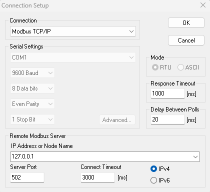
Click "Connection" -> "Connect..." (or press the shortcut key F3) in the menu bar to bring up the connection configuration window. Select "Modbus TCP/IP" in the connection options to select Modbus TCP communication.
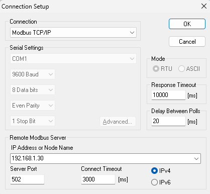
4.2.2 Server Parameter Configuration
Set the IP address and port number. The default port number for Modbus/TCP is 502. The actual port number should be set according to the IP address and port number of the slave device. Set the connection timeout; the default 3000ms is generally sufficient.
4.2.3 Configuring Window Information
Click "Setup" -> "Read/Write Definition...", or press the shortcut key F8, or right-click the window you want to configure and select "Read/Write Definition..." to open the window information configuration interface.
Slave ID: Configures the slave address
Function: Configures the function code
Address: Configures the start address of the register/coil to be read/written
Quantity: Configures the number of registers/coils to be read/written
Scan Rate: Configures the frame scan period
5. Modbus RTU to Modbus TCP Data Conversion Method
5.1 Modbus RTU Frame Structure
Data Frame Structure: [Slave Address][Function Code][Data][CRC Checksum]
Example: 01 03 00 00 00 02 C4 0B
01: Slave Address (Device 1)
03: Function Code (Read Holding Register)
00 01: Start Register Address (0001)
00 02: Number of Registers Read (2)
C4 0B: CRC16 Checksum
5.2 Modbus TCP Frame Structure
Data Frame Structure: [Transaction Identifier][Protocol Identifier][Length][Unit Identifier][Function Code][Data]
Example: 00 01 00 00 00 06 01 03 00 00 00 02
00 01: Transaction Identifier (Customizable)
00 00: Protocol Identifier (Fixed)
00 06: Number of Subsequent Bytes (6 bytes)
01: Unit Identifier (Device 1, equivalent to slave address)
03: Function Code (Read Holding Register)
00 01 00 02: Data (Same as RTU)
5.3 Method for Converting Modbus RTU to Modbus TCP
5.3.1 Removing CRC Checksum
Original Data Frame: 01 03 00 00 00 02 C4 0B
After Removing CRC: 01 03 00 00 00 02
5.3.2 Adding MBAP Header
Transaction Identifier (incrementable): 00 01
Protocol Identifier (fixed): 00 00
Length (Number of Subsequent Bytes): 00 06 (1+1+4)
Unit Identifier (Same as RTU Address): 01
5.3.3 Assembling into a TCP Frame
Final Modbus TCP Frame: 00 01 00 00 00 06 01 03 00 00 00 025.4 Method for Converting Modbus TCP to Modbus RTU
5.4.1 Removing the MBAP Header
Original Mosbus TCP Data Frame: 00 01 00 00 00 06 01 03 00 00 00 02
After Removing the MBAP: 01 03 00 00 00 02
5.4.2 Calculating the CRC Checksum and Appending it to the End
Calculate the CRC16 of 01 03 00 01 00 02 (result is C4 0B)
Final Mosbus RTU Frame: [01][03][00][01][00][02][C4][0B]
6. Example Modifications
This example uses a TCP server:
6.1 Modifying wiz_platform.c
1. Adding a serial port buffer variable
uint8_t Serial_RxPacket[MAX_VALUE]; // Serial port receive buffer
uint8_t Index=0; // Receive index
uint8_t Serial_flag=0; // Receive completion flag
2. Add a serial port 2 initialization function for communication with the Modbus Slave.
void Serial2_Init(void)
{
/* Enable clock */
RCC_APB1PeriphClockCmd(RCC_APB1Periph_USART2, ENABLE); // Enable the clock for USART1
RCC_APB2PeriphClockCmd(RCC_APB2Periph_GPIOA, ENABLE); // Enable the clock for GPIOA
/* GPIO initialization */
GPIO_InitTypeDef GPIO_InitStructure;
GPIO_InitStructure.GPIO_Mode = GPIO_Mode_AF_PP;
GPIO_InitStructure.GPIO_Pin = GPIO_Pin_2;
GPIO_InitStructure.GPIO_Speed = GPIO_Speed_50MHz;
GPIO_Init(GPIOA, &GPIO_InitStructure); // Initialize PA9 pin as a push-pull output
GPIO_InitStructure.GPIO_Mode = GPIO_Mode_IPU;
GPIO_InitStructure.GPIO_Pin = GPIO_Pin_3;
GPIO_InitStructure.GPIO_Speed = GPIO_Speed_50MHz;
GPIO_Init(GPIOA, &GPIO_InitStructure); // Initialize PA10 pin as a pull-up input
/*USART initialization*/
USART_InitTypeDef USART_InitStructure; // Define structure variables
USART_InitStructure.USART_BaudRate = 115200; // Baud rate USART_InitStructure.USART_HardwareFlowControl = USART_HardwareFlowControl_None; // Hardware flow control, not needed
USART_InitStructure.USART_Mode = USART_Mode_Tx | USART_Mode_Rx; // Mode, select both transmit and receive modes
USART_InitStructure.USART_Parity = USART_Parity_No; // Parity check, not needed
USART_InitStructure.USART_StopBits = USART_StopBits_1; // Stop bits, select 1 bit
USART_InitStructure.USART_WordLength = USART_WordLength_8b; // Word length, select 8 bits
USART_Init(USART2, &USART_InitStructure); // Pass the structure variable to USART_Init, configure USART1
// Enable serial port receive interrupt/idle interrupt
USART_ITConfig(USART2,USART_IT_RXNE,ENABLE);
USART_ITConfig(USART2,USART_IT_IDLE,ENABLE);
/ // Interrupt grouping
NVIC_PriorityGroupConfig(NVIC_PriorityGroup_0);
NVIC_InitTypeDef NVIC_InitStructure;
NVIC_InitStructure.NVIC_IRQChannel=USART2_IRQn;
NVIC_InitStructure.NVIC_IRQChannelCmd=ENABLE;
NVIC_InitStructure.NVIC_IRQChannelPreemptionPriority=1;
NVIC_InitStructure.NVIC_IRQChannelSubPriority=0;
NVIC_Init(&NVIC_InitStructure); /* Enable USART */
USART_Cmd(USART2, ENABLE); // Enable USART1, serial port starts running
}3. Add a function to receive data via serial port 2 interrupt.
void USART2_IRQHandler(void)
{
uint8_t Clear=0;
if (USART_GetITStatus(USART2, USART_IT_RXNE) == SET)    //Check if the interrupt was triggered by a USART2 receive event
{
uint8_t data=USART_ReceiveData(USART2);
Serial_RxPacket[Index++]=data;
if(Index>=MAX_VALUE)Index=0;
USART_ClearITPendingBit(USART2, USART_IT_RXNE);        //Clear the flag
}
else if(USART_GetITStatus(USART2,USART_IT_IDLE)==SET)//If an idle interrupt occurred
{
Serial_flag=1;
Clear = USART2->SR;
Clear = USART2->DR; // Clear idle interrupts
}
}
4. Add a function to send hex data via serial port 2 to send Modbus RTU data frames.
void USART2_SendByte(uint8_t data)
{
// Wait for the send buffer to be empty
while (USART_GetFlagStatus(USART2, USART_FLAG_TXE) == RESET);
// Send data
USART_SendData(USART2, data);
}
void USART2_SendHexArray(uint8_t *data, uint8_t length)
{
for (uint8_t i = 0; i < length; i++) {
USART2_SendByte(data[i]);
}
}
5. Add functions to retrieve the serial port receive completion flag, clear the serial port receive buffer, and retrieve the length of the received serial port data.
// Function to get the serial port receive completion flag
uint8_t Serial_Receive_Flag_Complete(void)
{
uint8_t flag=keep_live_trigger_flag;
Serial_flag=0;
return flag;
}
// Function to clear the serial port receive buffer
void Serial_Receive_Clear(void)
{
memset(Serial_RxPacket,0,sizeof(Serial_RxPacket));
Index=0;
}
// Function to get the serial port data received length
uint16_t Serial_Receive_len(void)
{
return index;
}
6.2 Modify wiz_platform.h
Add receive buffer declaration and function declaration
#define MAX_VALUE 2048 // Maximum length of serial port receive buffer
extern uint8_t Serial_RxPacket[];// Serial port receive data buffer
void Serial2_Init(void);
uint16_t Serial_Receive_len(void);
uint8_t Serial_Receive_Flag_Complete(void);
void Serial_Receive_Clear(void);
void USART2_SendHexArray(uint8_t *data, uint8_t length);
6.3 Modify loopback.c
1. Added host-to-network sequence macro definition, Modbus RTU buffer, and defined Modbus TCP data frame structure.
#define htons(x) ((uint16_t)((((x) << 8) & 0xFF00) | (((x) >> 8) & 0xFF)))// Host order to network order macro definition (16-bit)
uint8_t rtu_buf[256]; // Modbus RTU frame buffer
typedef struct __attribute__((packed)) {
uint16_t transaction_id; // Transaction identifier (used for request/response matching)
uint16_t protocol_id; // Protocol identifier (fixed 0x0000)
uint16_t length; // Subsequent data length (including unit ID)
uint8_t unit_id; // Device address (equivalent to RTU slave address)
uint8_t data[256]; // Function code + data (excluding CRC)
} ModbusTCP_Frame;
2. Add Modbus CRC16 checksum calculation function
uint16_t modbus_crc16(const uint8_t *data, uint16_t length)
{
   uint16_t crc = 0xFFFF;
   for(uint16_t i = 0; i < length; i++) {
       crc ^= data[i];
       for(uint8_t j = 0; j < 8; j++) {
           if(crc & 0x0001) {
               crc = (crc >> 1) ^ 0xA001;
           } else {
               crc >>= 1;
           }
       }
   }
   return crc;
}
3. Add a function to print Modbus TCP frames.
void print_modbus_tcp_frame(const ModbusTCP_Frame *frame, uint16_t tcp_len)
{
   printf("rtu_to_tcp Frame: ");
   const uint8_t *p = (const uint8_t *)frame;
   for (uint16_t i = 0; i < tcp_len; i++) {
       printf("%02X ", p[i]);
   }
   printf("\r\n");
}
4. Add Modbus RTU to TCP function
uint16_t rtu_to_tcp(const uint8_t *rtu_data, uint16_t rtu_len, ModbusTCP_Frame *tcp_frame, uint16_t received_tid) {
if (rtu_len < 4) return 0;
/ // 1. Calculate the length of valid data (excluding address 1 + function code 1 + CRC2)
uint16_t data_len = rtu_len - 4;
/ // 2. Set the MBAP header (reuse the received Transaction ID)
tcp_frame->transaction_id = htons(received_tid);; // Directly use the passed-in TID (ensure it is in network byte order)
tcp_frame->protocol_id = htons(0x0000); // Protocol ID is fixed at 0
tcp_frame->length = htons(1 + 1 + data_len); // Unit ID 1 + function code 1 + Data_len
/ 3. Copy unit ID and function code + data
tcp_frame->unit_id = rtu_data[0]; // Unit ID
tcp_frame->data[0] = rtu_data[1]; // Function code
memcpy(&tcp_frame->data[1], &rtu_data[2], data_len); // Data part
/ 4. Return total length = MBAP6 + Unit ID1 + Function code1 + Data_len
return 6 + 1 + 1 + data_len;
}
5. Add Modbus TCP to RTU function
uint16_t tcp_to_rtu(const uint8_t *tcp_data, uint16_t tcp_len, uint8_t *rtu_buf)
{
if (tcp_len < 8) return 0; // Minimum length check (MBAP7 + function code 1)

// Extract unit ID (RTU device address)
rtu_buf[0] = tcp_data[6]; // MBAP byte 7 is unit ID

// Copy function code + data (skip MBAP header)
uint16_t data_len = tcp_len - 7;
memcpy(&rtu_buf[1], &tcp_data[7], data_len);

// Calculate and append CRC16 checksum
uint16_t crc = modbus_crc16(rtu_buf, data_len + 1);
rtu_buf[data_len + 1] = crc & 0xFF; // CRC low byte
rtu_buf[data_len + 2] = crc >> 8; // CRC high byte
return data_len + 3; // Address 1 + Data(N) + CRC2
}
6. Replace the loopback_tcpc function
int32_t loopback_tcps(uint8_t sn, uint8_t *buf, uint16_t port)
{
int32_t ret; // Function return value, used for error handling
uint16_t size = 0; // Length of received data
static uint16_t received_tid=0; // Static variable to store transaction ID (value retained across function calls)
#ifdef _LOOPBACK_DEBUG_
uint8_t destip[4];
uint16_t destport;
#endif
switch (getSn_SR(sn))
{
case SOCK_ESTABLISHED:
if (getSn_IR(sn) & Sn_IR_CON) // TCP connection interruption indicates successful connection with the peer
{
setSn_IR(sn, Sn_IR_CON); // Need to write '1' to clear the interrupt bit
#ifdef _LOOPBACK_DEBUG_
getSn_DIPR(sn, destip);
destport = getSn_DPORT(sn);
printf("%d:Connected - %d.%d.%d.%d : %d\r\n", sn, destip[0], destip[1], destip[2], destip[3], destport);
#endif
}
if ((size = getSn_RX_RSR(sn)) > 0) // Indicates the length of the data to be received
{
if (size > DATA_BUF_SIZE)
size = DATA_BUF_SIZE;
ret = recv(sn, buf, size); // Data reception process (from hardware receive buffer to user buffer)
buf[size] = 0x00; // Add end flag

if (ret <= 0)
return ret;
received_tid = (buf[0] << 8) | buf[1];//Transaction identifier of the received TCP frame
uint16_t rtu_len = tcp_to_rtu(buf, size, rtu_buf); // Convert the TCP frame to an RTU frame
printf("tcp_to_rtu Frame: ");
for (uint16_t i = 0; i < rtu_len; i++)
{
printf("%02X ", rtu_buf[i]);
}
USART2_SendHexArray(rtu_buf,rtu_len);
}

if(Serial_Receive_Flag_Complete()==1)
{
uint16_t len=Serial_Receive_len();// Get serial port data length
ModbusTCP_Frame tcp_frame;
printf("Modbus RTU Frame: ");
for(uint16_t i=0;i<len;i++)// Print the sent Modbus RTU data frame
{
printf("%02X ",Serial_RxPacket[i]);
}
printf("\r\n");
// Extract the CRC from the Modbus RTU data
uint16_t received_crc = (Serial_RxPacket[len - 1] << 8) | Serial_RxPacket[len - 2];
uint16_t calculated_crc = modbus_crc16(Serial_RxPacket, len-2);//Calculate CRC
if(received_crc==calculated_crc)//Check CRC
{
/ Convert RTU frames to TCP frames (reusing previously received transaction IDs)
uint16_t tcp_len = rtu_to_tcp(Serial_RxPacket, len, &tcp_frame, received_tid);
print_modbus_tcp_frame(&tcp_frame, tcp_len);// Print the sent Modbus TCP data frame
send(sn,(uint8_t *)&tcp_frame,tcp_len) ;// Send Modbus TCP data frame
else
{
printf("CRC validation failed ")
}
Serial_Receive_Clear();//Clear the serial port cache
}
break;
case SOCK_CLOSE_WAIT:
#ifdef _LOOPBACK_DEBUG_
printf("%d:CloseWait\r\n", sn);
#endif
if ((ret = disconnect(sn)) != SOCK_OK)
return ret;
#ifdef _LOOPBACK_DEBUG_
printf("%d:Socket Closed\r\n", sn);
#endif
break;
case SOCK_INIT:
#ifdef _LOOPBACK_DEBUG_
printf("%d:Listen, TCP server loopback, port [%d]\r\n", sn, port);
#endif if ((ret = listen(sn)) != SOCK_OK)
return ret;
break;
case SOCK_CLOSED:
#ifdef _LOOPBACK_DEBUG_
printf("%d:TCP server loopback start\r\n", sn);
#endif
if ((ret = socket(sn, Sn_MR_TCP, port, 0x00)) != sn)
return ret;
#ifdef _LOOPBACK_DEBUG_
printf("%d:Socket opened\r\n", sn);
#endif
break;
default:
break;
}
return 1;
}
7. Functional Verification
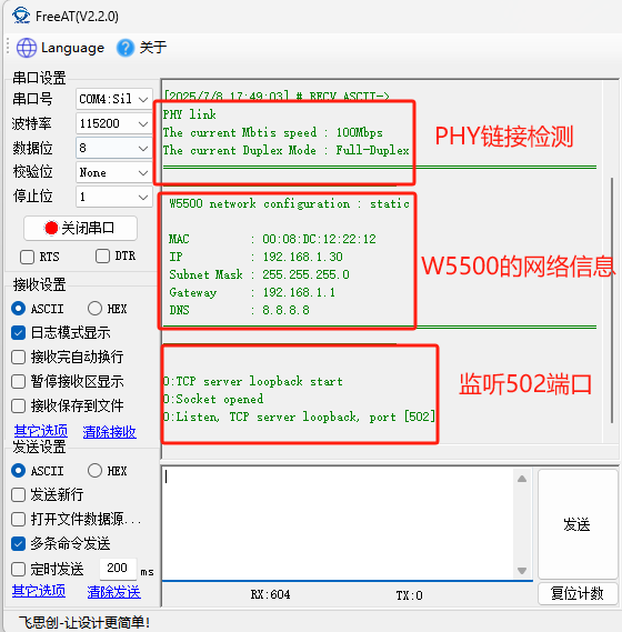
(1) Phenomenon after program burning: First, a PHY link test is performed to confirm the physical layer connection status is normal, ensuring the basic conditions for network communication; after the test passes, the system prints out the configured network address information to confirm whether the network configuration is correct; finally, it listens on port 502 for client connections.
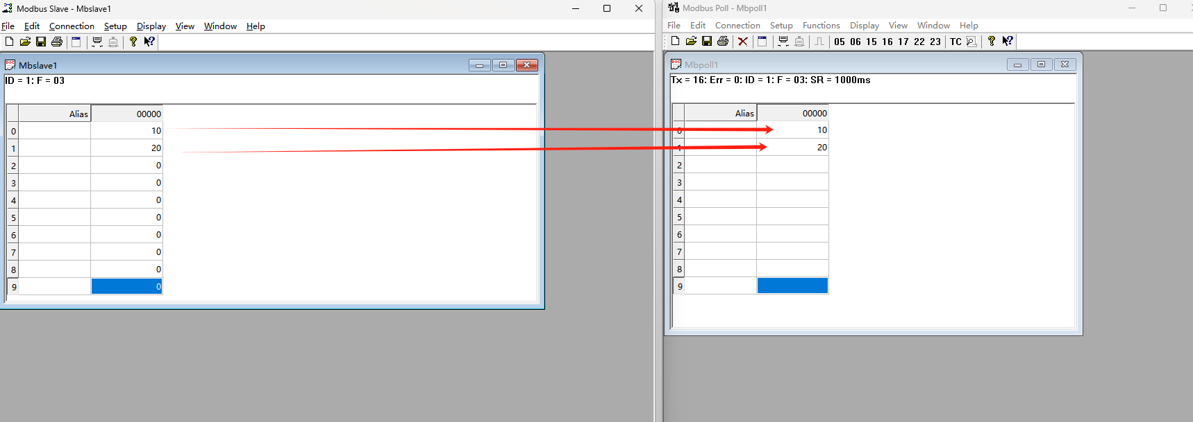
(2) Use Modbus Poll to connect to W5500 for communication.
(3) Data acquisition successful.
8. Summary
This article details how to use W5500io-M to achieve mutual conversion between Modbus RTU and Modbus TCP. Thank you for reading! If you have any questions about this article, or would like to learn more about this product, please feel free to leave a message via private message or in the comments section, and we will reply to your message as soon as possible!
———————————————— Copyright Notice: This article is an original article by CSDN blogger "Playing with Ethernet", and follows the CC 4.0 BY-SA copyright agreement. Please include the original source link and this statement when reprinting. Original link: https://blog.csdn.net/2301_81684513/article/details/149244032