
Implementing a FatFs file system + FTP server based on W55MH32Q-EVB
Implementing a FatFs file system + FTP server based on W55MH32Q-EVB
1. Introduction
FTP (File Transfer Protocol) is an important component that provides file transfer services over a network, adhering to the File Transfer Protocol (FTP). It adopts a client-server architecture and operates in two modes: active and passive. In active mode, the server initiates the data connection; in passive mode, the client initiates the connection. User authentication is required upon access, commonly through a username and password, although some servers also support anonymous login.
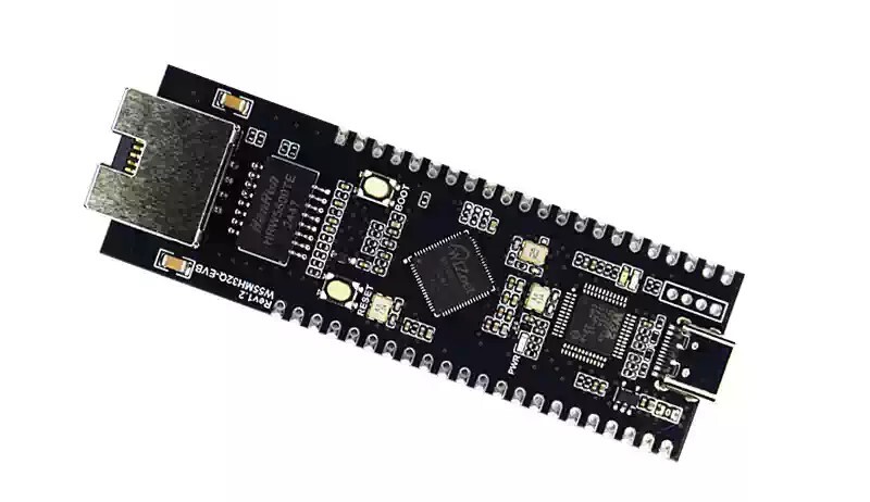
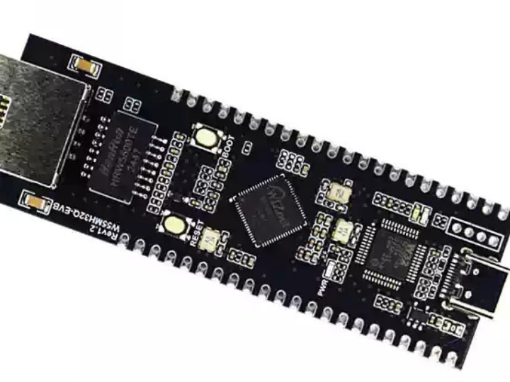
The W55MH32Q-EVB is a development board based on the W55MH32Q chip. It features a 216MHz clock speed, 1MB of flash memory, and 96KB of SRAM. It also includes a complete hardware TCP/IP offloading engine, allowing for Ethernet applications to be implemented with simple socket programming. Features include:
Enhanced, true random number generation, hardware encryption algorithm unit
On-chip 32-bit Arm® Cortex®-M3 core
Microcontroller with 1024KB Flash memory
10/100M Ethernet MAC and PHY, integrated full-hardware TCP/IP protocol stack engine
USB, CAN, 17 timers
3 ADCs, 2 DACs, 12 communication interfaces
Product Link: Product Details
2 Project Environment
2.1 Hardware Preparation
- W55MH32Q-EVB module
- Several DuPont wires
- Switch or router
- W25Q64 module
- One network cable
2.2 Software Environment
- Example Link: https://www.w5500.com/w55mh32.html
- FreeAT_2.2.0.0.exe
- Keil5
- FatFs source code
3 Hardware Connection and Solution
3.1 W55MH32Q-EVB Hardware Connections
1. W55MH32Q-EVB_3.3V ---> W25Q64_VCC
2. W55MH32Q-EVB_GND ---> W25Q64_GND
3. W55MH32Q-EVB_PA4 ---> OLED_CS
4. W55MH32Q-EVB_PA5 ---> OLED_SCK
5. W55MH32Q-EVB_PA6 ---> OLED_MISO
6. W55MH32Q-EVB_PA7 ---> OLED_MOSI
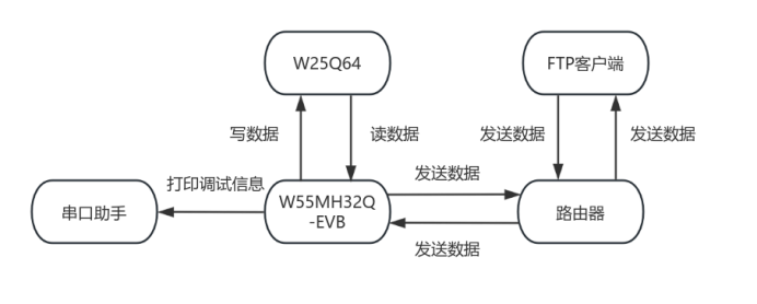
3.2 Solution Diagram
4 Example Modification
This example uses the FTP_Server program.
Because the ftp.c file is quite long, has many modifications, and is scattered, I have uploaded it to Baidu Cloud. Access the link to obtain the ftpd.c file.
Replace the ftpd.c file in the example program with the downloaded file, and enable the macro definition F_FILESYSTEM in ftpd.h.
Create the file w25qxx.c to drive the W25Q64, the code is as follows:
#include "w25qxx.h"
#include "delay.h"

u16 W25QXX_TYPE = W25Q128; // The default is W25Q128.

// SPIx reads and writes a byte
// TxData: Bytes to write
// Return value: bytes read
u8 SPI_ReadWriteByte(u8 TxData)
{
   u8 retry = 0;
   while (SPI_I2S_GetFlagStatus(SPI1, SPI_I2S_FLAG_TXE) == RESET) // Check whether the specified SPI flag is set or not: Send cache null flag
   {
       retry++;
       if (retry > 200)
           return 0;
   }
   SPI_I2S_SendData(SPI1, TxData); // Send a data via peripheral SPIx
   retry = 0;

   while (SPI_I2S_GetFlagStatus(SPI1, SPI_I2S_FLAG_RXNE) == RESET) // Check whether the specified SPI flag is set or not: Accept cache non-empty flags
   {
       retry++;
       if (retry > 200)
           return 0;
   }
   return SPI_I2S_ReceiveData(SPI1); // Returns the most recently received data via SPIx
}

void SPI_InitTest(void)
{
   GPIO_InitTypeDef GPIO_InitStructure;
   SPI_InitTypeDef SPI_InitStructure;

   RCC_APB2PeriphClockCmd(RCC_APB2Periph_GPIOA, ENABLE); // PORT Aclock enable
   RCC_APB2PeriphClockCmd(RCC_APB2Periph_SPI1, ENABLE);  // SPI1 clock enable

   GPIO_InitStructure.GPIO_Pin = GPIO_Pin_4;
   GPIO_InitStructure.GPIO_Mode = GPIO_Mode_Out_PP;
   GPIO_InitStructure.GPIO_Speed = GPIO_Speed_50MHz;
   GPIO_Init(GPIOA, &GPIO_InitStructure);
   GPIO_SetBits(GPIOA, GPIO_Pin_4);

   W25QXX_CS = 1; // SPI FLASH not selected

   GPIO_InitStructure.GPIO_Pin = GPIO_Pin_5 | GPIO_Pin_6 | GPIO_Pin_7;
   GPIO_InitStructure.GPIO_Mode = GPIO_Mode_AF_PP; // PA/5/6/7 Multiplexed push-pull output
   GPIO_InitStructure.GPIO_Speed = GPIO_Speed_50MHz;
   GPIO_Init(GPIOA, &GPIO_InitStructure); // Initialize GPIOA

   GPIO_SetBits(GPIOA, GPIO_Pin_5 | GPIO_Pin_6 | GPIO_Pin_7); // PA5/6/7 pull up

   SPI_InitStructure.SPI_Direction = SPI_Direction_2Lines_FullDuplex;   // Set SPI to one-way or two-way data mode: SPI is set to 2 lines full duplex
   SPI_InitStructure.SPI_Mode = SPI_Mode_Master;                        // Set SPI working mode: Set the Master
   SPI_InitStructure.SPI_DataSize = SPI_DataSize_8b;                    // Set the data size of the SPI: SPI sends and receives 8-bit frame structures
   SPI_InitStructure.SPI_CPOL = SPI_CPOL_High;                          // The idle state of the serial synchronous clock is high
   SPI_InitStructure.SPI_CPHA = SPI_CPHA_2Edge;                         // The second hop edge (up or down) of the serial synchronization clock is sampled
   SPI_InitStructure.SPI_NSS = SPI_NSS_Soft;                            // NSS signals are managed by hardware (NSS pins) or software (using SSI bits): Internal NSS signals are controlled by SSI bits
   SPI_InitStructure.SPI_BaudRatePrescaler = SPI_BaudRatePrescaler_256; // Define the value of the baud rate prescaler: The baud rate prescaler is 256.
   SPI_InitStructure.SPI_FirstBit = SPI_FirstBit_MSB;                   // Specify whether the data transfer starts with the MSB bit or the LSB bit: Data transfer starts with the MSB bit
   SPI_InitStructure.SPI_CRCPolynomial = 7;                             // Polynomial for CRC Value Calculation
   SPI_Init(SPI1, &SPI_InitStructure);                                  // Initializes peripheral SPIx registers according to the parameters specified in the SPI_InitStruct

   SPI_Cmd(SPI1, ENABLE); // enable SPI peripherals

   SPI_ReadWriteByte(0xff); // Initiate transfer
}
// SPI speed setting function
// SpeedSet:
// SPI_BaudRatePrescaler_2   2 division
// SPI_BaudRatePrescaler_8   8 division
// SPI_BaudRatePrescaler_16  16 division
// SPI_BaudRatePrescaler_256 256 division

void SPI_SetSpeed(u8 SPI_BaudRatePrescaler)
{
   assert_param(IS_SPI_BAUDRATE_PRESCALER(SPI_BaudRatePrescaler));
   SPI1->CR1 &= 0XFFC7;
   SPI1->CR1 |= SPI_BaudRatePrescaler;
   SPI_Cmd(SPI1, ENABLE);
}

// Read the status register of the W25QXX
// BIT7 6 5 4 3 2 1 0
// SPR RV TB BP2 BP1 BP0 WEL BUSY
// SPR: default 0, status register protection bit, used with WP
// TB, BP2, BP1, BP0: FLASH regional write protection settings
// WEL: Write enable lock
// BUSY: busy flag bit (1, busy; 0, idle)
// Default: 0x00
u8 W25QXX_ReadSR(void)
{
   u8 byte = 0;
   W25QXX_CS = 0;                         // enable device
   SPI_ReadWriteByte(W25X_ReadStatusReg); // Send read status register command
   byte = SPI_ReadWriteByte(0Xff);        // Read a byte
   W25QXX_CS = 1;                         // Cancel selection
   return byte;
}
// Write the W25QXX status register
// Only SPR, TB, BP2, BP1, BP0 (bit 7, 5, 4, 3, 2) can be written!!!
void W25QXX_Write_SR(u8 sr)
{
   W25QXX_CS = 0;                          // enable device
   SPI_ReadWriteByte(W25X_WriteStatusReg); // Send write status register command
   SPI_ReadWriteByte(sr);                  // Write a byte
   W25QXX_CS = 1;                          // Cancel selection
}
// W25QXX write enable
// set WEL
void W25QXX_Write_Enable(void)
{
   W25QXX_CS = 0;                       // enable device
   SPI_ReadWriteByte(W25X_WriteEnable); // Send write enable
   W25QXX_CS = 1;                       // Cancel selection
}
// W25QXX write disabled
// Clear WEL
void W25QXX_Write_Disable(void)
{
   W25QXX_CS = 0;                        // enable device
   SPI_ReadWriteByte(W25X_WriteDisable); // Send write ban command
   W25QXX_CS = 1;                        // Cancel selection
}
// Read the chip ID
// The return value is as follows:
// 0XEF13, indicating that the chip model is W25Q80.
// 0XEF14, indicating that the chip model is W25Q16.
// 0XEF15, indicating that the chip model is W25Q32
// 0XEF16, indicating that the chip model is W25Q64.
// 0XEF17, indicating that the chip model is W25Q128
u16 W25QXX_ReadID(void)
{
   u16 Temp = 0;
   W25QXX_CS = 0;
   SPI_ReadWriteByte(0x90); // Send Read ID command
   SPI_ReadWriteByte(0x00);
   SPI_ReadWriteByte(0x00);
   SPI_ReadWriteByte(0x00);
   Temp |= SPI_ReadWriteByte(0xFF) << 8;
   Temp |= SPI_ReadWriteByte(0xFF);
   W25QXX_CS = 1;
   return Temp;
}
// read SPI FLASH
// Start reading data of the specified length at the specified address
// pBuffer: data store
// ReadAddr: Address to start reading (24bit)
// NumByteToRead: The number of bytes to read (max. 65535)
void W25QXX_Read(u8 *pBuffer, u32 ReadAddr, u16 NumByteToRead)
{
   u16 i;
   W25QXX_CS = 0;                             // enable device
   SPI_ReadWriteByte(W25X_ReadData);          // Send read command
   SPI_ReadWriteByte((u8)((ReadAddr) >> 16)); // Send 24bit address
   SPI_ReadWriteByte((u8)((ReadAddr) >> 8));
   SPI_ReadWriteByte((u8)ReadAddr);
   for (i = 0; i < NumByteToRead; i++)
   {
       pBuffer[i] = SPI_ReadWriteByte(0XFF); // cyclic reading
   }
   W25QXX_CS = 1;
}
// SPI writes less than 256 bytes of data in one page (0~ 65535)
// Start writing data up to 256 bytes at the specified address
// pBuffer: data store
// WriteAddr: Address to start writing (24bit)
// NumByteToWrite: The number of bytes to write (max 256), which should not exceed the number of bytes remaining on the page!!!
void W25QXX_Write_Page(u8 *pBuffer, u32 WriteAddr, u16 NumByteToWrite)
{
   u16 i;
   W25QXX_Write_Enable();                      // SET WEL
   W25QXX_CS = 0;                              // enable device
   SPI_ReadWriteByte(W25X_PageProgram);        // Send page write command
   SPI_ReadWriteByte((u8)((WriteAddr) >> 16)); // Send 24bit address
   SPI_ReadWriteByte((u8)((WriteAddr) >> 8));
   SPI_ReadWriteByte((u8)WriteAddr);
   for (i = 0; i < NumByteToWrite; i++)
       SPI_ReadWriteByte(pBuffer[i]); // write loop
   W25QXX_CS = 1;                     // Cancel selection
   W25QXX_Wait_Busy();                // Wait for write to finish
}
// Write SPI FLASH without test
// You must ensure that all data within the written address range is 0XFF, otherwise data written at non-0XFF will fail!
// with automatic page feed function
// Start writing data of the specified length at the specified address, but make sure the address does not exceed the limit!
// pBuffer: data store
// WriteAddr: Address to start writing (24bit)
// NumByteToWrite: The number of bytes to write (max. 65535)
// CHECK OK
void W25QXX_Write_NoCheck(u8 *pBuffer, u32 WriteAddr, u16 NumByteToWrite)
{
   u16 pageremain;
   pageremain = 256 - WriteAddr % 256; // The number of bytes remaining on a single page
   if (NumByteToWrite <= pageremain)
       pageremain = NumByteToWrite; // No more than 256 bytes
   while (1)
   {
       W25QXX_Write_Page(pBuffer, WriteAddr, pageremain);
       if (NumByteToWrite == pageremain)
           break; // Write is over
       else       // NumByteToWrite>pageremain
       {
           pBuffer += pageremain;
           WriteAddr += pageremain;

           NumByteToWrite -= pageremain; // Subtract the number of bytes that have been written
           if (NumByteToWrite > 256)
               pageremain = 256; // 256 bytes can be written at a time
           else
               pageremain = NumByteToWrite; // Not enough 256 bytes
       }
   };
}
// write SPI FLASH
// Start writing data of the specified length at the specified address
// This function has an erase operation!
// pBuffer: data store
// WriteAddr: Address to start writing (24bit)
// NumByteToWrite: The number of bytes to write (max. 65535)
u8 W25QXX_BUFFER[4096];
void SPI_FLASH_BufferWrite(u8 *pBuffer, u32 WriteAddr, u16 NumByteToWrite)
{
   u32 secpos;
   u16 secoff;
   u16 secremain;
   u16 i;
   u8 *W25QXX_BUF;
   W25QXX_BUF = W25QXX_BUFFER;
   secpos = WriteAddr / 4096; // sector address
   secoff = WriteAddr % 4096; // Offset within a sector
   secremain = 4096 - secoff; // Sector free space size
   // printf("ad:%X,nb:%X\r\n",WriteAddr,NumByteToWrite);//for testing
   if (NumByteToWrite <= secremain)
       secremain = NumByteToWrite; // No more than 4096 bytes
   while (1)
   {
       W25QXX_Read(W25QXX_BUF, secpos * 4096, 4096); // Read the content of the entire sector
       for (i = 0; i < secremain; i++)               // validation data
       {
           if (W25QXX_BUF[secoff + i] != 0XFF)
               break; // Need to erase
       }
       if (i < secremain) // Need to erase
       {
           SPI_FLASH_SectorErase(secpos);    // Erase this sector
           for (i = 0; i < secremain; i++) // copy
           {
               W25QXX_BUF[i + secoff] = pBuffer[i];
           }
           W25QXX_Write_NoCheck(W25QXX_BUF, secpos * 4096, 4096); // Write entire sector
       }
       else
           W25QXX_Write_NoCheck(pBuffer, WriteAddr, secremain); // Write what has been erased, directly write the remaining section of the sector.
       if (NumByteToWrite == secremain)
           break; // Write is over
       else       // Write not finished
       {
           secpos++;   // sector address+1
           secoff = 0; // The offset position is 0.

           pBuffer += secremain;        // pointer offset
           WriteAddr += secremain;      // write address offset
           NumByteToWrite -= secremain; // Decrementing Bytes
           if (NumByteToWrite > 4096)
               secremain = 4096; // I can't finish writing the next sector.
           else
               secremain = NumByteToWrite; // The next sector can be written
       }
   };
}
// Erase the entire chip
// Waiting time is too long...
void W25QXX_Erase_Chip(void)
{
   W25QXX_Write_Enable(); // SET WEL
   W25QXX_Wait_Busy();
   W25QXX_CS = 0;                     // enable device
   SPI_ReadWriteByte(W25X_ChipErase); // Send slice erase command
   W25QXX_CS = 1;                     // Cancel selection
   W25QXX_Wait_Busy();                // Wait for chip erase to finish
}
// erase a sector
// Dst_Addr: sector address is set according to actual capacity
// Minimum time to erase a mountain: 150ms
void SPI_FLASH_SectorErase(u32 Dst_Addr)
{
   // Monitor falsh erasure, test
   W25QXX_Write_Enable(); // SET WEL
   W25QXX_Wait_Busy();
   W25QXX_CS = 0;                             // enable device
   SPI_ReadWriteByte(W25X_SectorErase);       // Send sector erase command
   SPI_ReadWriteByte((u8)((Dst_Addr) >> 16)); // Send 24bit address
   SPI_ReadWriteByte((u8)((Dst_Addr) >> 8));
   SPI_ReadWriteByte((u8)Dst_Addr);
   W25QXX_CS = 1;      // Cancel selection
   W25QXX_Wait_Busy(); // Wait for erase to complete
}
// Enter power-down mode
void W25QXX_Wait_Busy(void)
{
   while ((W25QXX_ReadSR() & 0x01) == 0x01)
       ; // Wait for the BUSY bit to clear
}
// Enter power-down mode
void W25QXX_PowerDown(void)
{
   W25QXX_CS = 0;                     // enable device
   SPI_ReadWriteByte(W25X_PowerDown); // Send power down command
   W25QXX_CS = 1;                     // Cancel selection
   delay_us(3);                       // Waiting for TPD
}
// wake up
void W25QXX_WAKEUP(void)
{
   W25QXX_CS = 0;                            // enable device
   SPI_ReadWriteByte(W25X_ReleasePowerDown); //  send W25X_PowerDown comand 0xAB
   W25QXX_CS = 1;                            // Cancel selection
   delay_us(3);                              // Wait for TRES1
}
Create a header file named w25qxx.h with the following code:
#ifndef __FLASH_H
#define __FLASH_H
#include "w55mh32.h"
// W25X series/Q series chip list
// W25Q80 ID 0XEF13
// W25Q16 ID 0XEF14
// W25Q32 ID 0XEF15
// W25Q64 ID 0XEF16
// W25Q128 ID 0XEF17
#define W25Q80 0XEF13
#define W25Q16 0XEF14
#define W25Q32 0XEF15
#define W25Q64 0XEF16
#define W25Q128 0XEF17
extern u16 W25QXX_TYPE; // Define the W25QXX chip model
#define W25QXX_CS PAout(4) // W25QXX chip selection signal
/////////////////////////////////////////////////////////////////////////////////
// IO port operation macro definition
#define BITBAND(addr, bitnum) ((addr & 0xF0000000) + 0x2000000 + ((addr & 0xFFFFF) << 5) + (bitnum << 2))
#define MEM_ADDR(addr) *((volatile unsigned long *)(addr))
#define BIT_ADDR(addr, bitnum) MEM_ADDR(BITBAND(addr, bitnum))
//IO port address mapping
#define GPIOA_ODR_Addr (GPIOA_BASE + 12) // 0x4001080C
#define GPIOB_ODR_Addr (GPIOB_BASE + 12) // 0x40010C0C
#define GPIOC_ODR_Addr (GPIOC_BASE + 12) // 0x4001100C
#define GPIOD_ODR_Addr (GPIOD_BASE + 12) // 0x4001140C
#define GPIOE_ODR_Addr (GPIOE_BASE + 12) // 0x4001180C
#define GPIOF_ODR_Addr (GPIOF_BASE + 12) // 0x40011A0C
#define GPIOG_ODR_Addr (GPIOG_BASE + 12) // 0x40011E0C
#define GPIOA_IDR_Addr (GPIOA_BASE + 8) // 0x40010808
#define GPIOB_IDR_Addr (GPIOB_BASE + 8) // 0x40010C08
#define GPIOC_IDR_Addr (GPIOC_BASE + 8) // 0x40011008
#define GPIOD_IDR_Addr (GPIOD_BASE + 8) // 0x40011408
#define GPIOE_IDR_Addr (GPIOE_BASE + 8) // 0x40011808
#define GPIOF_IDR_Addr (GPIOF_BASE + 8) // 0x40011A08
#define GPIOG_IDR_Addr (GPIOG_BASE + 8) // 0x40011E08
// IO port operation, only for a single IO port!
// Make sure the value of n is less than 16!
#define PAout(n) BIT_ADDR(GPIOA_ODR_Addr, n) // output
#define PAin(n) BIT_ADDR(GPIOA_IDR_Addr, n) // input
#define PBout(n) BIT_ADDR(GPIOB_ODR_Addr, n) // output
#define PBin(n) BIT_ADDR(GPIOB_IDR_Addr, n) // input
#define PCout(n) BIT_ADDR(GPIOC_ODR_Addr, n) // output
#define PCin(n) BIT_ADDR(GPIOC_IDR_Addr, n) // input
#define PDout(n) BIT_ADDR(GPIOD_ODR_Addr, n) // output
#define PDin(n) BIT_ADDR(GPIOD_IDR_Addr, n) // input
#define PEout(n) BIT_ADDR(GPIOE_ODR_Addr, n) // output
#define PEin(n) BIT_ADDR(GPIOE_IDR_Addr, n) // input
#define PFout(n) BIT_ADDR(GPIOF_ODR_Addr, n) // output
#define PFin(n) BIT_ADDR(GPIOF_IDR_Addr, n) // input
#define PGout(n) BIT_ADDR(GPIOG_ODR_Addr, n) // output
#define PGin(n) BIT_ADDR(GPIOG_IDR_Addr, n) // input
// instruction list
#define W25X_WriteEnable 0x06
#define W25X_WriteDisable 0x04
#define W25X_ReadStatusReg 0x05
#define W25X_WriteStatusReg 0x01
#define W25X_ReadData 0x03
#define W25X_FastReadData 0x0B
#define W25X_FastReadDual 0x3B
#define W25X_PageProgram 0x02
#define W25X_BlockErase 0xD8
#define W25X_SectorErase 0x20
#define W25X_ChipErase 0xC7
#define W25X_PowerDown 0xB9
#define W25X_ReleasePowerDown 0xAB
#define W25X_DeviceID 0xAB
#define W25X_ManufactDeviceID 0x90
#define W25X_JedecDeviceID 0x9F
void SPI_InitTest(void);
u16 W25QXX_ReadID(void); // Read Flash ID
u8 W25QXX_ReadSR(void); // Read status register
void W25QXX_Write_SR(u8 sr); // Write status register
void W25QXX_Write_Enable(void); // write enable
void W25QXX_Write_Disable(void); // write protection
void W25QXX_Write_NoCheck(u8 *pBuffer, u32 WriteAddr, u16 NumByteToWrite);
void W25QXX_Read(u8 *pBuffer, u32 ReadAddr, u16 NumByteToRead); // Read flash
void SPI_FLASH_BufferWrite(u8 *pBuffer, u32 WriteAddr, u16 NumByteToWrite); // Write flash
void W25QXX_Erase_Chip(void); // Whole piece erase
void SPI_FLASH_SectorErase(u32 Dst_Addr); // sector erase
void W25QXX_Wait_Busy(void); // Wait for idle
void W25QXX_PowerDown(void); // Enter power-down mode
void W25QXX_WAKEUP(void); // wake up
#endif
Modify the main function main.c as follows:
#include "bsp_rcc.h"
#include "bsp_tim.h"
#include "bsp_uart.h"
#include "delay.h"
#include "diskio.h"
#include "ftpd.h"
#include "wiz_interface.h"
#include "wizchip_conf.h"
#include <stdio.h>
#include <stdlib.h>
#include <string.h>
#define SOCKET_ID 0
#define ETHERNET_BUF_MAX_SIZE (1024 * 4)
/* network information */
wiz_NetInfo default_net_info = {
.mac = {0x00, 0x08, 0xdc, 0x12, 0x22, 0x12},
.ip = {192, 168, 1, 30},
.gw = {192, 168, 1, 1},
.sn = {255, 255, 255, 0},
.dns = {8, 8, 8, 8},
.dhcp = NETINFO_DHCP};
FATFS fs; /* FatFS file system object */
uint8_t ethernet_buf[ETHERNET_BUF_MAX_SIZE] = {0};
void mount_flash(void)
{
FRESULT res_flash;
// Mount the file system on the external SPI Flash. The SPI device will be initialized when the file system is mounted.
res_flash = f_mount(&fs, "1:", 1);
if (res_flash == FR_NO_FILESYSTEM)
{
printf("FLASH not has a file system yet and to do formatting\r\n");
/* format */
res_flash = f_mkfs("1:", 0, 0);
if (res_flash == FR_OK)
{
printf("FLASH file system has been successfully formatted.\r\n");
/* After formatting, cancel the mount first */
res_flash = f_mount(NULL, "1:", 1);
if (res_flash != FR_OK)
{
printf("Unmount failed with error: %d\r\n", res_flash);
while (1)
;
}
else
printf("Unremount success\r\n");
/* Remount */
res_flash = f_mount(&fs, "1:", 1);
if (res_flash != FR_OK)
{
printf("Remount failed with error: %d\r\n", res_flash);
while (1)
;
}
else
printf("Remount success\r\n");
}
else
{
printf("format fail\r\n");
while (1)
;
}
}
else if (res_flash != FR_OK)
{
printf("remount fail,error code:(%d)\r\n", res_flash);
while (1)
;
}
else
{
printf("mount success!\r\n");
}
//Change current drive
res_flash = f_chdrive("1:");
if (res_flash != FR_OK)
{
printf("change fail,error code:%d\r\n", res_flash);
}
}
int main(void)
{
wiz_NetInfo net_info;
/* hardware initialization */
rcc_clk_config();
delay_init();
// unsigned char *asd = NULL;
// int qwe = 0;
console_usart_init(115200);
mount_flash();
tim3_init();
printf("%s FTP Server example\r\n", _WIZCHIP_ID_);
/* wiztoe init */
wiz_toe_init();
wiz_phy_link_check();
network_init(ethernet_buf, &default_net_info);
wizchip_getnetinfo(&net_info);
ftpd_init(net_info.ip);
while (1)
{
ftpd_run(ethernet_buf);
}
5. Execution Results
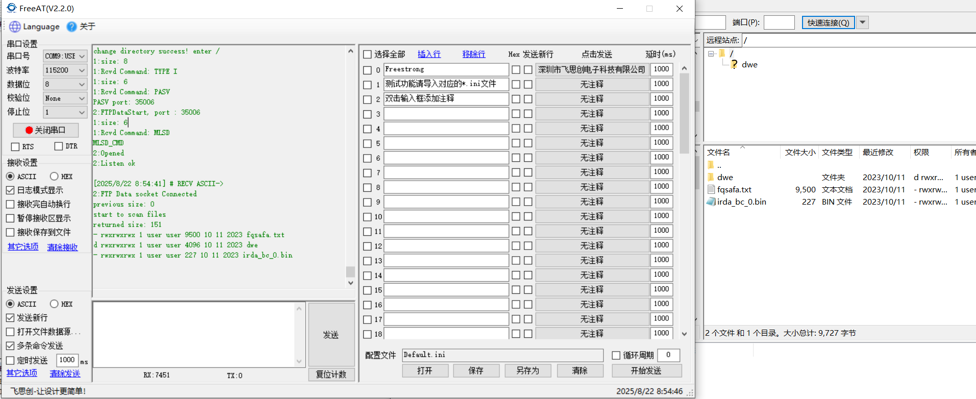
The current FatFs file system supports deleting and uploading files to the server, as well as deleting and uploading directories. The current file system only supports English. To support Chinese, you need to modify the `_CODE_PAGE` macro definition to 936 in `ffconf.h` and use the `cc936.c` file.
Since FatFs does not support access permission functionality, a macro is predefined in the code to set all access permissions to read, write, and execute. On the client side, this will be displayed as `rwxrwxrwx`. Additionally, time modification is currently not supported. If needed, you can access the snp server after powering on the device and enable the RTC clock.
The client uses FileZilla for testing, accessing FileZilla - The free FTP solution for downloading.
Currently, my file system has some files. When accessing the server using FileZilla, the following files will be displayed:
The directory deletion operation is as follows:
Due to the large number of operations, other operations will not be demonstrated. You can test them yourself.
6. Summary
This article details how to implement an FTP server using the W55Mh32Q-EVB, utilizing the FatFs file system for file storage, which can be used to store log information, etc. Thank you for your patience in reading! If you have any questions during the reading process, or would like to learn more about this product and its applications, please feel free to leave a message via private message or in the comments section. We will reply to your message as soon as possible to provide you with more detailed answers and assistance!
————————————————
Copyright Notice: This article is an original article by CSDN blogger "Playing with Ethernet," and is licensed under CC 4.0 BY-SA. Please include the original source link and this statement when reprinting.
Original Link: https://blog.csdn.net/2301_81684513/article/details/150846917