
How to Understand W5500 Driver Flow and Architecture from a Hardware TCP/IP Perspective?
How to Understand W5500 Driver Flow and Architecture from a Hardware TCP/IP Perspective?
How to Understand W5500 Driver Flow and Architecture from a Hardware TCP/IP Perspective?
Summary
This source is a deep technical explainer of the W5500 rather than a board-specific project, but it is highly useful for education because it lays out the W5500’s internal network-stack model, register map, socket state machinery, and memory organization in one place. The platform focus is generic MCU integration over SPI, and the W5500’s role is explicit: it owns the Ethernet transport engine in hardware so the MCU only handles register access, socket commands, and payload movement.
What the Project Does
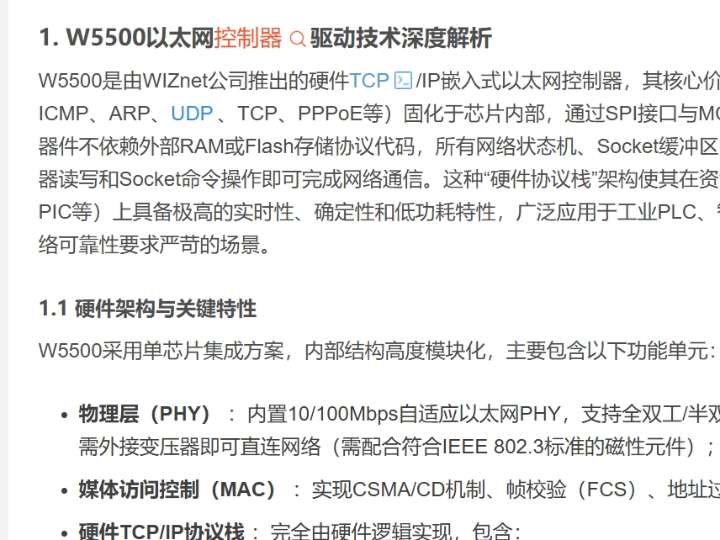
The article is not a complete repository-backed firmware implementation. It is a driver-oriented technical walkthrough of how the W5500 works internally and how an embedded MCU should interact with it. It explains the chip as a hardwired TCP/IP Ethernet controller with integrated MAC, PHY, IPv4, ICMP, ARP, UDP, TCP, and PPPoE support, then moves into register architecture, socket registers, TX/RX memory layout, interrupt behavior, and state-driven communication flow.
From a firmware-flow perspective, the article’s main value is that it makes the W5500 interaction model concrete. The MCU does not run a full software protocol stack here. Instead, it brings up SPI, writes network identity into common registers, configures one of eight sockets, checks status through socket registers, and moves payloads through the chip’s internal SRAM buffers. That is a very different control model from LwIP-style software networking, and it is exactly the kind of separation that is useful in education.
The article is also unusually strong on memory and status flow. It explains that the W5500 exposes three main address domains: common registers, per-socket registers, and TX/RX buffers, all accessed through SPI address mapping. It further explains that send and receive logic depends on registers such as Sn_TX_FSR and Sn_RX_RSR, which means the firmware flow is driven by hardware state, not just by arbitrary API calls. For teaching embedded Ethernet, that is one of the most useful possible viewpoints.
Where WIZnet Fits
The exact WIZnet product here is the W5500. The article describes it as a single-chip hardwired TCP/IP controller with integrated 10/100 Ethernet MAC and PHY, eight concurrent sockets, and internal SRAM-based buffering. It also states that SPI can run up to 80 MHz and that the protocol engine is implemented entirely in hardware, which is the architectural reason the part is attractive on small MCUs.
In this architecture, WIZnet is not just providing a physical Ethernet attachment. The W5500 is the actual network endpoint beneath the application. The MCU sends commands, reads states, and transfers data, but TCP retransmission, checksum handling, ARP behavior, socket state transitions, and much of the packet-handling burden are offloaded into the chip. For firmware education, this distinction matters more than raw feature lists because it explains why a hardware TCP/IP device behaves differently from a software stack.
This also makes the source relevant to both classroom and practical embedded design. A learner can use it to understand how a hardware-offloaded network controller is organized, while a product developer can use the same model to reason about bring-up order, register ownership, socket allocation, and interrupt-driven behavior. That is the core architectural value of the page.
Implementation Notes
This source does use a WIZnet product, but it does not provide a public firmware repository with line-addressable files. It is a technical article, and the implementation evidence is visible as register definitions, memory layout, and driver behavior descriptions rather than a complete application codebase. I am therefore limiting the write-up to what the page explicitly shows.
One of the most important verified details is the common register layout. The article lists key registers such as MR, GAR, SUBR, SHAR, SIPR, IR, IMR, PHYCFGR, and VERSIONR, along with their addresses and purpose. That matters because this is the first step of the firmware flow: before any socket is opened, the MCU must reset the chip, verify chip presence, configure gateway, subnet, MAC, and IP, and confirm PHY link status.
A second important verified detail is the per-socket register model. The article shows socket registers such as Sn_MR, Sn_CR, Sn_IR, Sn_SR, Sn_PORT, Sn_DIPR, Sn_DPORT, Sn_TX_FSR, and Sn_RX_RSR, and explains their role in TCP server, TCP client, UDP, and raw-mode flows. That is the real firmware-flow lesson in the article: socket operation is register-driven, and the host must issue commands in sequence, then poll or interrupt on state changes.
A third important point is the internal memory model. The article explains that TX and RX buffers are mapped into the address space and that their size is allocated per socket. It also states that W5500 uses automatic address increment during SPI buffer access, which is the mechanism that makes payload transfer practical without constant host-side address recalculation. That detail is central to both performance and driver clarity.
The article further states that Sn_CR is a command-trigger register, with operations such as OPEN, LISTEN, CONNECT, and CLOSE, and that Sn_SR and Sn_IR must be used to observe the resulting state transitions. In other words, the firmware flow is not “call a function and forget it.” It is command, wait, inspect state, then continue. That hardware state-machine model is the core of W5500 programming.
Because no MCU-specific source code is given, I am not inventing driver code here. The defensible takeaway is architectural: initialize common registers first, verify PHY and version status, configure socket mode and ports, check free TX space before sending, check pending RX size before receiving, and always treat the socket engine as a stateful hardware subsystem rather than a passive peripheral.
Practical Tips / Pitfalls
- Treat
VERSIONRandPHYCFGRas first-line diagnostics during bring-up. They confirm both chip identity and physical link status before any higher-level debugging makes sense. - Do not send payloads until
Sn_TX_FSRshows enough free space, and do not receive untilSn_RX_RSRshows pending data. The article presents these as the core buffer-control registers. - Learn the difference between common registers, socket registers, and TX/RX memory early. Most beginner confusion comes from mixing these address domains.
- Remember that
Sn_CRis a trigger register, not a persistent mode flag. It launches state-machine actions such as open, listen, connect, and close. - Do not assume hardware offload means zero firmware structure. The chip handles transport behavior, but the host still has to manage configuration order, command sequencing, and interrupt or polling flow.
- Use the article as a driver model reference, not as a complete porting guide. It is strongest on architecture and firmware flow, not on board-specific integration steps.
FAQ
Why is the W5500 useful in embedded network-stack education?
Because it exposes the internal structure of a hardware TCP/IP controller very clearly. Students can learn registers, sockets, TX/RX buffers, interrupts, and network state transitions without first implementing a full software protocol stack on the MCU.
How does the MCU interact with the W5500?
Through SPI-mapped register and memory access. The MCU writes common registers for network identity, configures socket registers for communication roles, and moves payload data through TX/RX buffers while observing status and interrupt registers.
What role does the W5500 play in this source specifically?
It is the subject of the lesson and the hardware network engine being analyzed. The article is essentially a driver and architecture explainer for how firmware should control the W5500.
Can beginners follow this article?
Yes, but it is best for beginner-to-intermediate embedded learners who already understand basic SPI and MCU register access. The article is dense and technical, so it is better as a guided reference than as a first-ever networking tutorial.
How does this compare with a pure software stack such as LwIP?
The architecture is fundamentally different. LwIP keeps the protocol logic in MCU software, while the W5500 moves transport behavior into dedicated hardware and exposes a command-and-register model to the host. That usually reduces MCU burden and increases determinism, though it also means working within the chip’s hardware socket model.
Source
Original article: CSDN post, “W5500以太网控制器驱动技术深度解析,” published in 2026. The visible page presents a detailed architecture and register-level explanation of the W5500, including common registers, socket registers, buffer layout, interrupt model, and hardware TCP/IP behavior.
Tags
W5500, WIZnet, Embedded Ethernet, Hardware TCP/IP, Register Map, Socket Engine, SPI, Buffer Management, Firmware Flow, Education, MCU Networking, Driver Architecture
W5500 드라이버 흐름과 아키텍처를 하드웨어 TCP/IP 관점에서 어떻게 이해할 수 있을까?
Summary
이 자료는 특정 보드 프로젝트라기보다 W5500 자체를 깊이 있게 설명하는 기술 문서에 가깝다. 하지만 교육용으로는 매우 유용하다. W5500의 내부 네트워크 스택 모델, 레지스터 맵, 소켓 상태 기계, 메모리 구성을 한 번에 설명하기 때문이다. 플랫폼 관점에서는 일반적인 MCU의 SPI 연동을 전제로 하며, W5500의 역할은 분명하다. 이 칩이 하드웨어에서 이더넷 전송 엔진을 담당하고, MCU는 레지스터 접근, 소켓 명령, 페이로드 이동만 처리한다.
What the Project Does
이 글은 저장소 기반의 완성형 펌웨어 구현 예제가 아니다. 대신 W5500이 내부적으로 어떻게 동작하고, 임베디드 MCU가 이 칩을 어떻게 다뤄야 하는지를 설명하는 드라이버 중심 기술 해설이다. W5500을 통합 MAC, PHY, IPv4, ICMP, ARP, UDP, TCP, PPPoE 지원을 갖춘 하드와이어드 TCP/IP 이더넷 컨트롤러로 설명한 뒤, 레지스터 구조, 소켓 레지스터, TX/RX 메모리 배치, 인터럽트 동작, 상태 기반 통신 흐름으로 이어진다.
펌웨어 흐름 관점에서 이 글의 가장 큰 가치는 W5500 상호작용 모델을 매우 구체적으로 보여준다는 점이다. 여기서 MCU는 전체 소프트웨어 프로토콜 스택을 실행하지 않는다. 대신 SPI를 초기화하고, 공통 레지스터에 네트워크 정체성을 기록하고, 8개 소켓 중 하나를 설정하고, 소켓 레지스터를 통해 상태를 확인하며, 칩 내부 SRAM 버퍼를 통해 데이터를 주고받는다. 이것은 LwIP 같은 소프트웨어 네트워킹과는 매우 다른 제어 모델이며, 교육용으로 특히 가치가 있다.
또 이 글은 메모리와 상태 흐름 설명이 강하다. W5500은 공통 레지스터, 소켓별 레지스터, TX/RX 버퍼라는 세 가지 주요 주소 영역을 가지며, 모두 SPI 주소 매핑으로 접근된다고 설명한다. 그리고 송수신 로직이 Sn_TX_FSR, Sn_RX_RSR 같은 레지스터에 의존한다고 설명한다. 즉, 펌웨어 흐름은 임의의 API 호출이 아니라 하드웨어 상태에 의해 결정된다. 임베디드 이더넷을 가르치기에 매우 적합한 관점이다.
Where WIZnet Fits
여기서 사용되는 정확한 WIZnet 제품은 W5500이다. 이 글은 W5500을 통합 10/100 Ethernet MAC 및 PHY, 8개의 동시 소켓, 내부 SRAM 버퍼를 가진 단일 칩 하드와이어드 TCP/IP 컨트롤러로 설명한다. 또한 SPI는 최대 80 MHz까지 동작 가능하며, 프로토콜 엔진이 전부 하드웨어에 구현되어 있다고 말한다. 바로 이런 점이 소형 MCU에서 W5500이 매력적인 이유다.
이 아키텍처에서 WIZnet은 단순한 물리 계층 연결만 제공하는 것이 아니다. W5500은 애플리케이션 아래에서 실제 네트워크 엔드포인트 역할을 한다. MCU는 명령을 보내고, 상태를 읽고, 데이터를 옮기지만, TCP 재전송, 체크섬 처리, ARP 동작, 소켓 상태 전이, 그리고 상당한 패킷 처리 부담은 칩 내부로 오프로딩된다. 교육 관점에서는 이 차이가 매우 중요하다. 하드웨어 TCP/IP 디바이스가 왜 소프트웨어 스택과 다르게 동작하는지 이해할 수 있기 때문이다.
이 점 때문에 이 자료는 교육과 실무 모두에 의미가 있다. 학습자는 하드웨어 오프로딩 네트워크 컨트롤러의 구조를 배울 수 있고, 제품 개발자는 같은 모델을 이용해 구동 순서, 레지스터 역할, 소켓 할당, 인터럽트 기반 동작을 설계할 수 있다. 이것이 이 페이지의 핵심 아키텍처 가치다.
Implementation Notes
이 자료는 실제로 WIZnet 제품을 다루지만, 공개 저장소나 줄 단위 파일 경로를 제공하지는 않는다. 구현 근거는 보이는 레지스터 정의, 메모리 구조, 드라이버 동작 설명이며, 완전한 애플리케이션 코드베이스는 아니다. 따라서 아래 설명은 글에서 명시적으로 보이는 내용만 기준으로 한다.
가장 중요한 검증 가능한 내용 중 하나는 공통 레지스터 구조다. 글은 MR, GAR, SUBR, SHAR, SIPR, IR, IMR, PHYCFGR, VERSIONR 같은 핵심 레지스터와 그 주소 및 역할을 나열한다. 이것이 중요한 이유는, 펌웨어 흐름의 첫 단계가 바로 여기에 있기 때문이다. 소켓을 열기 전에 MCU는 칩을 리셋하고, 칩이 맞는지 확인하고, 게이트웨이, 서브넷, MAC, IP를 설정하고, PHY 링크 상태를 확인해야 한다.
두 번째로 중요한 내용은 소켓별 레지스터 모델이다. 글은 Sn_MR, Sn_CR, Sn_IR, Sn_SR, Sn_PORT, Sn_DIPR, Sn_DPORT, Sn_TX_FSR, Sn_RX_RSR 같은 소켓 레지스터를 보여주며, 이것들이 TCP 서버, TCP 클라이언트, UDP, RAW 모드 흐름에서 어떤 역할을 하는지 설명한다. 이것이 바로 이 글의 핵심 펌웨어 교훈이다. 소켓 동작은 레지스터 기반이며, 호스트는 순서대로 명령을 내리고, 그 뒤 폴링이나 인터럽트로 상태 변화를 확인해야 한다.
세 번째로 중요한 점은 내부 메모리 모델이다. 글은 TX와 RX 버퍼가 주소 공간 안에 매핑되어 있고, 그 크기가 소켓별로 할당된다고 설명한다. 또한 SPI 버퍼 접근 시 자동 주소 증가가 이루어진다고 말한다. 이것이 중요한 이유는, 이 기능 덕분에 호스트가 매 바이트마다 주소를 다시 계산하지 않아도 되어 실제 페이로드 전송이 실용적으로 가능해지기 때문이다.
또한 글은 Sn_CR이 명령 트리거 레지스터이며, OPEN, LISTEN, CONNECT, CLOSE 같은 동작을 수행한다고 설명한다. 그리고 결과 상태는 Sn_SR과 Sn_IR로 반드시 확인해야 한다고 말한다. 즉, 펌웨어 흐름은 “함수 한번 호출하고 끝”이 아니다. 명령을 내리고, 기다리고, 상태를 읽고, 그다음 단계로 넘어가는 구조다. 이 하드웨어 상태 기계 모델이 W5500 프로그래밍의 핵심이다.
MCU별 소스 코드는 제공되지 않으므로, 여기서 임의의 드라이버 코드를 만들지는 않는다. 이 자료에서 얻을 수 있는 가장 정확한 결론은 다음과 같다. 먼저 공통 레지스터를 초기화하고, PHY와 버전 상태를 확인하고, 소켓 모드와 포트를 설정하고, 송신 전에는 Sn_TX_FSR로 남은 공간을 확인하고, 수신 전에는 Sn_RX_RSR로 대기 중인 데이터를 확인해야 한다. 그리고 소켓 엔진은 단순 주변장치가 아니라 상태를 가진 하드웨어 서브시스템으로 다뤄야 한다.
Practical Tips / Pitfalls
- 구동 초기에
VERSIONR와PHYCFGR를 가장 먼저 확인하는 편이 좋다. 칩 식별과 물리 링크 상태를 동시에 확인할 수 있기 때문이다. Sn_TX_FSR가 충분한 빈 공간을 보여주기 전에는 송신하지 않는 편이 좋고,Sn_RX_RSR가 대기 중 데이터를 보여주기 전에는 수신을 시도하지 않는 편이 좋다.- 공통 레지스터, 소켓 레지스터, TX/RX 메모리의 차이를 초기에 확실히 구분하는 것이 좋다. 초보자가 가장 많이 헷갈리는 부분이 바로 이 주소 영역 구분이다.
Sn_CR은 지속적인 모드 플래그가 아니라 트리거 레지스터라는 점을 기억해야 한다. open, listen, connect, close 같은 상태 기계 동작을 시작시키는 역할이다.- 하드웨어 오프로딩이 있다고 해서 펌웨어 구조가 필요 없는 것은 아니다. 칩이 전송 동작을 맡더라도, 호스트는 설정 순서, 명령 시퀀스, 인터럽트 또는 폴링 흐름을 여전히 관리해야 한다.
- 이 글은 드라이버 모델 참고 자료로는 좋지만, 완전한 포팅 가이드로 보기에는 부족하다. 보드별 통합 절차보다는 아키텍처와 펌웨어 흐름 설명에 더 강하다.
FAQ
왜 W5500이 임베디드 네트워크 스택 교육에 유용한가?
하드웨어 TCP/IP 컨트롤러의 내부 구조를 매우 분명하게 보여주기 때문이다. 학생은 전체 소프트웨어 프로토콜 스택을 MCU에 구현하지 않고도 레지스터, 소켓, TX/RX 버퍼, 인터럽트, 네트워크 상태 전이를 배울 수 있다.
MCU는 W5500과 어떻게 상호작용하는가?
SPI로 매핑된 레지스터 및 메모리 접근을 통해 상호작용한다. MCU는 공통 레지스터에 네트워크 정체성을 기록하고, 소켓 레지스터로 통신 역할을 설정하고, TX/RX 버퍼를 통해 데이터를 옮기면서 상태 및 인터럽트 레지스터를 확인한다.
이 자료에서 W5500의 구체적인 역할은 무엇인가?
이 자료의 핵심 주제이자, 펌웨어가 제어해야 하는 하드웨어 네트워크 엔진 그 자체다. 글 전체가 사실상 W5500을 어떤 드라이버 모델과 아키텍처로 제어해야 하는지 설명하는 자료다.
초보자도 이 글을 따라갈 수 있는가?
가능하다. 다만 기본적인 SPI와 MCU 레지스터 접근을 알고 있는 초급~중급 임베디드 학습자에게 더 적합하다. 내용이 기술적으로 밀도가 높기 때문에, 완전 초보자에게는 첫 네트워킹 입문서보다는 참고서에 가깝다.
LwIP 같은 순수 소프트웨어 스택과 비교하면 어떤 차이가 있는가?
아키텍처가 근본적으로 다르다. LwIP는 프로토콜 로직을 MCU 소프트웨어 안에 두지만, W5500은 전송 동작을 전용 하드웨어로 넘기고, 호스트에는 명령과 레지스터 중심 제어 모델을 제공한다. 이 방식은 MCU 부담을 줄이고 결정성을 높이는 대신, 칩의 하드웨어 소켓 모델 안에서 동작해야 한다는 특징이 있다.