



How to Teach Ethernet Hardware Wiring with WIZnet W5500 on MCU Education Boards?
This education-focused hardware article explains how to teach wired Ethernet design with WIZnet W5500 on MCU education boards using an external-transformer refe
How to Teach Ethernet Hardware Wiring with WIZnet W5500 on MCU Education Boards?
Summary
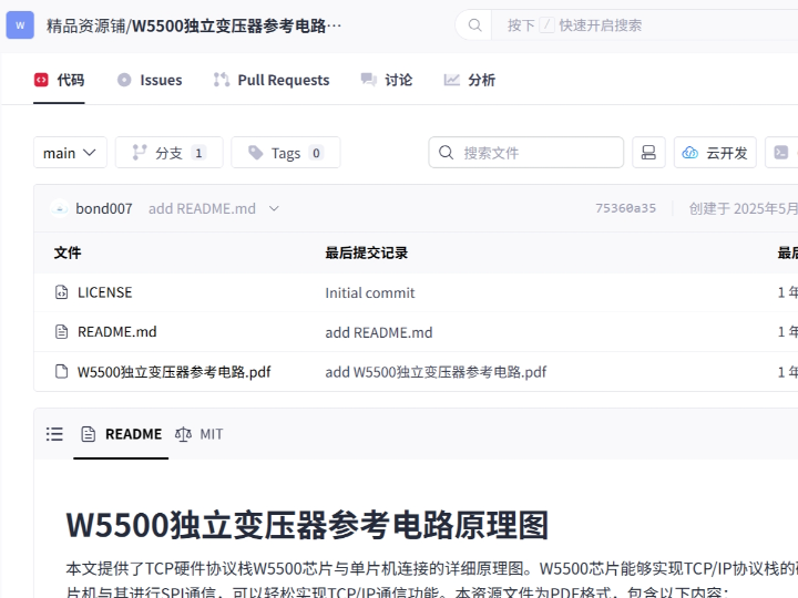
This education-focused hardware article explains how to teach wired Ethernet design with WIZnet W5500 on MCU education boards using an external-transformer reference circuit. The GitCode project is a W5500 independent-transformer schematic resource: it describes a W5500-to-MCU SPI connection and an Ethernet output stage that uses a separate transformer instead of being limited to a common RJ45 connector with integrated magnetics. W5500 provides the Ethernet MAC/PHY, hardwired TCP/IP stack, socket engine, and packet buffering, while the MCU board provides SPI control, reset handling, interrupt handling, and application firmware.
What the Project Does
The project is a hardware reference for building or teaching a W5500 Ethernet interface. It is not a complete firmware project or a robot/application demo. Its purpose is to show how W5500 connects to an MCU and how the Ethernet physical interface can be built with an independent transformer. The GitCode README states that the schematic shows W5500 connected to a microcontroller through SPI and that the independent transformer makes the output interface more flexible than a standard RJ45 jack-only design.
For an education board, the practical signal flow is:
MCU firmware → SPI bus and control pins → W5500 → TX/RX differential pairs → external transformer → Ethernet connector or custom output interface → switch, router, PC, or lab network.
This is useful in a classroom because students can see that Ethernet is not only a software socket API. The design includes MCU-side digital wiring, reset and interrupt control, clocking, power domains, PHY configuration pins, differential MDI routing, magnetics, connector choices, EMI constraints, and link/activity indication. A related CSDN mirror says the resource is a PDF containing the W5500-to-MCU net circuit, W5500 output-interface design, and independent-transformer usage.
Where WIZnet Fits
The exact WIZnet product is W5500. It sits between the MCU and the Ethernet physical interface. On the MCU side, W5500 exposes SPI signals such as SCLK, MOSI, MISO, and SCSn, plus reset and interrupt signals such as RSTn and INTn. On the Ethernet side, it exposes differential PHY signals such as TXP, TXN, RXP, and RXN, which are routed through the magnetic interface before reaching the cable connector. The official WIZnet external-transformer schematic shows these same MCU-side and Ethernet-side signal groups around the W5500.
W5500 is a hardwired TCP/IP Internet controller with SPI access up to 80 MHz. It integrates a 10/100 Ethernet MAC and PHY, supports TCP, UDP, ICMP, IPv4, ARP, IGMP, and PPPoE, provides 8 independent sockets, and includes 32 KB internal Tx/Rx buffer memory.
For education, W5500 is useful because it makes the boundary between hardware and network software visible. The MCU does not need to implement a full TCP/IP stack. Instead, students can learn hardware bring-up first: power, reset, SPI, crystal, PHY configuration, transformer wiring, link LEDs, and EMI layout. After that, firmware can configure IP addressing and sockets.
Implementation Notes
The GitCode project confirms a W5500 independent-transformer schematic resource, but the PDF contents were not exposed as directly inspectable source files through the repository page. Therefore, no project-specific firmware code is quoted here. The implementation notes below are hardware-level and use the GitCode description, related CSDN mirror, and WIZnet’s official external-transformer reference schematic.
Hardware block: MCU-to-W5500 digital interface
What it configures: SPI and control wiring.
Why it matters: students should verify the digital control path before expecting Ethernet link or TCP/UDP communication.
The MCU-side wiring should include SCLK, MOSI, MISO, SCSn, RSTn, INTn, 3.3 V power, and ground. RSTn should be connected to an MCU GPIO so firmware can recover the Ethernet controller without power-cycling the full board. INTn is optional for a first lab, but it is useful when teaching receive events, disconnect events, timeouts, and socket-state transitions. WIZnet’s official external-transformer schematic shows SCLK, MISO, MOSI, SCSn, RSTn, and INTn as the host-side control signals.
Hardware block: W5500 PHY and independent transformer output
What it configures: Ethernet analog-side connection.
Why it matters: this is the part students often miss when they treat W5500 as only an SPI device.
The W5500 PHY side routes TXP, TXN, RXP, and RXN through the magnetic interface. The official WIZnet external-transformer schematic shows a discrete transformer stage between the W5500 differential pairs and the connector-side pins, along with termination, capacitors, common grounding, and LED connections. It also shows a 25 MHz crystal circuit for W5500 clocking.
Hardware block: EMI and layout constraints
What it configures: practical Ethernet layout behavior.
Why it matters: a schematic can be electrically correct but still unreliable if the layout is poor.
WIZnet’s external-transformer reference schematic includes EMI guidance: damping resistors may be applied, power jacks should not be placed near the RJ45 connector, power and ground planes should be voided under discrete magnetic components, MDI differential traces should be equal length, the power source should be stable, CAT5E cable should be used, and a ferrite bead can be used between digital and analog VDD.
Practical Tips / Pitfalls
- Start the lab with power, reset, and SPI continuity before connecting to a network.
- Keep
SCLK,MOSI,MISO, andSCSnshort and clean on prototype boards. - Route
RSTnandINTnto the MCU instead of leaving them as afterthoughts. - Treat
TXP/TXNandRXP/RXNas differential Ethernet signals, not ordinary GPIO traces. - Keep the transformer and connector area clear of noisy power-entry components.
- Use the link/activity LEDs as lab diagnostics before testing TCP or UDP.
- Teach students to separate digital faults, PHY faults, IP configuration faults, and socket faults.
FAQ
Q: Why use WIZnet W5500 for Ethernet hardware education?
A: W5500 exposes both sides of embedded Ethernet design. Students can wire an MCU-facing SPI interface and also study the PHY-side transformer, differential pairs, clock, reset, interrupt, LEDs, power filtering, and EMI layout. At the same time, W5500 provides hardwired TCP/IP, 8 sockets, and 32 KB internal buffering, so the software side remains manageable for a teaching board.
Q: How does W5500 connect to the MCU education board?
A: W5500 connects through SPI using SCLK, MOSI, MISO, and SCSn, with RSTn for reset and INTn for interrupt-driven events. The official external-transformer schematic shows these host-side signals connected to the W5500 package, while the GitCode project description states that W5500 connects to the microcontroller through SPI.
Q: What role does W5500 play in this project?
A: W5500 is the Ethernet controller and teaching target. It bridges MCU firmware to the physical Ethernet interface: SPI and control pins on one side, hardwired TCP/IP and socket behavior internally, and 10/100 Ethernet PHY signals through the transformer on the other side.
Q: Can beginners follow this hardware project?
A: Yes, if the lesson is staged. Start with the W5500 pin groups, then SPI wiring, reset, interrupt, 25 MHz clock, power decoupling, PHY differential pairs, transformer output, LEDs, and finally basic IP/socket firmware. The schematic is useful precisely because it shows hardware details that beginner Ethernet modules normally hide.
Q: How is this different from using an RJ45 connector with integrated magnetics?
A: An integrated-magjack design is simpler for module-style products because the transformer is inside the connector. The independent-transformer approach separates the magnetics from the output connector, which makes the physical interface more flexible and exposes more of the Ethernet analog front end for teaching. WIZnet provides both external-transformer and RJ45-with-magnetics reference schematics, so students can compare the two hardware styles directly.
Source
Original source: GitCode repository “W5500独立变压器参考电路原理图”. The page describes a W5500 independent-transformer schematic project, W5500-to-MCU SPI connection, flexible output-interface design, and MIT license.
Related CSDN mirror: “W5500独立变压器参考电路原理图”, which describes the resource as a PDF containing the W5500-to-MCU net circuit, W5500 output-interface design, and independent-transformer usage. The article states CC 4.0 BY-SA.
WIZnet product reference: W5500 documentation and feature list, including hardwired TCP/IP, SPI, 8 sockets, 32 KB buffer memory, and official hardware-reference schematic links.
WIZnet hardware reference: official W5500-Ref-ExternalMag schematic and W5500-Ref-RJ45WithMag schematic.
Tags
#W5500 #WIZnet #Education #Ethernet #HardwareWiring #SPI #Transformer #RJ45 #PHY #Schematic #MCU #NetworkStack
MCU 교육 보드에서 WIZnet W5500으로 Ethernet 하드웨어 배선을 가르치는 방법은?
요약
이 교육 중심 하드웨어 글은 WIZnet W5500을 사용해 MCU 교육 보드에서 외부 transformer 기반 유선 Ethernet 설계를 가르치는 방법을 설명합니다. GitCode 프로젝트는 W5500 independent-transformer schematic resource입니다. 이 자료는 W5500과 MCU의 SPI 연결, 그리고 일반적인 integrated magnetics RJ45 connector에만 의존하지 않는 독립 transformer 기반 Ethernet output stage를 설명합니다. W5500은 Ethernet MAC/PHY, hardwired TCP/IP stack, socket engine, packet buffering을 제공하고, MCU 보드는 SPI control, reset handling, interrupt handling, application firmware를 담당합니다.
프로젝트가 하는 일
이 프로젝트는 W5500 Ethernet interface를 제작하거나 교육하기 위한 hardware reference입니다. 완성된 firmware project나 robot/application demo가 아닙니다. 목적은 W5500이 MCU에 어떻게 연결되는지, 그리고 Ethernet physical interface를 independent transformer로 어떻게 구성할 수 있는지 보여주는 것입니다. GitCode README는 schematic이 W5500과 microcontroller를 SPI로 연결하는 구조를 보여주며, independent transformer를 사용하면 standard RJ45 jack-only design보다 output interface가 더 유연해진다고 설명합니다.
교육 보드에서 실제 signal flow는 다음과 같습니다.
MCU firmware → SPI bus and control pins → W5500 → TX/RX differential pairs → external transformer → Ethernet connector 또는 custom output interface → switch, router, PC 또는 lab network
이 구조는 classroom에서 유용합니다. 학생들이 Ethernet을 단순한 software socket API로만 보지 않게 해주기 때문입니다. 설계에는 MCU-side digital wiring, reset 및 interrupt control, clocking, power domain, PHY configuration pin, differential MDI routing, magnetics, connector choice, EMI constraint, link/activity indication이 포함됩니다. 관련 CSDN mirror는 이 resource가 W5500-to-MCU net circuit, W5500 output-interface design, independent-transformer usage를 포함한 PDF라고 설명합니다.
WIZnet이 들어가는 위치
이 프로젝트에서 사용되는 정확한 WIZnet 제품은 W5500입니다. W5500은 MCU와 Ethernet physical interface 사이에 위치합니다. MCU 측에서는 SCLK, MOSI, MISO, SCSn 같은 SPI signal과 RSTn, INTn 같은 reset 및 interrupt signal을 제공합니다. Ethernet 측에서는 TXP, TXN, RXP, RXN 같은 differential PHY signal을 제공하며, 이 신호들은 cable connector에 도달하기 전에 magnetic interface를 통과합니다. WIZnet 공식 external-transformer schematic도 W5500 주변에 같은 MCU-side 및 Ethernet-side signal group을 보여줍니다.
W5500은 최대 80 MHz SPI access를 지원하는 hardwired TCP/IP Internet controller입니다. 10/100 Ethernet MAC and PHY를 통합하고, TCP, UDP, ICMP, IPv4, ARP, IGMP, PPPoE를 지원하며, 8개 independent socket과 32 KB internal Tx/Rx buffer memory를 포함합니다.
교육용으로 W5500이 유용한 이유는 hardware와 network software 사이의 경계를 명확하게 보여주기 때문입니다. MCU는 full TCP/IP stack을 구현할 필요가 없습니다. 대신 학생들은 먼저 hardware bring-up을 학습할 수 있습니다. 여기에는 power, reset, SPI, crystal, PHY configuration, transformer wiring, link LED, EMI layout이 포함됩니다. 그다음 firmware에서 IP addressing과 socket을 설정할 수 있습니다.
구현 참고 사항
GitCode 프로젝트는 W5500 independent-transformer schematic resource임을 확인할 수 있지만, repository page를 통해 PDF 내용을 직접 inspect 가능한 source file 형태로 확인할 수는 없었습니다. 따라서 여기서는 프로젝트별 firmware code를 인용하지 않습니다. 아래 구현 참고 사항은 GitCode 설명, 관련 CSDN mirror, WIZnet 공식 external-transformer reference schematic을 기반으로 한 hardware-level 설명입니다.
Hardware block: MCU-to-W5500 digital interface
설정 내용: SPI 및 control wiring
중요한 이유: 학생들은 Ethernet link나 TCP/UDP 통신을 기대하기 전에 digital control path를 먼저 검증해야 합니다.
MCU-side wiring에는 SCLK, MOSI, MISO, SCSn, RSTn, INTn, 3.3 V power, ground가 포함되어야 합니다. RSTn은 MCU GPIO에 연결하는 것이 좋습니다. 그래야 firmware가 전체 보드를 power-cycle하지 않고 Ethernet controller를 복구할 수 있습니다. INTn은 첫 lab에서는 선택 사항일 수 있지만, receive event, disconnect event, timeout, socket-state transition을 가르칠 때 유용합니다. WIZnet 공식 external-transformer schematic은 SCLK, MISO, MOSI, SCSn, RSTn, INTn을 host-side control signal로 보여줍니다.
Hardware block: W5500 PHY and independent transformer output
설정 내용: Ethernet analog-side connection
중요한 이유: 학생들이 W5500을 단순한 SPI device로만 취급할 때 가장 자주 놓치는 부분입니다.
W5500 PHY 측에서는 TXP, TXN, RXP, RXN이 magnetic interface를 통해 routing됩니다. WIZnet 공식 external-transformer schematic은 W5500 differential pair와 connector-side pin 사이의 discrete transformer stage, termination, capacitor, common grounding, LED connection을 보여줍니다. 또한 W5500 clocking을 위한 25 MHz crystal circuit도 포함합니다.
Hardware block: EMI and layout constraints
설정 내용: 실제 Ethernet layout behavior
중요한 이유: schematic이 전기적으로 맞더라도 layout이 나쁘면 안정적으로 동작하지 않을 수 있습니다.
WIZnet external-transformer reference schematic은 EMI 관련 guidance를 포함합니다. Damping resistor를 적용할 수 있고, power jack은 RJ45 connector 근처에 배치하지 않는 것이 좋으며, discrete magnetic component 아래에는 power 및 ground plane을 비우고, MDI differential trace는 equal length로 맞춰야 합니다. 또한 안정적인 power source, CAT5E cable 사용, digital VDD와 analog VDD 사이의 ferrite bead 사용도 제안됩니다.
실무 팁 / 주의점
- Network에 연결하기 전에 power, reset, SPI continuity부터 lab을 시작해야 합니다.
- Prototype board에서는
SCLK,MOSI,MISO,SCSn을 짧고 깨끗하게 유지해야 합니다. RSTn과INTn은 나중에 생각할 pin이 아니라 MCU에 라우팅해야 하는 control signal로 다뤄야 합니다.TXP/TXN과RXP/RXN은 일반 GPIO trace가 아니라 differential Ethernet signal로 취급해야 합니다.- Transformer와 connector 영역은 noisy power-entry component에서 떨어뜨려야 합니다.
- TCP 또는 UDP를 테스트하기 전에 link/activity LED를 lab diagnostic으로 활용해야 합니다.
- 학생들에게 digital fault, PHY fault, IP configuration fault, socket fault를 구분하도록 가르쳐야 합니다.
FAQ
Q: Ethernet hardware 교육에 왜 WIZnet W5500을 사용하나요?
A: W5500은 embedded Ethernet design의 양쪽을 모두 보여줍니다. 학생들은 MCU-facing SPI interface를 배선하면서 동시에 PHY-side transformer, differential pair, clock, reset, interrupt, LED, power filtering, EMI layout을 학습할 수 있습니다. 동시에 W5500은 hardwired TCP/IP, 8개 socket, 32 KB internal buffering을 제공하므로 teaching board의 software side가 지나치게 복잡해지지 않습니다.
Q: W5500은 MCU 교육 보드에 어떻게 연결되나요?
A: W5500은 SCLK, MOSI, MISO, SCSn을 사용하는 SPI로 연결되고, reset용 RSTn, interrupt-driven event용 INTn을 함께 사용합니다. 공식 external-transformer schematic은 이러한 host-side signal이 W5500 package에 연결되는 구조를 보여주며, GitCode project description도 W5500이 microcontroller에 SPI로 연결된다고 설명합니다.
Q: 이 프로젝트에서 W5500은 어떤 역할을 하나요?
A: W5500은 Ethernet controller이자 teaching target입니다. 한쪽에서는 SPI 및 control pin으로 MCU firmware와 연결되고, 내부에서는 hardwired TCP/IP와 socket behavior를 제공하며, 다른 쪽에서는 transformer를 통해 10/100 Ethernet PHY signal을 제공합니다.
Q: 초보자도 이 hardware project를 따라갈 수 있나요?
A: 가능합니다. 다만 수업을 단계적으로 구성해야 합니다. W5500 pin group부터 시작해 SPI wiring, reset, interrupt, 25 MHz clock, power decoupling, PHY differential pair, transformer output, LED, 기본 IP/socket firmware 순서로 진행하는 것이 좋습니다. 이 schematic이 유용한 이유는 beginner Ethernet module이 보통 숨기는 hardware detail을 보여주기 때문입니다.
Q: Integrated magnetics RJ45 connector를 사용하는 것과 무엇이 다른가요?
A: Integrated-magjack design은 transformer가 connector 안에 들어 있으므로 module-style product에는 더 단순합니다. Independent-transformer approach는 magnetics와 output connector를 분리하므로 physical interface가 더 유연해지고, Ethernet analog front end를 교육용으로 더 잘 보여줄 수 있습니다. WIZnet은 external-transformer reference schematic과 RJ45-with-magnetics reference schematic을 모두 제공하므로, 학생들은 두 hardware style을 직접 비교할 수 있습니다.
출처
Original source: GitCode repository “W5500独立变压器参考电路原理图”. 해당 page는 W5500 independent-transformer schematic project, W5500-to-MCU SPI connection, flexible output-interface design, MIT license를 설명합니다.
https://gitcode.com/Premium-Resources/684e3
Related CSDN mirror: “W5500独立变压器参考电路原理图”, W5500-to-MCU net circuit, W5500 output-interface design, independent-transformer usage를 포함한 PDF resource라고 설명합니다. 해당 article은 CC 4.0 BY-SA를 명시합니다.
https://blog.csdn.net/gitblog_06701/article/details/147823300
WIZnet product reference: W5500 documentation and feature list, including hardwired TCP/IP, SPI, 8 sockets, 32 KB buffer memory, and official hardware-reference schematic links.
https://docs.wiznet.io/Product/Chip/Ethernet/W5500
WIZnet hardware reference: official W5500-Ref-ExternalMag schematic and W5500-Ref-RJ45WithMag schematic.
https://docs.wiznet.io/assets/files/w5500_sch_v110_use_trans_-18b3297138bdf20fafd0f95e4c19358d.pdf
태그
#W5500 #WIZnet #Education #Ethernet #HardwareWiring #SPI #Transformer #RJ45 #PHY #Schematic #MCU #NetworkStack