
Build an Ethernet-Powered IoT Camera with HTTP / MQTT
W6300-EVB-PICO2 board streaming OV2640 camera images to Adafruit IO for real-time web dashboard viewing.
Introduction
Modern IoT applications require reliable, real-time image streaming capabilities for applications ranging from security surveillance to remote monitoring. While WiFi-based solutions are common, they often suffer from signal instability and limited range. This project demonstrates how to build a robust Ethernet-powered camera system using the W6300-EVB-PICO2 microcontroller with built-in Ethernet capabilities, streaming live images to Adafruit IO using both HTTP and MQTT protocols for maximum flexibility and reliability.
Step 1: Gather Components
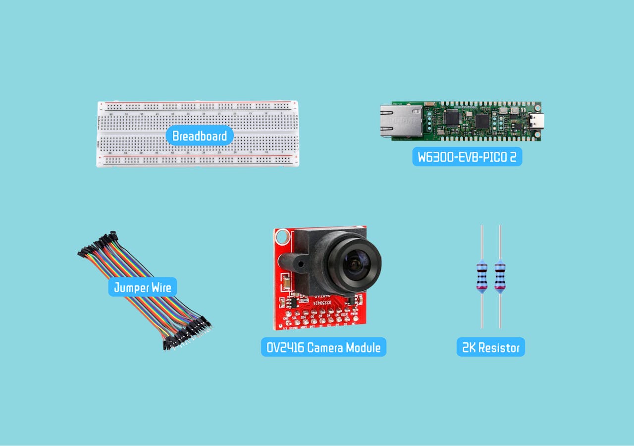
For this project, you will need:
- W6300-EVB-PICO2 Microcontroller
- OV2640 Camera Module
- Resistor 2K ohm
- Breadboard and jumper wires
Step 2: Hardware Setup
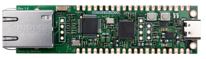
W6300-EVB-PICO2 - Advanced IoT Foundation
The W6300-EVB-PICO2 provides an excellent foundation for this project:
- RP2350 dual Cortex-M33 (150MHz) + 520KB SRAM for processing images
- 16MB flash memory + 64KB network buffers for data handling
- 8 simultaneous sockets for HTTP/MQTT communications
- IPv4/IPv6 dual stack support for future-proof networking
- Enhanced security with TrustZone + secure boot
ConnectionsOV2640 Camera → W6300-EVB-PICO2
- VSYNC → GP12
- HREF → GP11
- PCLK → GP10
- D0-D7 → GP0-GP7 (data bus)
- SCL → GP9 (I2C clock) → WITH pull-up resistorto 3.3V
- SDA → GP8 (I2C data) → WITH pull-up resistorto 3.3V
- RESET → GP13 (optional)
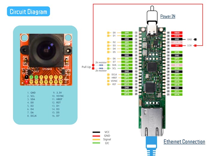
Important: Double-check all connections for security and accuracy before powering on the board.
Why Pull-up Resistors Are Essential?
- I2C Protocol Requirement: I2C is an open-drain/open-collector bus that requires pull-ups
- Signal Integrity: Without pull-ups, SDA and SCL lines will float, causing communication errors
- Proper Logic Levels: Pull-ups ensure signals reach proper HIGH (3.3V) and LOW (0V) levels
- Camera Detection: The camera's I2C address (0x30) won't be detected without pull-ups
Resistor Specifications
- Value: 4.7kΩ (4700 ohms) is standard, but 2kΩ-10kΩ works
- Power: 1/4 watt (0.25W) standard resistors
- Quantity: 2 resistors (one for SDA, one for SCL)
- Connection: Between 3.3V and each I2C line
Step 3: Setting Up Adafruit IO
Setting Up Adafruit IO
Create Feeds:
- Camera feed
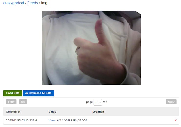
Design Dashboard:
- Go to the Dashboard section to design the interface, adding the image block

Step 4: Code Explanation
Import Required Libraries
Core System Libraries
time- Provides timing functions for delays and intervals between image capturesboard- Accesses microcontroller-specific pin definitions and hardware featuresbusio- Handles serial communication protocols including I2C for camera control and SPI for Ethernet communicationdigitalio- Manages GPIO pins for camera control signals and Ethernet reset functions
Camera Control
adafruit_ov2640- Dedicated library for OV2640 camera module control, providing functions for image capture, resolution settings, and JPEG compression configuration
Ethernet Connectivity (W6300 Specific)
wiznet- WIZnet chipset drivers enabling Ethernet connectivity on the W6300-EVB-PICO2adafruit_wiznet5k- High-level Ethernet interface library with WIZNET5K class for network initialization and managementsocketpool- Creates and manages network sockets for both HTTP and MQTT communications
Data Processing & Encoding
binascii- Converts binary image data to ASCII formats suitable for network transmissionssl- Provides secure socket layer support for encrypted communications (though often disabled for performance)gc- Garbage collection module for memory management, crucial when handling large image buffers
Cloud Communication Protocols
adafruit_requests- Simplified HTTP client for making REST API calls to Adafruit IOadafruit_minimqtt- Lightweight MQTT client for publish/subscribe messaging with Adafruit IOadafruit_io- Adafruit IO integration library with IO_HTTP class for HTTP-based data transmission
import time
import board
import busio
import adafruit_ov2640
import wiznet
import digitalio
import binascii
import gc
import ssl
from adafruit_wiznet5k.adafruit_wiznet5k import WIZNET5K
import adafruit_wiznet5k.adafruit_wiznet5k_socketpool as socketpool

# MQTT
import adafruit_minimqtt.adafruit_minimqtt as MQTT

#HTTP
from adafruit_io.adafruit_io import IO_HTTP
import adafruit_requests

try:
    from secrets import secrets
except ImportError:
    print("MQTT secrets are kept in secrets.py, please add them there!")
    raise
Secrets Management
This dictionary stores your Adafruit IO credentials. You should create a separate secrets.py file to keep sensitive information secure.
secrets = {
"aio_username": "YOUR_ADAFRUIT_IO_USERNAME",
"aio_key": "YOUR_ADAFRUIT_IO_KEY"
}
Network Configuration
Defines the MAC address, static IP address, subnet mask, gateway, and DNS server addresses for network connectivity.
MY_MAC = "00:01:02:03:04:05"
IP_ADDRESS = (192, 168, 1, 100)  # Static IP configuration
SUBNET_MASK = (255, 255, 255, 0)
GATEWAY_ADDRESS = (192, 168, 1, 1)
DNS_SERVER = (8, 8, 8, 8)
Hardware Initialization
- Ethernet Configurations: Configures pins for Ethernet connectivity and resets the WIZnet module.
- Initialize Ethernet: The WIZnet module is initialized using SPI, with DHCP enabled to get an IP address auomatically.
# Ethernet reset pin
ethernetRst = digitalio.DigitalInOut(board.W5K_RST)
ethernetRst.direction = digitalio.Direction.OUTPUT

# SPI configuration for Ethernet
cs = digitalio.DigitalInOut(board.W5K_CS)
spi_bus = wiznet.PIO_SPI(board.W5K_SCK,
                     quad_io0=board.W5K_MOSI,
                     quad_io1=board.W5K_MISO,
                     quad_io2=board.W5K_IO2,
                     quad_io3=board.W5K_IO3)

# Reset W5x00
ethernetRst.value = False
time.sleep(1)
ethernetRst.value = True

# Initialize Ethernet
eth = WIZNET5K(spi_bus, cs, is_dhcp=True, mac=MY_MAC, debug=False)

# Create socket pool - Manages network connections for libraries
pool = socketpool.SocketPool(eth)
Camera Setup
Initializes I2C communication for camera control and configures the OV2640 camera module with parallel data transfer pins.
Details:
- I2C pins (GP8, GP9) are used for camera configuration and settings
- Parallel data pins (GP0-GP7) handle high-speed image data transfer using 8-bit parallel interface
- Control signals (clock, vsync, href, reset) manage timing and synchronization of image capture:
- Clock (GP10): Pixel clock for data synchronization
- VSYNC (GP12): Vertical sync signal indicating frame start
- HREF (GP11): Horizontal reference signal for row data
- Reset (GP13): Hardware reset control for the camera module
# Initialize I2C communication for camera control
i2c = busio.I2C(board.GP9, board.GP8)

# Configure OV2640 camera with all required pins
cam = adafruit_ov2640.OV2640(
    i2c,
    data_pins=[board.GP0, board.GP1, board.GP2, board.GP3,
              board.GP4, board.GP5, board.GP6, board.GP7],
    clock=board.GP10,
    vsync=board.GP12,
    href=board.GP11,
    reset=board.GP13,
)

# Set image resolution and format
cam.size = adafruit_ov2640.OV2640_SIZE_VGA
cam.colorspace = adafruit_ov2640.OV2640_COLOR_JPEG

# Camera initialization delay
time.sleep(2)
Communication Protocol Selection
Allows the user to choose between HTTP or MQTT protocols for data transmission to Adafruit IO.
Process:
- User input prompts selection of communication protocol
- Based on selection, initializes appropriate client (HTTP or MQTT)
- Sets up connection parameters for Adafruit IO platform
- Provides status feedback on connection readiness
HTTP Mode:
- Uses SSL-secured HTTP sessions for data transfer
- Creates HTTP IO client for Adafruit IO communication
- Suitable for simpler request/response data transmission
MQTT Mode:
- Establishes persistent MQTT connection for publish/subscribe communication
- Connects to Adafruit IO's MQTT broker
- Uses unencrypted connection (SSL disabled for memory efficiency)
- Creates topic path for image feed publishing
Mode = input("HTTP or MQTT? ").strip().upper()
# Initialize client based on mode
if Mode == "HTTP":
ssl_context = ssl.create_default_context()
requests = adafruit_requests.Session(pool, ssl_context)
http_io = IO_HTTP(aio_username, aio_key, requests)
print("HTTP ready")
elif Mode == "MQTT":
mqtt_client = MQTT.MQTT(
broker="io.adafruit.com",
username=aio_username,
password=aio_key,
socket_pool=pool,
is_ssl=False,
)
mqtt_client.connect()
img_feed = aio_username + "/feeds/img"
print("MQTT connected")
else:
print("Invalid mode")
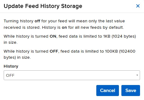
while True: time.sleep(1)Main Capture Loop
Continuous image capture and transmission loop with dynamic memory management and error handling.
Process Flow:
- Initializes with small buffer size (15KB) for memory-constrained environment
- Continuously captures images from camera
- Transmits images via selected protocol (HTTP or MQTT)
- Implements adaptive buffer sizing based on memory availability
- Includes comprehensive error recovery mechanisms
Key Operations:
Image Capture:
- Allocates bytearray buffer for image storage
- Captures JPEG image from OV2640 camera
- Validates captured image has sufficient data (>100 bytes)
Data Processing:
- Encodes image data to Base64 format for text-based transmission
- Base64 encoding ensures safe data transfer through text-based protocols
Data Transmission:
- MQTT Mode: Publishes encoded image to Adafruit IO feed
- HTTP Mode: Sends encoded image via HTTP POST request
- Mode-specific transmission based on user selection
Dynamic Memory Management:
- Buffer Expansion: Increases buffer size when image approaches current limit
- Buffer Reduction: Decreases buffer size on memory errors
- Memory Limits: Buffer ranges from 10KB to 25KB
- Garbage Collection: Explicit memory cleanup after each cycle
buffer_size = 15000  # Start with 15KB buffer for memory efficiency

while True:
    try:
        # Allocate buffer and capture image
        buf = bytearray(buffer_size)
        img = cam.capture(buf)

        # Process image if valid
        if img and len(img) > 100:
            print(f"Captured: {len(img)} bytes")
            encoded = binascii.b2a_base64(img).strip()

            # Transmit via selected protocol
            if Mode == "MQTT":
                mqtt_client.publish(img_feed, encoded)
            else:
                http_io.send_data("img", encoded.decode('utf-8'))

            # Adaptive buffer sizing
            if len(img) > buffer_size - 1000:
                buffer_size = min(buffer_size + 2000, 25000)

        # Memory cleanup
        del img, buf, encoded
        gc.collect()

    except MemoryError:
        print("Memory error - reducing buffer")
        buffer_size = max(10000, buffer_size - 5000)
        gc.collect()
    except Exception as e:
        print(f"Error: {e}")

    time.sleep(3)  # Loop delay
Step 5: Features and Benefits
- Dual protocol support (HTTP/MQTT)
- Adaptive memory management
- Real-time image transmission
- Robust error recovery
- Hardware camera/ethernet integration
Step 6: Video Demonstration
Coming Soon
Conclusion
This IoT image capture system successfully demonstrates:
- Reliable camera-to-cloud transmission on W6300-EVB-PICO2
- Effective memory management for constrained environments
- Flexible protocol support for different deployment needs
- Practical foundation for embedded vision applications
The solution balances performance with resource constraints, providing a versatile platform for various IoT vision use cases.
-
Codes

-
Schematic
