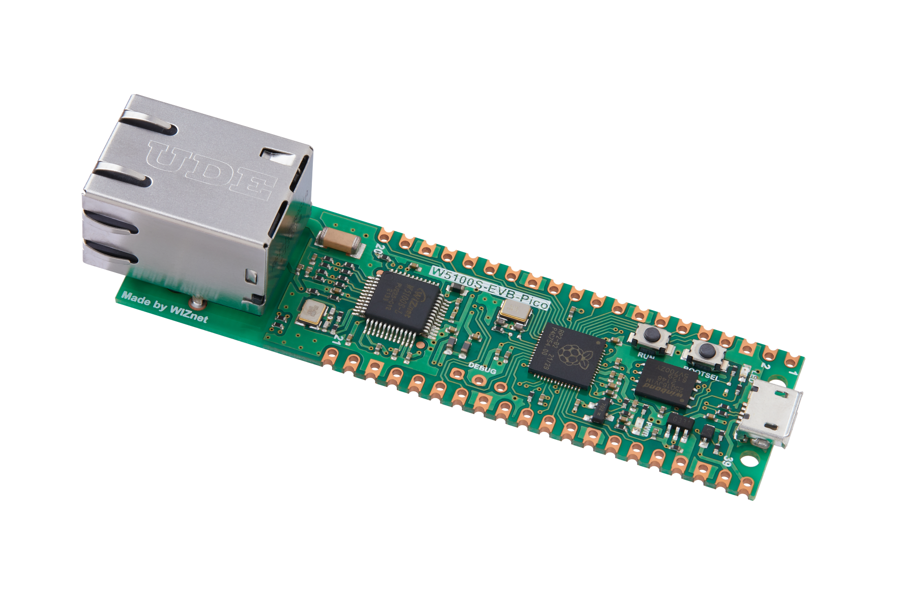
Ethernet CAN Gateway
Ethernet CAN Gateway
Microchip - MCP2515
x 1
CAN module
- OLED
x 1
For display info
- Button
x 2
- LED
x 2
Indicator
- Resistor (220)
x 2
For LED
GENIVI Alliance - CANdevStudio
x 1
opensource GUI tool for CAN
QT Group - QCanBus
x 1
opensource Qt plug-in
For more readable page, Click me!
Overview
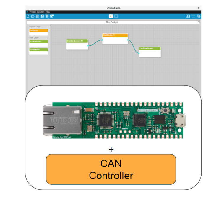
There are many tools for controlling CAN devices. Among them, there is one of the open-source projects called Qt-based CANDevStudio. CANDev Studio uses a common plug-in called Qt CAN plug-in, which can be used on a Qt basis. However, there was no plug-in here between CAN and Ethernet heterogeneous protocols except Virtual. So, we wanted to create a plug-in that can be used on the Qt base and a gateway that can control CAN devices via Etherent through that plug-in, and that's the project.Component Diagram
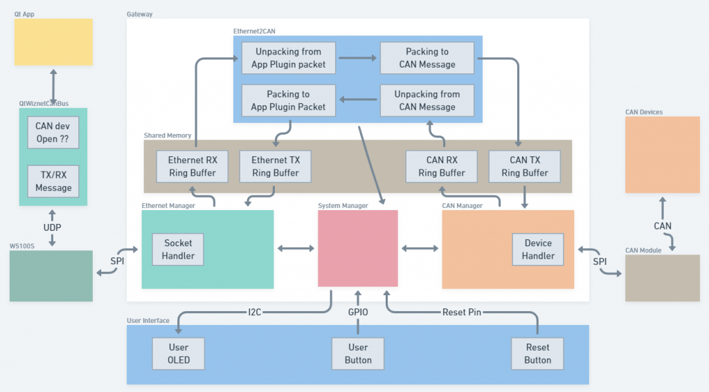
What should be done in the project was clear, as explained in Overview. Therefore, we decided to draw a component diagram to clarify what needs to be done, and to figure out if there is any problem with the composition first.- Qt App: Qt-based application with GUI to control CAN devices easily.
- QtWiznetCanBus: A plug-in which use in Qt-based applications.
- W5100S: The main character of this project. For Ethernet.
- Gateway: Firmware running on WIZnet W5100S-Pico-EVB board to handle Ethernet packets, CAN packets and etc.
- User Interface: Hardware interfaces to use firmware on the board easily.
Hardware
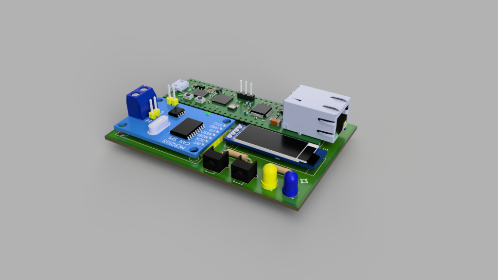
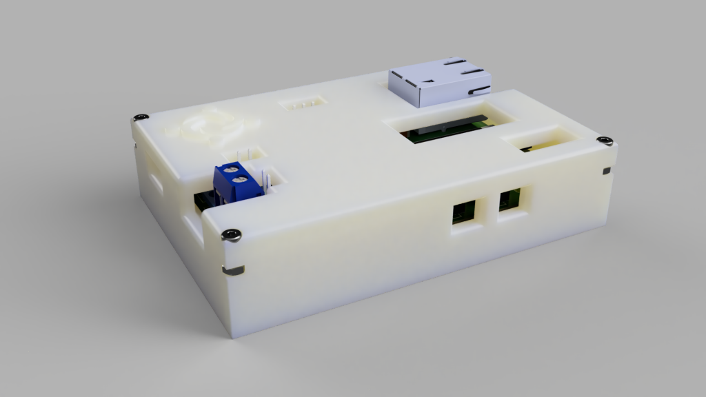
We determined the necessary hardware configuration from the diagram above, and designed and built a PCB/case for a more compact design and configuration.
| Main Part | Qty | Note |
|---|---|---|
| W5100S-EVB-Pico | 1 | MCU with W5100S for ethernet |
| MCP2515 CAN | 1 | CAN module (w/ transceiver) |
| OLED | 1 | Display device information (network, etc.) |
| LED | 2 | TX/RX Indicator |
| Resister | 2 | (220Ω) For LED voltage |
| Button | 2 |
PCB 3D model
Case 3D model
Software
The software was used as a combination of WIZnet ioLibrary + pico + CMake to minimize platform dependence.
Cores
Since the PICO has dual core, roles of these cores are separated as shown below for smooth packet processing.
| Core 0 | Core 1 |
|---|---|
| SystemManager | |
| (OLED, UserButton) | Ethernet Manager |
| CAN Manager | |
| Ethernet2CAN |
Shared Memory
We implemented queue buffers in shared memory between two cores to allow each manager (CAN, Ethernet) to operate non-blocking.
Event-Based Socket
In the case of Ethernet Socket, it was created based on Event, making it possible to operate differently depending on the OnWritable() and OnReadable() implementations.
However, due to the nature of the project's configuration, it is made to create only a single socket, so if you want to create multiple sockets, you need to modify the object more extensively.
QtCanBus Plug-in (Only UDP)
We referred to the Cannelloni Can Bus plug-in project, which used the Cannelloni protocol, and created a more general plug-in that could be used without Cannelloni.

Results


Development Notes (Korean)
- [WIZnet CAN] 프로젝트 시작 이야기
- [WIZnet CAN] W5100S-EVB-Pico OLED/DHCP 시험
- [WIZnet CAN] QtCanBus 플러그인 만들기
- [WIZnet CAN] 프로토타입 제작
- [WIZnet CAN] 통신 구현/PCB/케이스 디자인
- [WIZnet CAN] PCB 제작 및 조립
- [WIZnet CAN] 케이스 조립
- [WIZnet CAN] 펌웨어 빌드 및 다운로드 하기
- [WIZnet CAN] Qt 플러그인 빌드 및 실행
- [WIZnet CAN] CANdevStudio 빌드 및 실행
Step by Step Guide
Step 0. Get your parts
| Main Part | Qty | Note |
|---|---|---|
| W5100S-EVB-Pico | 1 | MCU with W5100S for ethernet |
| MCP2515 CAN | 1 | CAN module (w/ transceiver) |
| OLED | 1 | Display device information (network, etc.) |
| LED | 2 | TX/RX Indicator |
| Resister | 2 | (220Ω) For LED voltage |
| Button | 2 |
Step 1. Assembly parts
Pin Map


| PICO Board Pin No. | GPIO | Function | MCP2515 | MCP2515 Pin No. |
|---|---|---|---|---|
| 10 | GPIO7 | GPIO | INT | 1 |
| 14 | GPIO10 | SPI1 SCK | SCK | 2 |
| 15 | GPIO11 | SPI1 MOSI | SI | 3 |
| 16 | GPIO12 | SPI1 MISO | SO | 4 |
| 17 | GPIO13 | GPIO | CS | 5 |
| GND | GND | 6 | ||
| 39 | VSYS | 3.3V | VCC | 7 |

| PICO Board Pin No. | GPIO | Function | OLED | OLED Pin No. |
|---|---|---|---|---|
| 19 | GPIO14 | I2C1 SDA | SDA | 4 |
| 20 | GPIO15 | I2C1 SCL | SCL | 3 |
| 36 | 3.3V | VCC | 2 | |
| GND | GND | GND | 1 |
| PICO Board Pin No. | GPIO | 비고 |
|---|---|---|
| 30 | RUN |
| PICO Board Pin No. | GPIO | 비고 |
|---|---|---|
| 9 | GPIO6 | Low Active |
| PICO Board Pin No. | GPIO | Note |
|---|---|---|
| 4 | GPIO2 | Low Active |
| 5 | GPIO3 | Low Active |
(method 1) Using Breadboard

(method 2) Circuit board


(method 2) PCB - more expensive but compact

Step 2. (Optional) Housing


Step 3. Build & Download Firmware (CMake based Project)
Installation
- Install VS Code
- Install git
- Install cmake
- Install python to download firmware
- Install ARM GCC compiler
- Install windows build tools (for only Windows)
- Install MinGW GCC (for only Windows)
Set environment
- VS Code path in your workspace or entire system (official manual)
- For ARM gcc compiler, (only Windows) windows build tools, MinGW GCC
# for linux -> env.linux
# for macOS -> env.osx
"terminal.integrated.env.windows": {
        "PATH": "${env:PATH};D:/tools/build_tools/xpack-windows-build-tools-4.2.1-2/bin;C:/fw/tools/xpack-arm-none-eabi-gcc-10.2.1-1.1/bin;D:/tools/mingw32/bin",
},
Clone code from repository
cd
git clone git@github.com:RRTstar/wiznet_can_gateway.git
cd wiznet_can_gateway
git submodule update --init
cd external\\pico-sdk
git submodule update --init
Build
cd wiznet_can_gateway
cmake -S . -B build -G "MinGW Makefiles" -DPICO_BOARD=pico
cmake --build build -j4
Download (Just Drag & Drop)


Step 4. Build Qt GUI Plug-in
Install Qt 5.15.2
- (Only for windows) CHECK MinGW 8.1.0 64bit for additional installation
Clone code
git clone git@github.com:RRTstar/QtWiznetCanBus.git
Open Project & Build
- Execute Qt Creator
- Select [File] → [Open File or Project] on top menu bar

- Select & Open [CMakeLists.txt] in the folder cloned above.

- Configure Project (depend on your environment)
- MinGW is for just only Windows

- Opened! Yeeeeeah!!

- Build
Crtl + B # shortcut

Copy dll file to Qt plugins folder


Test Plug-in
- Open CAN Bus example (default by Qt)

- Build & Run
Crtl + B  # For build
Crtl + R  # For run
- Select wiznet_can

- Enter your devices IP Address:Port (Check your OLED on your device)


Step 5. Build CANdevStudio
Clone code
git clone --recursive git@github.com:GENIVI/CANdevStudio.git
Open Project & Build & Run
- Execute Qt Creator
- Select [File] → [Open File or Project] on top menu bar
- Select & Open [CMakeLists.txt] in the folder cloned above.
- Build & Run
Crtl + B  # For build
Crtl + R # For run- Select [New Project...]


- Enter your devices IP Address:Port (Check your OLED on your device)

- Add & connect [CanRawVeiw] component to view CAN messages received.

- Check operation status

-
wiznet_can_gateway
firmware
-
QtWiznetCanBus
Qt plug-in for CAN UDP
-
Expansion Board
for compact
-
Expansion Board Gerber
gerber file
-
Case
for compact

