
SyncBox RTX-16-S3
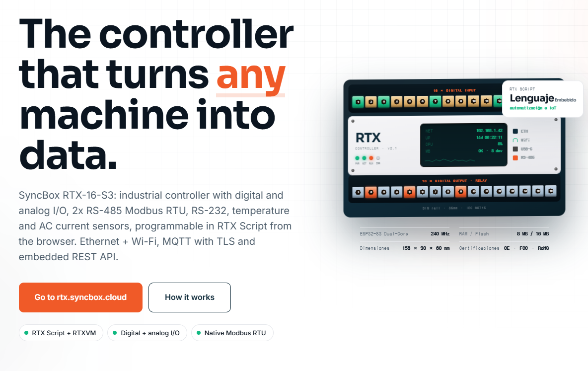
SyncBox RTX-16-S3: industrial controller, Ethernet + Wi-Fi, MQTT with TLS and embedded REST API.
1) Introduction
Industrial machines generate valuable signals every second: digital ON/OFF states, relay events, temperature values, current consumption, pressure readings, flow data, and Modbus registers from meters or drives. The challenge is not only reading these signals, but also converting them into reliable, structured data that can be used by dashboards, maintenance systems, production analytics, and cloud platforms.
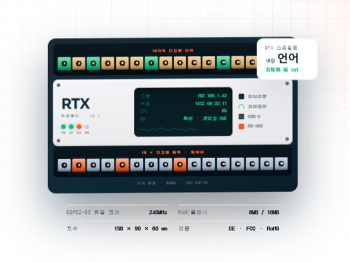
The RTX-16-S3 is designed for this purpose. It is an industrial edge IoT controller that combines machine-side I/O, local logic execution, serial industrial communication, Ethernet, Wi-Fi, MQTT, and an embedded REST API. According to the product page, the controller includes 16 digital inputs, 16 relay outputs, analog I/O, two RS-485 Modbus RTU channels, RS-232, temperature sensing, AC current sensing, Ethernet, Wi-Fi, MQTT with TLS, and a browser-based RTX Script environment.
From a WIZnet maker perspective, one of the most important points is that the RTX-16-S3 uses WIZnet W5500 Ethernet for wired network connectivity. The W5500 is a hardwired TCP/IP Ethernet controller with integrated 10/100 Ethernet MAC and PHY, SPI interface, 8 sockets, and 32 KB internal buffer memory, making it suitable for embedded systems that require stable wired networking.
This article explains how an RTX-16-S3-style industrial edge controller can be understood, wired, programmed, and tested. It focuses on the system architecture, industrial interfaces, W5500 Ethernet role, data flow, and example software logic for collecting machine data and publishing it to an MQTT broker.
2) Required Components
Main Hardware
| Component | Purpose |
|---|---|
| RTX-16-S3 industrial controller | Main edge controller for machine I/O, local logic, and data publishing |
| ESP32-S3 MCU | Main processor for control logic, Wi-Fi, USB, and firmware execution |
| WIZnet W5500 Ethernet controller | Wired Ethernet interface for stable industrial network communication |
| 24 VDC power supply | Common industrial power input for sensors and controller-side I/O |
| Digital sensors / machine contacts | Inputs such as start, stop, alarm, door, cycle, counter, or limit switch |
| Relay-controlled loads | Outputs such as lamps, buzzers, contactors, solenoids, or control relays |
| RS-485 Modbus RTU devices | Energy meters, VFDs, temperature controllers, counters, or PLCs |
| RS-232 device | HMI, scale, legacy PLC, barcode reader, or serial equipment |
| Analog sensors | 0–10 V or 4–20 mA sensors for pressure, level, flow, or speed |
| NTC temperature sensors | Local temperature measurement |
| Split-core CT / SCT current sensor | AC current measurement |
| Ethernet cable | Connection to factory LAN, router, industrial switch, or gateway |
| MQTT broker / IoT platform | Receives telemetry and machine events |
The RTX-16-S3 product page specifies an ESP32-S3 dual-core 240 MHz MCU, 8 MB RAM / 16 MB flash, DIN rail mounting, Ethernet, Wi-Fi, USB-C, RS-485, RS-232, 16 digital inputs, and 16 relay outputs.
Optional Development Tools
| Tool | Purpose |
|---|---|
| PC or laptop | Browser-based configuration, monitoring, and programming |
| MQTT Explorer | MQTT topic inspection |
| Modbus Poll / QModMaster | Modbus RTU testing |
| Multimeter | Voltage, continuity, and relay output verification |
| Logic analyzer | SPI, UART, or RS-485 debugging |
| Serial terminal | RS-232 / UART diagnostics |
| Industrial Ethernet switch | Stable LAN connection for factory deployment |
3) Hardware Setup
The RTX-16-S3 is intended to be installed in an electrical panel rather than used as a desktop development board. The product page describes a 35 mm DIN rail form factor and an industrial I/O structure with isolated inputs and relay outputs.
Basic Hardware Flow
The controller performs three main tasks:
- Read machine-side signals
Digital inputs, analog sensors, NTC sensors, CT current sensors, and Modbus devices are connected to the RTX-16-S3. - Process logic at the edge
The controller runs local logic using RTX Script and RTXVM. This allows machine events to be detected without depending on a cloud server. - Publish structured data
Events and telemetry are sent through Ethernet or Wi-Fi using MQTT, REST API, or other firmware-level services.
The product page describes the architecture as a three-layer flow: shop-floor devices, RTX edge processing, and the SyncBox platform for dashboards, alerts, and historical data.
Recommended Installation Steps
- Mount the controller on a DIN rail inside the control panel.
- Connect the 24 VDC power supply.
- Connect digital inputs from machine signals such as cycle start, emergency alarm, running status, and part counter.
- Connect relay outputs only through safe interposing relays or control circuits when switching industrial loads.
- Connect RS-485 A/B lines to Modbus RTU devices.
- Connect Ethernet to the factory LAN using the W5500-based wired interface.
- Configure IP address, MQTT broker, and device identity.
- Deploy RTX Script logic or equivalent firmware logic.
- Test locally before connecting to production dashboards.
Industrial wiring can involve hazardous voltage and machinery. Final installation should be reviewed by qualified electrical or automation personnel.
4) Interface Explanation
4.1 WIZnet W5500 Ethernet Interface
The W5500 is the wired Ethernet communication core of this architecture. It connects to the host MCU through SPI and offloads TCP/IP networking into dedicated hardware. WIZnet describes the W5500 as a hardwired Internet controller with integrated full TCP/IP stack, 10/100 Ethernet MAC and PHY, SPI interface up to 80 MHz, 8 sockets, and 32 KB internal memory.
For industrial IoT, wired Ethernet is often preferred because it provides:
- More stable connectivity than Wi-Fi in noisy factory environments
- Easier integration with industrial switches and VLANs
- Predictable network behavior for MQTT, REST API, and local dashboards
- Reduced RF dependency in metal cabinets or dense production areas
In an RTX-16-S3-style design, the ESP32-S3 can handle application logic while the W5500 manages low-level Ethernet communication.
4.2 SPI Interface
The W5500 communicates with the MCU over SPI. A typical SPI connection includes:
| Signal | Description |
|---|---|
| SCK | SPI clock from MCU to W5500 |
| MOSI | Data from MCU to W5500 |
| MISO | Data from W5500 to MCU |
| CS | Chip select |
| INT | Optional interrupt line |
| RST | Optional hardware reset |
| 3.3 V | Power |
| GND | Ground |
The exact internal RTX-16-S3 PCB pin mapping is not published on the product page, so external wiring should follow the official hardware documentation if available. For maker prototyping, an ESP32-S3 development board and W5500 module can be connected using the SPI table in Section 5.
4.3 RS-485 Modbus RTU
RS-485 is used for long-distance, noise-resistant industrial serial communication. The RTX-16-S3 includes two isolated RS-485 channels and supports Modbus RTU functions according to the product page.
Typical devices connected through RS-485 include:
- Energy meters
- Variable frequency drives
- Temperature controllers
- Flow meters
- Weighing controllers
- PLCs with Modbus RTU support
The controller can periodically read Modbus registers, convert raw values into engineering units, and publish them as MQTT telemetry.
4.4 RS-232 / UART
RS-232 is useful for legacy industrial equipment, scales, barcode readers, HMIs, and serial instruments. The RTX-16-S3 product page lists RS-232 UART support for HMIs, PLCs, and scales.
4.5 Digital Inputs
The controller provides 16 digital inputs. The product page describes these as 24 V digital inputs using PCF8574-based I/O expansion with isolation.
Common input examples:
- Machine running
- Cycle start
- Cycle complete
- Alarm active
- Door open
- Emergency stop status
- Part counter pulse
- Sensor detection
4.6 Relay Outputs
The RTX-16-S3 provides 16 relay outputs. The product page lists relay outputs rated at 10 A / 250 VAC.
Relay outputs can be used to control:
- Stack lights
- Buzzers
- Signal relays
- Solenoid control relays
- Auxiliary indicators
- Machine enable circuits
For production machines, relay outputs should be designed with proper fusing, contact protection, isolation, and safety review.
4.7 Analog I/O and Sensors
The RTX-16-S3 product page lists analog input support for 0–10 V and 4–20 mA, analog output support for 0–10 V, 0–5 V, and 0–25 mA, two NTC temperature channels, and AC current measurement using split-core CT sensors.
These interfaces are useful for:
- Pressure monitoring
- Tank level monitoring
- Flow measurement
- Motor current trend monitoring
- Temperature monitoring
- Valve or drive command output
4.8 MQTT, REST API, and SSE
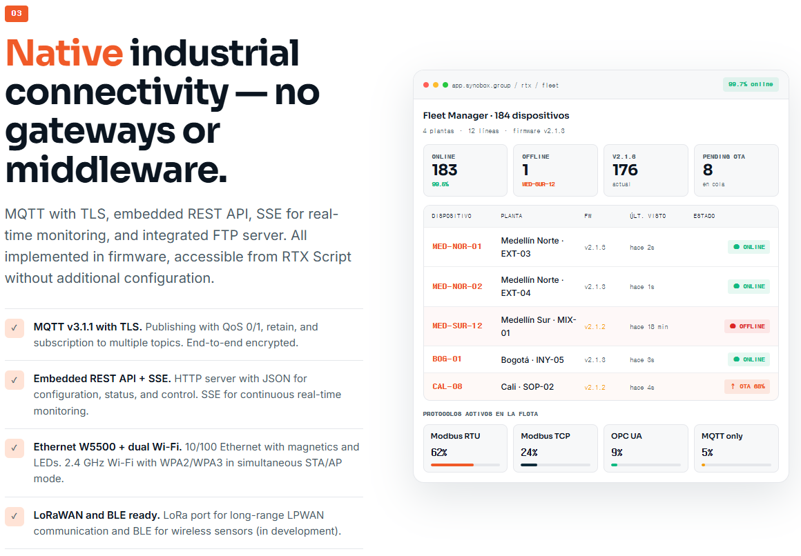
The product page states that the RTX-16-S3 supports MQTT v3.1.1 with TLS, embedded REST API, SSE for real-time monitoring, FTP, Ethernet, and dual Wi-Fi.
A practical architecture is:
- MQTT for telemetry and event publishing
- REST API for configuration and status reading
- SSE for live browser monitoring
- Local buffer for temporary offline data storage
- OTA for firmware and script deployment
5) Wiring Table
5.1 Industrial Field Wiring Example
| RTX Terminal / Interface | Field Device | Signal Type | Notes |
|---|---|---|---|
| DI1 | Machine RUN contact | 24 V digital input | Detects machine running state |
| DI2 | Cycle complete pulse | 24 V digital input | Used for cycle counting |
| DI3 | Alarm output | 24 V digital input | Publishes alarm event |
| DI4 | Door sensor | 24 V digital input | Safety/status monitoring only |
| DO1 | Stack light green | Relay output | Machine healthy indication |
| DO2 | Stack light red | Relay output | Alarm indication |
| DO3 | Buzzer relay | Relay output | Audible alert |
| AI1 | Pressure sensor | 4–20 mA | Convert to engineering unit |
| AI2 | Level sensor | 0–10 V | Tank or material level |
| NTC1 | Cabinet temperature | NTC | Internal panel temperature |
| CT1 | Motor current CT | 0–50 A CT input | Current trend monitoring |
| RS-485 CH1 | Energy meter | Modbus RTU | Read voltage, current, power |
| RS-485 CH2 | VFD | Modbus RTU | Read frequency, status, fault |
| RS-232 | Scale or HMI | UART | Legacy serial integration |
| Ethernet | Factory switch | W5500 Ethernet | MQTT / REST / dashboard |
5.2 ESP32-S3 + W5500 Maker Prototype Wiring
This table is for a maker prototype that reproduces the Ethernet portion using an ESP32-S3 development board and W5500 module. It does not represent the undisclosed internal RTX-16-S3 PCB routing.
| ESP32-S3 Pin | W5500 Pin | Description |
|---|---|---|
| 3.3 V | VCC | W5500 logic power |
| GND | GND | Common ground |
| GPIO12 | SCK | SPI clock |
| GPIO11 | MOSI | SPI MOSI |
| GPIO13 | MISO | SPI MISO |
| GPIO10 | CS | SPI chip select |
| GPIO9 | RST | Optional reset |
| GPIO8 | INT | Optional interrupt |
Pin numbers can be changed depending on the selected ESP32-S3 board.
6) Software Environment Setup
6.1 RTX-16-S3 Browser-Based Setup
The RTX-16-S3 product page describes a browser-based IDE served by the controller and a scripting environment called RTX Script running on RTXVM. It also lists native functions such as Modbus read/write, digital I/O access, and telemetry publishing.
A typical setup flow is:
- Power the controller.
- Connect Ethernet or Wi-Fi.
- Open the controller IP address in a browser.
- Configure device name, network settings, and MQTT broker.
- Create an RTX Script application.
- Map I/O channels to meaningful names.
- Add Modbus slave IDs and register addresses.
- Deploy the script.
- Monitor live variables and logs.
- Confirm MQTT messages are received by the server.
6.2 Maker Prototype Setup with Arduino IDE
For a simplified ESP32-S3 + W5500 test, install:
- Arduino IDE
- ESP32 board package
- Ethernet library with W5500 support
- PubSubClient library
- MQTT broker such as Mosquitto
This setup is useful for verifying the W5500 Ethernet data path before moving to a full industrial controller.
7) Full Code Examples
Example 1: RTX Script-Style Machine Monitoring Logic
The following example is written in an RTX Script-style format based on the functions shown on the RTX-16-S3 product page. Function names may need adjustment depending on the actual firmware version.
// RTX-16-S3 Machine Monitoring Example
// Purpose:
// - Read machine digital inputs
// - Read temperature
// - Read Modbus energy value
// - Control relay outputs
// - Publish telemetry and events through MQTT

DEVICE_ID = "RTX_LINE_01"
TEMP_LIMIT_WARNING = 70
TEMP_LIMIT_ALARM = 85
CYCLE_TOPIC = "factory/line01/cycle"
TELEMETRY_TOPIC = "factory/line01/telemetry"
ALARM_TOPIC = "factory/line01/alarm"

// Digital input mapping
DI_RUN = 1
DI_CYCLE = 2
DI_ALARM = 3
DI_DOOR = 4

// Relay output mapping
DO_GREEN_LIGHT = 1
DO_RED_LIGHT = 2
DO_BUZZER = 3

// Modbus device mapping
ENERGY_METER_ID = 1
REG_ACTIVE_POWER = 0x0000
REG_TOTAL_ENERGY = 0x0002

last_cycle_state = 0
cycle_count = 0

function setup() {
    mqtt_pub("factory/line01/status", "boot")
    do_write(DO_GREEN_LIGHT, 0)
    do_write(DO_RED_LIGHT, 0)
    do_write(DO_BUZZER, 0)
}

function loop() {
    run_state = di_read(DI_RUN)
    cycle_state = di_read(DI_CYCLE)
    alarm_state = di_read(DI_ALARM)
    door_state = di_read(DI_DOOR)

    cabinet_temp = ntc_read(1)

    active_power = modbus_read(ENERGY_METER_ID, REG_ACTIVE_POWER)
    total_energy = modbus_read(ENERGY_METER_ID, REG_TOTAL_ENERGY)

    // Rising edge detection for cycle count
    if cycle_state == 1 && last_cycle_state == 0 {
        cycle_count = cycle_count + 1

        mqtt_pub(CYCLE_TOPIC, {
            "device": DEVICE_ID,
            "event": "cycle_complete",
            "cycle_count": cycle_count,
            "temperature": cabinet_temp,
            "active_power": active_power
        })
    }

    last_cycle_state = cycle_state

    // Machine status indication
    if run_state == 1 && alarm_state == 0 {
        do_write(DO_GREEN_LIGHT, 1)
        do_write(DO_RED_LIGHT, 0)
        do_write(DO_BUZZER, 0)
    }

    if alarm_state == 1 {
        do_write(DO_GREEN_LIGHT, 0)
        do_write(DO_RED_LIGHT, 1)
        do_write(DO_BUZZER, 1)

        mqtt_pub(ALARM_TOPIC, {
            "device": DEVICE_ID,
            "event": "machine_alarm",
            "door_open": door_state,
            "temperature": cabinet_temp
        })
    }

    // Temperature warning
    if cabinet_temp > TEMP_LIMIT_WARNING {
        mqtt_pub(ALARM_TOPIC, {
            "device": DEVICE_ID,
            "event": "cabinet_temp_warning",
            "temperature": cabinet_temp
        })
    }

    // Temperature alarm
    if cabinet_temp > TEMP_LIMIT_ALARM {
        do_write(DO_RED_LIGHT, 1)
        do_write(DO_BUZZER, 1)

        mqtt_pub(ALARM_TOPIC, {
            "device": DEVICE_ID,
            "event": "cabinet_temp_alarm",
            "temperature": cabinet_temp
        })
    }

    // Periodic telemetry
    mqtt_pub(TELEMETRY_TOPIC, {
        "device": DEVICE_ID,
        "run": run_state,
        "alarm": alarm_state,
        "door": door_state,
        "cycle_count": cycle_count,
        "temperature": cabinet_temp,
        "active_power": active_power,
        "total_energy": total_energy
    })

    delay(1000)
}
Example 2: ESP32-S3 + W5500 MQTT Test Code
This Arduino example is for a maker prototype using ESP32-S3 and a W5500 Ethernet module. It publishes test telemetry to an MQTT broker over wired Ethernet. It is intended for lab testing, not direct industrial safety control.
#include <SPI.h>
#include <Ethernet.h>
#include <PubSubClient.h>

// -----------------------------
// W5500 SPI Pin Configuration
// Change these pins for your ESP32-S3 board.
// -----------------------------
#define W5500_SCK   12
#define W5500_MOSI  11
#define W5500_MISO  13
#define W5500_CS    10
#define W5500_RST   9

// -----------------------------
// Network Configuration
// -----------------------------
byte mac[] = { 0x02, 0x57, 0x49, 0x5A, 0x55, 0x01 };

// Static IP example
IPAddress ip(192, 168, 1, 42);
IPAddress dnsServer(8, 8, 8, 8);
IPAddress gateway(192, 168, 1, 1);
IPAddress subnet(255, 255, 255, 0);

// MQTT broker
const char* mqttServer = "192.168.1.100";
const uint16_t mqttPort = 1883;

const char* deviceId = "esp32s3-w5500-line01";
const char* telemetryTopic = "factory/line01/telemetry";
const char* statusTopic = "factory/line01/status";

// -----------------------------
// Clients
// -----------------------------
EthernetClient ethClient;
PubSubClient mqttClient(ethClient);

// -----------------------------
// Simulated I/O
// Replace these with real GPIO,
// Modbus, ADC, or sensor values.
// -----------------------------
uint32_t cycleCount = 0;
unsigned long lastPublish = 0;

void resetW5500() {
  pinMode(W5500_RST, OUTPUT);
  digitalWrite(W5500_RST, LOW);
  delay(100);
  digitalWrite(W5500_RST, HIGH);
  delay(300);
}

void connectMQTT() {
  while (!mqttClient.connected()) {
    Serial.print("Connecting to MQTT... ");

    if (mqttClient.connect(deviceId)) {
      Serial.println("connected");
      mqttClient.publish(statusTopic, "online", true);
    } else {
      Serial.print("failed, rc=");
      Serial.println(mqttClient.state());
      delay(3000);
    }
  }
}

void setup() {
  Serial.begin(115200);
  delay(1000);

  Serial.println();
  Serial.println("ESP32-S3 + W5500 MQTT Test");

  resetW5500();

  SPI.begin(W5500_SCK, W5500_MISO, W5500_MOSI, W5500_CS);
  Ethernet.init(W5500_CS);

  Ethernet.begin(mac, ip, dnsServer, gateway, subnet);
  delay(1000);

  Serial.print("IP Address: ");
  Serial.println(Ethernet.localIP());

  if (Ethernet.hardwareStatus() == EthernetNoHardware) {
    Serial.println("W5500 hardware was not found.");
    while (true) {
      delay(1000);
    }
  }

  if (Ethernet.linkStatus() == LinkOFF) {
    Serial.println("Ethernet cable is not connected.");
  }

  mqttClient.setServer(mqttServer, mqttPort);
  connectMQTT();
}

void loop() {
  if (!mqttClient.connected()) {
    connectMQTT();
  }

  mqttClient.loop();

  unsigned long now = millis();

  if (now - lastPublish >= 1000) {
    lastPublish = now;

    // Simulated machine values
    cycleCount++;
    float temperature = 42.5 + (cycleCount % 10) * 0.1;
    int runState = 1;
    int alarmState = 0;

    char payload[256];
    snprintf(payload, sizeof(payload),
             "{\"device\":\"%s\",\"cycle_count\":%lu,"
             "\"temperature\":%.2f,\"run\":%d,\"alarm\":%d}",
             deviceId,
             (unsigned long)cycleCount,
             temperature,
             runState,
             alarmState);

    bool ok = mqttClient.publish(telemetryTopic, payload);

    Serial.print("Publish: ");
    Serial.print(ok ? "OK " : "FAIL ");
    Serial.println(payload);
  }
}
For production systems, MQTT over TLS, credential management, certificate validation, watchdog handling, offline buffering, and secure OTA update policy should be added.
8) Testing Steps
Step 1: Power and Network Check
Confirm that the controller powers on correctly and receives a valid IP address. The RTX-16-S3 product page shows Ethernet, Wi-Fi, USB-C, and local browser access as part of the controller workflow.
Checklist:
- Power LED is active
- Ethernet link LED is active
- IP address is reachable
- Browser IDE or REST endpoint responds
- MQTT broker is reachable from the same network
Step 2: Digital Input Test
Apply a safe 24 V signal to each digital input one at a time.
Expected result:
- DI state changes in the live monitor
- MQTT telemetry reflects the updated input state
- Cycle counter increments only on the intended edge
Step 3: Relay Output Test
Activate each relay output with no load first.
Expected result:
- Relay click is heard
- Output state changes in monitoring UI
- Multimeter confirms contact operation
After dry testing, connect the actual control circuit through proper protection.
Step 4: Modbus RTU Test
Connect an RS-485 Modbus device.
Test items:
- Slave ID
- Baud rate
- Parity
- Stop bits
- Register address
- Register type
- Scaling factor
Expected result:
- Register values are read consistently
- Timeout and CRC errors remain low
- MQTT payload includes Modbus values
Step 5: Analog Input Test
Inject known analog values.
Examples:
- 4 mA, 12 mA, 20 mA for 4–20 mA input
- 0 V, 5 V, 10 V for 0–10 V input
Expected result:
- Raw ADC value changes smoothly
- Engineering unit conversion is correct
- Alarm thresholds trigger at expected values
Step 6: MQTT Test
Use MQTT Explorer or Mosquitto client.
Example topic structure:
factory/line01/status
factory/line01/telemetry
factory/line01/cycle
factory/line01/alarm
factory/line01/config
Expected result:
- Telemetry publishes periodically
- Event messages publish only when events occur
- Retained status message shows online/offline state
- Payload is valid JSON
Step 7: Network Failover Test
Disconnect Ethernet temporarily.
Expected result:
- Local control logic continues running
- Buffer stores recent events if supported
- MQTT reconnects when the network returns
- No duplicate cycle events are published
The RTX-16-S3 product page describes edge execution and local buffering as part of the controller architecture.
9) Troubleshooting
| Problem | Possible Cause | Solution |
|---|---|---|
| Controller has no IP address | Ethernet cable, switch, DHCP, or static IP issue | Check cable, switch port, subnet, and IP configuration |
| MQTT does not connect | Broker IP, port, firewall, TLS, or credentials issue | Test broker from PC, confirm port, check username/password |
| W5500 not detected in prototype | SPI wiring or CS pin mismatch | Verify SCK, MOSI, MISO, CS, 3.3 V, and GND |
| Ethernet link is down | Cable or magnetics issue | Try another cable and switch port |
| Digital input always ON | Incorrect 24 V wiring or shared ground issue | Confirm input wiring and field voltage |
| Relay output does not switch load | Wrong contact terminal or load wiring | Test relay with multimeter before connecting load |
| Modbus timeout | Wrong baud rate, parity, slave ID, or A/B polarity | Swap A/B, check serial settings, test one slave at a time |
| Modbus values look incorrect | Wrong register address or data format | Check zero-based vs one-based addressing and word order |
| Analog value unstable | Noise, grounding, or scaling issue | Use shielded cable, filter input, confirm sensor supply |
| Temperature reading incorrect | Wrong NTC curve or divider value | Calibrate with known temperature points |
| Duplicate cycle counts | Input bounce or pulse edge handling issue | Add debounce and rising-edge detection |
| MQTT payload too large | Excessive JSON fields or frequent publish rate | Reduce payload size or publish interval |
10) Use Cases & Market Potential
10.1 Production Monitoring
The RTX-16-S3 can collect cycle signals, machine running state, downtime alarms, and production counts. This makes it suitable for real-time production dashboards and OEE-style monitoring.
10.2 Predictive Maintenance
By combining motor current, temperature, vibration-related signals, and Modbus data from drives or meters, the controller can detect abnormal trends before a machine stops unexpectedly.
10.3 Energy Monitoring
Using RS-485 Modbus energy meters and CT current sensors, the controller can publish energy data per line, machine, or process. This helps factories understand energy consumption patterns.
10.4 Quality and Process Data Collection
Analog sensors such as pressure, level, flow, and temperature can be connected to production processes. These values can be timestamped and sent to quality dashboards or process history systems.
10.5 Legacy Machine Connectivity
Many factories operate machines that do not have modern Ethernet or cloud connectivity. A controller with digital I/O, RS-485, RS-232, Ethernet, MQTT, and REST API can act as a practical bridge between legacy equipment and modern industrial software.
10.6 Why W5500 Matters in This Market
Industrial IoT devices often need long-term stable Ethernet communication. W5500 is valuable because it offloads TCP/IP processing from the MCU, provides 10/100 Ethernet MAC/PHY, supports multiple hardware sockets, and communicates through SPI.
This allows the main MCU to focus on machine logic, I/O scanning, Modbus polling, and telemetry formatting instead of managing the full network stack in software.
11) Module/Chip Technical Overview
11.1 ESP32-S3 Overview
The RTX-16-S3 product page lists the MCU as an ESP32-S3 Dual-Core LX7 running at 240 MHz. Espressif also describes the ESP32-S3 as a dual-core Xtensa LX7 MCU capable of 240 MHz operation with integrated 2.4 GHz Wi-Fi and Bluetooth 5 LE connectivity.
In this project architecture, the ESP32-S3 is responsible for:
- Running application firmware
- Executing local control logic
- Reading digital and analog I/O
- Handling Modbus RTU communication
- Managing Wi-Fi and USB functions
- Coordinating Ethernet communication through W5500
- Running OTA and diagnostics features
11.2 WIZnet W5500 Overview
The W5500 is a dedicated Ethernet controller designed for embedded systems. It integrates:
- Hardwired TCP/IP stack
- 10/100 Ethernet MAC and PHY
- SPI interface
- 8 independent sockets
- 32 KB internal Tx/Rx buffer
- TCP, UDP, ICMP, IPv4, ARP, IGMP, and PPPoE support
- Wake-on-LAN over UDP
- Power-down mode
These features are listed by WIZnet in the official W5500 product documentation.
Why use W5500 instead of software-only networking?
In industrial control systems, the MCU must often perform several tasks at the same time: scan inputs, update outputs, poll Modbus devices, process alarms, maintain watchdogs, and publish network data. A hardwired Ethernet controller reduces the firmware burden by handling Ethernet and TCP/IP functions in silicon.
This is especially useful when:
- The MCU has limited memory
- The application requires predictable network behavior
- The device must maintain multiple socket connections
- The firmware should remain simple and maintainable
- Wired Ethernet is required for factory deployment
11.3 RTX-16-S3 System Overview
Based on the product page, the RTX-16-S3 integrates the following major blocks:
| Block | Description |
|---|---|
| MCU | ESP32-S3 dual-core 240 MHz |
| Ethernet | WIZnet W5500 10/100 Ethernet |
| Wireless | Wi-Fi WPA2/WPA3, STA/AP mode |
| Digital Input | 16 × 24 V inputs |
| Digital Output | 16 × relay outputs |
| Analog Input | 0–10 V / 4–20 mA |
| Analog Output | 0–10 V / 0–5 V / 0–25 mA |
| Temperature | 2 × NTC channels |
| Current | SCT split-core CT input, 0–50 A range |
| Serial | 2 × isolated RS-485, RS-232 UART |
| Protocols | Modbus RTU, MQTT, REST API, SSE |
| Programming | Browser-based RTX Script and RTXVM |
| Mounting | 35 mm DIN rail |
The product page also describes OTA deployment, versioning, live debug, MQTT publishing, REST API access, and edge execution as part of the RTX software environment.
12) Conclusion
The RTX-16-S3 represents a practical industrial edge IoT architecture: it connects directly to machines, reads both simple and complex industrial signals, executes local logic, and publishes structured data through modern network protocols.
For WIZnet makers, the most interesting part is the use of WIZnet W5500 Ethernet. By adding a hardwired TCP/IP Ethernet controller to an ESP32-S3-based system, the design gains stable wired networking while keeping the main MCU focused on control logic, Modbus communication, I/O processing, and telemetry generation.
This architecture is well suited for:
- Industrial IoT gateways
- Machine monitoring systems
- Legacy equipment modernization
- Edge data acquisition
- Modbus-to-MQTT bridges
- Production dashboards
- Predictive maintenance systems
- Energy monitoring platforms
In summary, an ESP32-S3 + W5500 + industrial I/O design can turn machine signals into useful data at the edge. The RTX-16-S3 shows how these building blocks can be packaged into a DIN-rail industrial controller for real factory environments.