
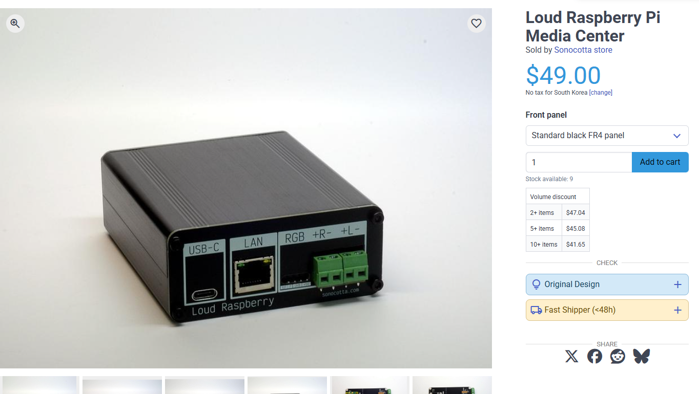
Loud Raspberry Media Center
This versatile media center provides a customizable and fully open-source hardware platform for home entertainment.
1) Introduction
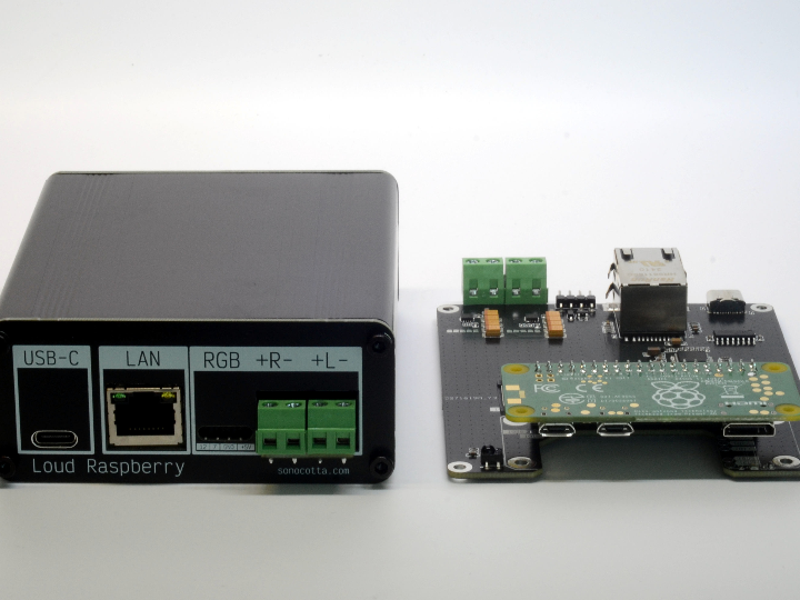
The Loud Raspberry Pi Media Center is a compact network audio device built around a Raspberry Pi Zero / Zero 2 W, a dual MAX98357A I2S DAC with integrated Class-D amplifier, and a WIZnet W5500 SPI Ethernet controller. It is designed as a small but practical home media center that can directly drive passive speakers while also providing reliable wired network connectivity.
Unlike simple Bluetooth speakers or Wi-Fi-only streamers, this design focuses on open hardware, Linux-based audio software, and stable Ethernet streaming. The onboard W5500 gives the Raspberry Pi Zero platform a wired network path through SPI, which is useful for multi-room audio, smart home alerts, TTS playback, and always-on embedded audio nodes.
The board is intended to support software such as Volumio, Mopidy, and custom Raspberry Pi OS-based firmware. The original project notes that enabling the DAC, Ethernet, and IR receiver can be handled with only a few Device Tree overlay lines in the Raspberry Pi boot configuration.
This article explains how the project works, why WIZnet W5500 is useful in a media-center design, how the hardware interfaces are arranged, and how to configure the software stack for testing.
2) Required Components
Main Hardware
| Component | Purpose |
|---|---|
| Loud Raspberry Pi Media Center board | Main carrier board with DAC, amplifier, Ethernet, IR, LED, and connectors |
| Raspberry Pi Zero W or Raspberry Pi Zero 2 W | Linux host system |
| microSD card | Raspberry Pi OS, Volumio, DietPi, or custom image |
| USB-C 5V power adapter | Main power input |
| Passive speakers | Direct speaker output from MAX98357A amplifier |
| Ethernet cable | Wired network connection through W5500 |
| IR remote controller | Optional remote-control input |
| USB serial adapter | Optional debugging and console access |
The Loud Raspberry Pi Media Center version is listed as compatible with Raspberry Pi Zero W and Raspberry Pi Zero 2 W. It uses a dual MAX98357 DAC/amplifier stage and provides 5W per channel into 4Ω or 3W per channel into 8Ω according to the product specification.
Software
Recommended software options:
| Software | Role |
|---|---|
| Raspberry Pi OS | General-purpose Linux base |
| DietPi | Lightweight Linux base |
| Volumio | Audio player distribution |
| Mopidy | Modular music server |
| Snapcast | Multi-room synchronized audio |
| Shairport Sync | AirPlay receiver |
| Squeezelite | Logitech Media Server client |
| Raspotify / librespot | Spotify Connect endpoint |
The project repository also describes Ansible-based provisioning for services such as PulseAudio, Spotify Connect, Snapcast, AirPlay, Squeezelite, UPnP/DLNA, CamillaDSP, and display/LED visualizers.
3) Hardware Setup
The hardware architecture can be understood as four blocks:
- Raspberry Pi Zero host
Runs Linux, audio services, network services, and user applications. - WIZnet W5500 Ethernet controller
Provides SPI-based wired Ethernet connectivity. - MAX98357A I2S DAC/Class-D amplifier
Receives digital audio from Raspberry Pi over I2S and directly drives passive speakers. - User interface peripherals
IR input, RGB LED, relay enable, and serial bridge.
The board receives power from a 5V USB-C power adapter, with the Loud Media Center specification indicating a power requirement of up to 3A. The product page also notes that the Loud boards are intended for passive speakers, not headphones or external amplifiers.
Recommended Setup Flow
- Insert Raspberry Pi Zero / Zero 2 W into the board.
- Connect passive speakers to the speaker terminals.
- Insert a prepared microSD card.
- Connect Ethernet cable to the W5500 Ethernet port.
- Connect 5V USB-C power.
- Boot and verify audio + network interfaces.
4) Interface Explanation
I2S Audio Interface
The MAX98357A uses the Raspberry Pi’s I2S output. I2S separates audio into clock, word select, and data signals:
| Signal | Function |
|---|---|
| I2S CLK | Bit clock for audio data |
| I2S DATA | Digital audio stream |
| I2S WS | Word select / left-right clock |
| DAC EN | Enables or shuts down the amplifier |
For the Loud Raspberry Pi Media Center, the source pinout shows the Raspberry Pi Zero using GPIO18 for I2S clock, GPIO21 for I2S data, GPIO19 for I2S word select, and GPIO4 for MAX98357A enable in the Media Center model.
SPI Ethernet Interface
The W5500 is connected over SPI. In this project, SPI is used for wired Ethernet rather than a display or storage device.
| Signal | Function |
|---|---|
| SPI CLK | Clock from Raspberry Pi to W5500 |
| SPI MOSI | Data from Raspberry Pi to W5500 |
| SPI MISO | Data from W5500 to Raspberry Pi |
| LAN CS | Chip select |
| LAN INT | Interrupt signal |
| LAN RES | Reset signal |
The board pinout lists SPI CLK on BCM11, MOSI on BCM10, MISO on BCM9, LAN reset on BCM24, LAN CS on BCM8, and LAN interrupt on BCM25.
IR Input
The IR receiver input is connected to BCM23. It can be enabled using the Raspberry Pi gpio-ir overlay.
RGB LED
The WS2812 RGB LED signal is connected to BCM12. It can be used for status indication, playback state, boot state, network state, or smart home notifications.
UART / Serial Bridge
The Media Center version includes an onboard serial bridge according to the product comparison table. This is useful for debugging headless installations where HDMI and USB keyboard access are not convenient.
5) Wiring Table
Raspberry Pi Zero Pin Mapping
| Function | Signal | Raspberry Pi BCM GPIO |
|---|---|---|
| I2S clock | I2S CLK | GPIO18 |
| I2S audio data | I2S DATA | GPIO21 |
| I2S word select | I2S WS | GPIO19 |
| DAC enable | DAC EN | GPIO4 |
| SPI clock | SPI CLK | GPIO11 |
| SPI MOSI | SPI MOSI | GPIO10 |
| SPI MISO | SPI MISO | GPIO9 |
| W5500 reset | LAN RES | GPIO24 |
| W5500 chip select | LAN CS | GPIO8 |
| W5500 interrupt | LAN INT | GPIO25 |
| RGB LED | WS2812 | GPIO12 |
| Relay enable | RELAY EN | GPIO7 |
| IR receiver | IR INPUT | GPIO23 |
This wiring follows the published board pinout for the Loud Raspberry Pi Media Center and Raspberry Pi Media Center hardware family.
6) Software Environment Setup
Option A: Raspberry Pi OS
Flash Raspberry Pi OS Lite to the microSD card, then mount the boot partition and edit:
/boot/config.txtFor newer Raspberry Pi OS images, the path may be:
/boot/firmware/config.txtAdd the following lines:
dtoverlay=gpio-ir,gpio_pin=23
dtoverlay=w5500
dtoverlay=max98357a,sdmode-pin=4
These lines enable the IR receiver, W5500 Ethernet controller, and MAX98357A DAC/amplifier. The same overlay configuration is documented in the product page and GitHub project for the Loud Raspberry Pi Media Center.
Then boot the Raspberry Pi and update packages:
sudo apt update
sudo apt upgrade -y
Install audio and network test tools:
sudo apt install -y alsa-utils pulseaudio-utils net-tools iproute2 python3-pipOption B: Volumio
For Volumio, select the appropriate DAC model in the audio settings. The project documentation notes that for HiFi and Loud Raspberry models, Volumio setup is relatively simple because the DACs are supported out of the box; for Loud Raspberry, the relevant DAC setting is Adafruit MAX98357. To enable W5500 Ethernet manually, the documentation shows adding dtoverlay=w5500 to /boot/userconfig.txt.
Example:
[all]
dtoverlay=w5500
Option C: Custom Audio Node
For a custom audio endpoint, install only the services you need:
sudo apt install -y mpd mpc
sudo systemctl enable mpd
sudo systemctl start mpd
For multi-room playback:
sudo apt install -y snapclient
sudo systemctl enable snapclient
sudo systemctl start snapclient
7) Full Code Examples
7.1 Complete /boot/config.txt Hardware Configuration
# Enable IR receiver on GPIO23
dtoverlay=gpio-ir,gpio_pin=23

# Enable WIZnet W5500 SPI Ethernet controller
dtoverlay=w5500

# Enable MAX98357A I2S DAC / Class-D amplifier
# Loud Raspberry Pi Media Center uses GPIO4 as sdmode/enable pin
dtoverlay=max98357a,sdmode-pin=4

# Optional: enable UART console for debugging
enable_uart=1
7.2 Check Ethernet Interface
After booting, check whether the W5500 network interface appears:
ip addrCheck kernel messages:
dmesg | grep -i w5500
dmesg | grep -i eth
Test network connection:
ping -c 4 8.8.8.8
ping -c 4 maker.wiznet.io
7.3 Check Audio Device
List ALSA playback devices:
aplay -lPlay a test sound:
speaker-test -t sine -f 1000 -c 2For WAV playback:
aplay test.wav7.4 Python Network Status Test
#!/usr/bin/env python3
import socket
import subprocess

def get_ip_address():
    try:
        result = subprocess.check_output(
            ["hostname", "-I"],
            text=True
        ).strip()
        return result
    except subprocess.CalledProcessError:
        return "No IP address found"

def check_connection(host="maker.wiznet.io", port=80, timeout=3):
    try:
        with socket.create_connection((host, port), timeout=timeout):
            return True
    except OSError:
        return False

if __name__ == "__main__":
    print("Device IP:", get_ip_address())

    if check_connection():
        print("Ethernet connection: OK")
    else:
        print("Ethernet connection: FAILED")
Run:
python3 ethernet_check.py7.5 Python Audio Playback Test
#!/usr/bin/env python3
import subprocess
import sys

def play_test_tone():
    cmd = [
        "speaker-test",
        "-t", "sine",
        "-f", "1000",
        "-c", "2",
        "-l", "1"
    ]

    try:
        subprocess.run(cmd, check=True)
        print("Audio test completed.")
    except subprocess.CalledProcessError:
        print("Audio test failed.")
        sys.exit(1)

if __name__ == "__main__":
    play_test_tone()
Run:
python3 audio_test.py7.6 WS2812 RGB LED Status Example
Install library:
sudo pip3 install rpi_ws281x --break-system-packagesExample code:
#!/usr/bin/env python3
from rpi_ws281x import PixelStrip, Color
import time

LED_COUNT = 1
LED_PIN = 12
LED_FREQ_HZ = 800000
LED_DMA = 10
LED_BRIGHTNESS = 64
LED_INVERT = False
LED_CHANNEL = 0

strip = PixelStrip(
    LED_COUNT,
    LED_PIN,
    LED_FREQ_HZ,
    LED_DMA,
    LED_INVERT,
    LED_BRIGHTNESS,
    LED_CHANNEL
)

strip.begin()

def set_color(r, g, b):
    strip.setPixelColor(0, Color(r, g, b))
    strip.show()

try:
    set_color(0, 0, 255)   # Blue: booting
    time.sleep(1)

    set_color(0, 255, 0)   # Green: ready
    time.sleep(1)

    set_color(255, 0, 0)   # Red: alert
    time.sleep(1)

    set_color(0, 0, 0)     # Off

except KeyboardInterrupt:
    set_color(0, 0, 0)
Run:
sudo python3 led_status.py8) Testing Steps
Step 1: Confirm Boot
uname -aConfirm that the Raspberry Pi boots normally.
Step 2: Confirm W5500 Ethernet
ip linkExpected result: an Ethernet interface such as eth0 should appear.
Then test DHCP:
ip addr show eth0Step 3: Confirm Internet Access
ping -c 4 maker.wiznet.ioIf DNS fails, test with an IP address:
ping -c 4 8.8.8.8Step 4: Confirm Audio Output
aplay -l
speaker-test -t wav -c 2
Start with low volume. The MAX98357A output is intended to drive passive speakers directly.
Step 5: Confirm IR Input
Install IR tools:
sudo apt install -y ir-keytableCheck events:
sudo ir-keytable -tPress buttons on an IR remote and check whether events appear.
Step 6: Confirm RGB LED
Run the LED test script:
sudo python3 led_status.py9) Troubleshooting
Problem: Ethernet interface does not appear
Check whether the W5500 overlay is added:
dtoverlay=w5500Then inspect boot logs:
dmesg | grep -i spi
dmesg | grep -i w5500
Also confirm that SPI is not disabled in Raspberry Pi configuration.
Problem: Audio device is missing
Check the MAX98357A overlay:
dtoverlay=max98357a,sdmode-pin=4Then run:
aplay -l
dmesg | grep -i max
dmesg | grep -i i2s
Problem: No sound from speakers
Check the following:
- Speakers are passive speakers, not headphones.
- Speaker impedance is suitable.
- Volume is not muted.
speaker-testis using the correct ALSA card.- Power adapter can supply enough current.
The board documentation states that Loud Raspberry boards are designed to connect to passive speakers and should not be used with headphones or an external amplifier.
Problem: Random reboot or audio distortion
Use a stronger 5V USB-C power adapter. The Loud Media Center power requirement is listed as up to 3A, and the project documentation explains the power budget around Raspberry Pi Zero plus the two DAC/amplifier channels.
Problem: IR remote does not respond
Confirm the IR overlay:
dtoverlay=gpio-ir,gpio_pin=23Then test with:
sudo ir-keytable -tProblem: Volumio cannot use Ethernet
Create or edit:
/boot/userconfig.txtAdd:
[all]
dtoverlay=w5500
The project documentation specifically shows this method for enabling W5500 Ethernet in Volumio.
10) Use Cases & Market Potential
Smart Home Audio Node
This device can be used as a Home Assistant audio endpoint. It can play doorbell sounds, warning messages, sensor-triggered alerts, TTS announcements, or automation feedback.
Multi-Room Audio
With Snapcast, multiple devices can play synchronized audio across rooms. Wired Ethernet is especially valuable here because it reduces latency variation and packet loss compared with unstable Wi-Fi environments.
Standalone Network Music Player
With Volumio, Mopidy, MPD, or Squeezelite, the device can operate as a compact network music player for a bedroom, kitchen, office, classroom, or workshop.
Educational Platform
The project is useful for learning:
- Raspberry Pi Linux audio
- I2S digital audio
- SPI Ethernet
- Device Tree overlays
- ALSA testing
- Smart home integration
- Network streaming protocols
Commercial and Industrial Audio Alerts
The W5500-based wired network design makes the board suitable for more reliable notification systems, such as:
- Factory status audio node
- Kiosk sound output
- Museum installation
- Retail announcement device
- Classroom bell or guidance system
- Networked appliance voice-feedback module
The original product page also highlights use cases such as smart home audio, multi-room audio infrastructure, standalone network player, embedded DSP/audio processing, networked sensor/interface controller, education, and rapid prototyping.
11) Module/Chip Technical Overview
WIZnet W5500 Ethernet Controller
The W5500 is a hardwired TCP/IP Ethernet controller from WIZnet. It integrates TCP/IP processing, 10/100 Ethernet MAC, and PHY into a single chip and communicates with the host over SPI. WIZnet’s documentation states that W5500 supports SPI up to 80 MHz and protocols including TCP, UDP, IPv4, ICMP, ARP, IGMP, and PPPoE.
For a Raspberry Pi media center, W5500 provides several advantages:
- Stable wired network connection
- Reduced dependence on Wi-Fi quality
- Simple SPI hardware interface
- Good fit for always-on audio endpoints
- Useful for deterministic smart home and multi-room audio behavior
In this project, W5500 is not just an add-on network chip. It is a key part of the product concept: a compact media center that can operate reliably as a network audio device.
MAX98357A I2S DAC/Class-D Amplifier
The MAX98357A receives digital audio over I2S and converts it directly into amplified speaker output. This reduces the number of analog audio stages and makes the hardware compact.
In the Loud Raspberry Pi Media Center, the design uses dual MAX98357 DAC/amplifier channels to drive stereo passive speakers. The published product specification lists output power as 5W per channel on 4Ω speakers or 3W per channel on 8Ω speakers.
Raspberry Pi Zero / Zero 2 W
The Raspberry Pi Zero family provides a Linux environment, audio software ecosystem, and community support. The original project notes that Raspberry Pi is not as lightweight as ESP32 and takes longer to boot, but it is very strong for rapid development because many drivers and software packages already exist in the Raspberry Pi ecosystem.
Why This Architecture Works Well
The design separates responsibilities clearly:
| Block | Responsibility |
|---|---|
| Raspberry Pi Zero | OS, applications, streaming, control logic |
| W5500 | Wired Ethernet connectivity |
| MAX98357A | I2S audio conversion and amplification |
| IR receiver | Local user control |
| RGB LED | Status feedback |
| USB-C power | Simple power input |
This makes the board easy to understand, easy to configure, and flexible enough for both hobby and prototype-level deployments.
12) Conclusion
The Loud Raspberry Pi Media Center is a practical example of how WIZnet Ethernet can improve a maker audio project. By combining Raspberry Pi Zero, WIZnet W5500, and MAX98357A I2S amplifier, the project creates a compact wired network speaker platform that is suitable for smart homes, multi-room audio, educational labs, and embedded audio products.
The most important design point is the use of W5500 Ethernet. Audio streaming often depends on stable network timing, and wired Ethernet can provide a more predictable connection than Wi-Fi in many real-world installations. With Raspberry Pi OS, Volumio, Mopidy, Snapcast, or custom software, this board can become a flexible and open network audio endpoint.
For makers building reliable connected audio devices, this project is a strong reference design: simple hardware interfaces, Linux software compatibility, direct speaker output, and a WIZnet-based wired network path in one compact platform.