



ESP32S3 Dimmer Module – DM8 (8CH Dimmer)
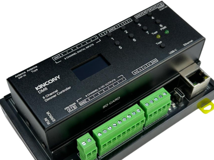
KinCony DM8 ESP32 smart dimmer controller based on ESP32-S3-WROOM-1U (N16R8) wifi chip.
Product introduction video
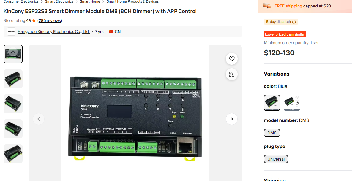
Purchase Link : https://korean.alibaba.com/product-detail/KinCony-ESP32S3-Smart-Dimmer-Module-DM8-1601717914701.html
1) Introduction
Smart lighting systems are no longer limited to simple ON/OFF control. In modern homes, offices, retail stores, hotels, meeting rooms, factories, and building automation systems, lighting brightness often needs to be adjusted according to time, ambient light level, occupancy, energy-saving rules, or user-defined scenes.
One of the most widely used control methods for commercial and industrial lighting is 0–10V dimming. In a 0–10V dimming system, a low-voltage analog signal is sent to a compatible LED driver. The LED driver then adjusts the brightness of the connected light according to the control voltage.
The KinCony DM8 is an ESP32-S3-based 8-channel smart dimmer controller designed for this type of application. It provides 8 channels of DC 0–10V dimming output, 8 dry contact inputs, 4 analog input channels through ADS1115, WIZnet W5500 Ethernet, Wi-Fi, RS485, OLED display, USB-C, SD card support, RTC, and Tuya module support.
From a maker and system integration point of view, the DM8 is especially interesting because it combines three important features in one DIN rail module:
- ESP32-S3 for application logic and IoT control
- WIZnet W5500 Ethernet for stable wired network communication
- 8-channel 0–10V output for professional lighting dimming control
This article explains how to use the KinCony DM8 as an Ethernet-enabled 8-channel smart lighting controller. It covers hardware setup, W5500 Ethernet configuration, 0–10V dimming output, dry contact input, analog input, RS485 communication, ESPHome integration, and Arduino-based TCP control.
Safety Note
The 0–10V output of the DM8 is a low-voltage control signal for compatible LED drivers. It is not a power output for LED strips or lamps. When working with AC mains wiring or LED driver power input wiring, always disconnect power first and follow local electrical safety regulations. Incorrect wiring can damage the controller, LED driver, or lighting fixture.
2) Required Components
| Component | Description |
|---|---|
| KinCony DM8 | ESP32-S3-based 8-channel 0–10V smart dimmer controller |
| 12–24V DC Power Supply | Power supply for the DM8 controller |
| 0–10V Dimmable LED Driver | LED driver with 0–10V dimming input |
| LED Light / Lighting Fixture | Lighting load connected to the LED driver |
| Ethernet Cable | For W5500 wired LAN connection |
| Router / Ethernet Switch | Local network connection |
| USB-C Cable | Firmware upload and serial debugging |
| Dry Contact Switches | Wall switches, relay contacts, or sensor contacts |
| 0–5V Sensor | Sensor for A1/A2 analog voltage input testing |
| 4–20mA Sensor | Industrial sensor for A3/A4 current input testing |
| RS485 Device | Modbus RTU sensor, power meter, PLC, or industrial device |
| Multimeter | Measuring 0–10V output voltage |
| Optional CR1220 Battery | Backup battery for RTC timekeeping |
3) Hardware Setup
The KinCony DM8 is designed as a DIN rail controller, making it suitable for distribution boxes, automation panels, smart lighting cabinets, and building control systems.
The basic hardware setup consists of five parts:
- Supplying DC power to the DM8
- Connecting Ethernet through the W5500 interface
- Wiring 0–10V outputs to LED drivers
- Connecting dry contact inputs
- Connecting sensors or RS485 devices when required
Step 1. Connect DC Power
Connect a 12–24V DC power supply to the DM8 power input terminal.
Before powering the device:
- Check the polarity of the DC input.
- Confirm that the power supply voltage is within the supported range.
- Make sure all field wiring is secure.
- Avoid connecting or disconnecting terminals while the system is powered.
After power is applied, the controller should boot. Depending on the firmware, the OLED display may show network information, device status, or system messages.
Step 2. Connect Ethernet
Connect the RJ45 Ethernet port of the DM8 to a router or Ethernet switch using a standard Ethernet cable.
The DM8 uses a WIZnet W5500 Ethernet controller connected to the ESP32-S3 through SPI. Compared with Wi-Fi, wired Ethernet is often more reliable in control cabinets, commercial buildings, and industrial environments.
Ethernet is especially useful when:
- The controller is installed inside a metal enclosure.
- Wi-Fi signal quality is poor.
- A fixed IP address is required.
- Low-latency and stable communication is important.
- The device must be integrated into a building automation network.
Step 3. Connect 0–10V Outputs to LED Drivers
Each 0–10V output channel of the DM8 should be connected to the dimming input of a compatible LED driver.
A typical LED driver has terminals such as:
- DIM+
- DIM-
- 0–10V+
- 0–10V-
- Vdim+
- Vdim-
Connect each DM8 dimmer channel to the corresponding 0–10V dimming input of the LED driver.
| DM8 Output Voltage | Expected Lighting Behavior |
|---|---|
| 0V | Minimum brightness or nearly OFF |
| 5V | Around 50% brightness |
| 10V | Maximum brightness |
The actual brightness curve depends on the LED driver. Some drivers do not turn completely off at 0V, while others may support full shutoff. Always check the LED driver datasheet.
Step 4. Connect Dry Contact Inputs
The DM8 includes 8 dry contact input channels. These inputs can be used with:
- Wall switches
- Push buttons
- Relay contacts
- Door sensors
- Occupancy sensors
- External automation contacts
A dry contact input should be connected only to a voltage-free contact. Do not directly apply an external voltage unless the input specification explicitly allows it.
Typical use cases include:
- Pressing a wall switch to toggle a lighting channel
- Using a motion sensor relay output to activate a lighting scene
- Connecting a door sensor to trigger corridor lighting
- Using dry contact signals from another automation controller
Step 5. Connect Analog Sensors
The DM8 provides 4 analog input channels through ADS1115.
The input types are typically divided as follows:
| Analog Input | Input Type | Example Sensor |
|---|---|---|
| A1 | 0–5V | Light sensor, pressure sensor, voltage output sensor |
| A2 | 0–5V | Position sensor, environmental sensor |
| A3 | 4–20mA | Industrial pressure sensor |
| A4 | 4–20mA | Level, flow, temperature, or humidity transmitter |
Analog sensors can be used to create closed-loop lighting automation. For example, a 0–5V ambient light sensor can be used to automatically increase or decrease lighting brightness.
Step 6. Connect RS485 Devices
The DM8 includes RS485 support, which can be used for Modbus RTU communication.
RS485 is commonly used with:
- Energy meters
- Temperature and humidity sensors
- Industrial pressure sensors
- PLCs
- HVAC controllers
- Building automation devices
When wiring RS485:
- Connect A to A and B to B.
- If communication fails, try swapping A/B.
- Use twisted-pair cable for longer runs.
- Add termination resistors when required.
- Match baud rate, parity, stop bits, and Modbus slave ID.
4) Interface Explanation
The DM8 combines multiple hardware interfaces around the ESP32-S3. Understanding these interfaces makes it easier to customize firmware, troubleshoot hardware, and integrate the module into real automation systems.
4.1 ESP32-S3 Main Controller
The ESP32-S3 is the main processor of the DM8. It handles:
- Ethernet communication
- Wi-Fi communication
- Web server or API logic
- ESPHome / Home Assistant integration
- I2C peripheral communication
- RS485 communication
- Tuya module communication
- Internal dimmer output control
- Sensor reading and automation rules
The ESP32-S3 is suitable for smart controller applications because it provides enough processing capability for IoT tasks while still being compact and power-efficient.
4.2 WIZnet W5500 Ethernet Interface
The W5500 is a hardware TCP/IP Ethernet controller. It communicates with the ESP32-S3 using SPI.
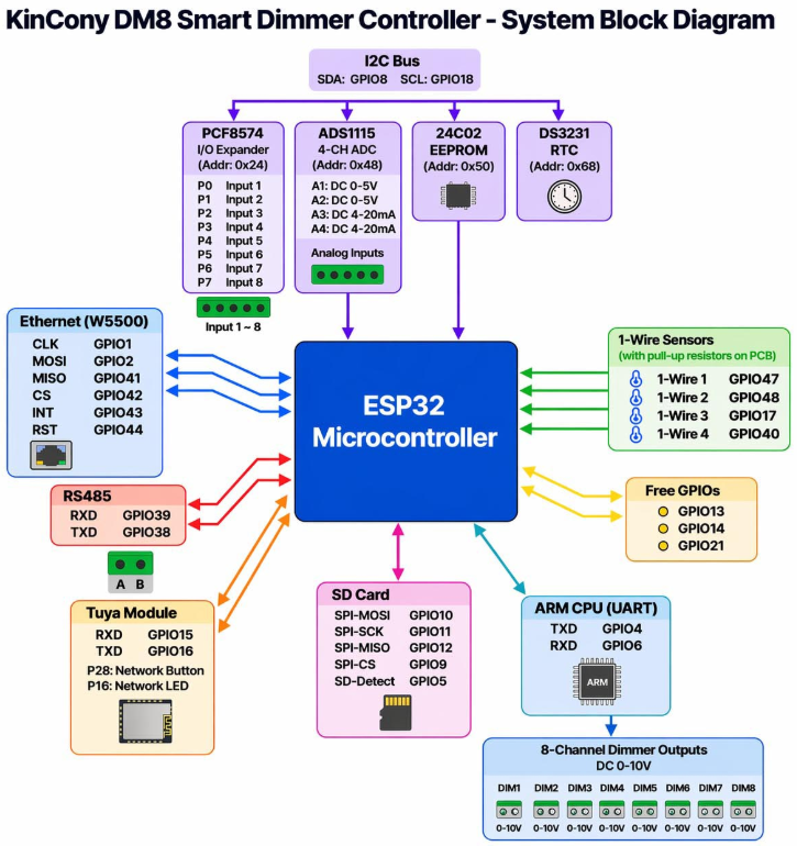
The DM8 W5500 pin assignment is:
| W5500 Function | ESP32-S3 GPIO |
|---|---|
| SPI CLK | GPIO1 |
| SPI MOSI | GPIO2 |
| SPI MISO | GPIO41 |
| SPI CS | GPIO42 |
| Interrupt | GPIO43 |
| Reset | GPIO44 |
The W5500 is valuable in automation projects because it offloads network communication from the MCU and provides stable wired connectivity.
For a smart dimmer controller, Ethernet has several advantages:
- More stable than Wi-Fi in control panels
- Easier to assign static IP addresses
- Better for long-term installation
- Suitable for industrial and commercial systems
- Compatible with MQTT, HTTP, TCP, and local automation servers
4.3 I2C Bus
The DM8 uses an I2C bus for several onboard peripheral chips.
| I2C Function | GPIO / Address | Purpose |
|---|---|---|
| SDA | GPIO8 | I2C data |
| SCL | GPIO18 | I2C clock |
| PCF8574 | 0x24 | 8-channel dry contact input |
| ADS1115 | 0x48 | 4-channel analog input |
| 24C02 EEPROM | 0x50 | Parameter storage |
| DS3231 RTC | 0x68 | Real-time clock |
| SSD1306 OLED | 0x3C | Status display |
Using I2C makes the design expandable. Multiple devices can share the same two signal lines, as long as each device has a unique address.
4.4 0–10V Dimming Output
The main function of the DM8 is 8-channel 0–10V dimming output.
Each channel can be controlled as an analog brightness output. In an ESPHome configuration, each dimming channel can be exposed as a monochromatic light entity in Home Assistant.
A typical brightness mapping is:
| Brightness Percentage | DAC Value | Approx. Output |
|---|---|---|
| 0% | 0 | 0V |
| 25% | 1024 | 2.5V |
| 50% | 2048 | 5V |
| 75% | 3071 | 7.5V |
| 100% | 4095 | 10V |
The DM8 internal dimming control can be handled through Modbus registers.
| Channel | Register Hex | Register Decimal |
|---|---|---|
| CH1 | 0x0FA0 | 4000 |
| CH2 | 0x0FA1 | 4001 |
| CH3 | 0x0FA2 | 4002 |
| CH4 | 0x0FA3 | 4003 |
| CH5 | 0x0FA4 | 4004 |
| CH6 | 0x0FA5 | 4005 |
| CH7 | 0x0FA6 | 4006 |
| CH8 | 0x0FA7 | 4007 |
4.5 RS485 Interface
The ESP32-side RS485 interface uses:
| RS485 Function | ESP32-S3 GPIO |
|---|---|
| RXD | GPIO38 |
| TXD | GPIO39 |
RS485 is useful when the DM8 needs to communicate with external Modbus RTU devices.
Example applications:
- Reading energy meter data
- Receiving temperature and humidity values
- Connecting to PLC systems
- Controlling HVAC equipment
- Building a lighting controller with external sensor feedback
4.6 SD Card Interface
The DM8 includes an SPI SD card interface.
| SD Card Function | ESP32-S3 GPIO |
|---|---|
| MOSI | GPIO10 |
| SCK | GPIO11 |
| MISO | GPIO12 |
| CS | GPIO9 |
| Detect | GPIO5 |
The SD card can be used for:
- Lighting event logs
- Sensor data logging
- Error logs
- Schedule files
- Offline configuration backup
4.7 Tuya UART Interface
The DM8 also supports a Tuya module interface.
| Tuya Function | ESP32-S3 GPIO |
|---|---|
| RXD | GPIO15 |
| TXD | GPIO16 |
This enables integration with Tuya-based smart home systems when the correct firmware is used.
5) Wiring Table
5.1 External Wiring Table
| DM8 Terminal / Interface | Connect To | Description |
|---|---|---|
| DC Power Input | 12–24V DC power supply | Main power input |
| RJ45 Ethernet | Router or Ethernet switch | W5500 wired LAN connection |
| 0–10V CH1 | LED Driver 1 DIM input | Brightness control for light zone 1 |
| 0–10V CH2 | LED Driver 2 DIM input | Brightness control for light zone 2 |
| 0–10V CH3 | LED Driver 3 DIM input | Brightness control for light zone 3 |
| 0–10V CH4 | LED Driver 4 DIM input | Brightness control for light zone 4 |
| 0–10V CH5 | LED Driver 5 DIM input | Brightness control for light zone 5 |
| 0–10V CH6 | LED Driver 6 DIM input | Brightness control for light zone 6 |
| 0–10V CH7 | LED Driver 7 DIM input | Brightness control for light zone 7 |
| 0–10V CH8 | LED Driver 8 DIM input | Brightness control for light zone 8 |
| DI1–DI8 | Dry contact switches | Wall switch or relay input |
| A1, A2 | 0–5V sensors | Analog voltage sensors |
| A3, A4 | 4–20mA sensors | Industrial current-loop sensors |
| RS485 A/B | Modbus RTU device | Industrial communication |
| USB-C | PC | Firmware upload and serial debugging |
| SD Card Slot | MicroSD card | Data logging |
| RTC Battery Socket | CR1220 battery | RTC backup power |
5.2 ESP32-S3 Internal Pin Table
| Function | GPIO / Address | Description |
|---|---|---|
| I2C SDA | GPIO8 | I2C data line |
| I2C SCL | GPIO18 | I2C clock line |
| PCF8574 | 0x24 | Dry contact input expander |
| ADS1115 | 0x48 | 16-bit ADC |
| EEPROM 24C02 | 0x50 | Configuration storage |
| DS3231 RTC | 0x68 | Real-time clock |
| OLED SSD1306 | 0x3C | Display module |
| W5500 CLK | GPIO1 | Ethernet SPI clock |
| W5500 MOSI | GPIO2 | Ethernet SPI MOSI |
| W5500 MISO | GPIO41 | Ethernet SPI MISO |
| W5500 CS | GPIO42 | Ethernet chip select |
| W5500 INT | GPIO43 | Ethernet interrupt |
| W5500 RST | GPIO44 | Ethernet reset |
| RS485 RXD | GPIO38 | ESP32 RS485 receive |
| RS485 TXD | GPIO39 | ESP32 RS485 transmit |
| Tuya RXD | GPIO15 | Tuya UART receive |
| Tuya TXD | GPIO16 | Tuya UART transmit |
| SD MOSI | GPIO10 | SD card SPI MOSI |
| SD SCK | GPIO11 | SD card SPI clock |
| SD MISO | GPIO12 | SD card SPI MISO |
| SD CS | GPIO9 | SD card chip select |
| SD Detect | GPIO5 | SD card detection |
| Internal DAC RX | GPIO4 | ESP32 receives from internal controller |
| Internal DAC TX | GPIO6 | ESP32 transmits to internal controller |
6) Software Environment Setup
The DM8 can be used in several different ways depending on the project goal.
6.1 Option 1: KCS v3 Firmware
KCS v3 is KinCony’s ready-to-use firmware platform. It is useful when users want a web-based configuration interface without writing code.
With KCS v3, the DM8 can be used with:
- Web UI
- MQTT
- TCP commands
- HTTP control
- RS485 Modbus
- Tuya app
- Home Assistant MQTT auto discovery
- IFTTT
- Loxone integration
This is the fastest option for users who want to deploy the controller quickly.
Typical setup process:
- Download the correct KCS v3 firmware for the ESP32-S3 DM8 board.
- Connect the DM8 to the PC through USB-C.
- Flash the firmware using the recommended download tool.
- Connect Ethernet or use Wi-Fi AP mode.
- Open the device web interface.
- Configure network, MQTT, I/O, dimmer channels, and automation rules.
- Change the default password before final installation.
6.2 Option 2: ESPHome
ESPHome is a good choice for Home Assistant users.
With ESPHome, the DM8 can be configured through YAML. Each 0–10V output channel can appear in Home Assistant as a light entity. Dry contact inputs can appear as binary sensors. Analog inputs can appear as sensor entities.
ESPHome is recommended when:
- Home Assistant is the main automation platform.
- The user wants simple YAML-based configuration.
- OTA updates are required.
- Lighting channels should be controlled from Home Assistant dashboards.
- Inputs and sensors should be used in Home Assistant automations.
6.3 Option 3: Arduino IDE
Arduino IDE is suitable when custom firmware is required.
Use Arduino IDE when the project needs:
- A custom TCP server
- A custom HTTP API
- Modbus gateway logic
- Local automation independent from Home Assistant
- Sensor-based dimming algorithms
- SD card logging
- Integration with third-party systems
Recommended Arduino setup:
| Item | Recommended Setting |
|---|---|
| IDE | Arduino IDE 2.x |
| Board Package | ESP32 by Espressif |
| Board | ESP32S3 Dev Module or ESP32-S3-DevKitC-1 |
| USB CDC On Boot | Enabled |
| Upload Port | USB serial port |
| Libraries | Ethernet, SPI, Wire, ADS1115, PCF8574, RTC libraries |
7) Full Code Examples
This section provides two practical examples:
- ESPHome YAML for Home Assistant integration
- Arduino TCP server for Ethernet-based 0–10V dimming control
Example 1. ESPHome YAML: 8-Channel 0–10V Dimmer with Ethernet
This ESPHome example exposes the DM8 as an 8-channel lighting controller in Home Assistant.
Each dimmer channel appears as a monochromatic light entity. When the brightness slider is changed in Home Assistant, ESPHome writes the corresponding value to the internal dimming register.
esphome:
  name: dm8
  friendly_name: KinCony DM8 8CH Dimmer

esp32:
  board: esp32-s3-devkitc-1
  framework:
    type: arduino

logger:

api:

ota:
  - platform: esphome

# WIZnet W5500 Ethernet
ethernet:
  type: W5500
  clk_pin: GPIO1
  mosi_pin: GPIO2
  miso_pin: GPIO41
  cs_pin: GPIO42
  interrupt_pin: GPIO43
  reset_pin: GPIO44

# UART for external RS485 and internal dimmer control
uart:
  - id: rs485_uart
    baud_rate: 9600
    tx_pin: GPIO39
    rx_pin: GPIO38

  - id: dac_uart
    baud_rate: 115200
    tx_pin: GPIO6
    rx_pin: GPIO4
    stop_bits: 1
    data_bits: 8
    parity: NONE

modbus:
  uart_id: dac_uart

modbus_controller:
  - id: dm8_dac
    address: 1
    update_interval: 5s

# I2C bus
i2c:
  sda: GPIO8
  scl: GPIO18
  scan: true
  frequency: 400kHz

# OLED display
font:
  - file: "gfonts://Roboto"
    id: roboto_15
    size: 15

text_sensor:
  - platform: ethernet_info
    ip_address:
      name: "DM8 Ethernet IP"
      id: dm8_eth_ip
    mac_address:
      name: "DM8 Ethernet MAC"

display:
  - platform: ssd1306_i2c
    model: "SSD1306 128x64"
    address: 0x3C
    lambda: |-
      it.printf(0, 0, id(roboto_15), "KinCony DM8");
      it.printf(0, 20, id(roboto_15), "IP:");
      it.printf(0, 40, id(roboto_15), "%s", id(dm8_eth_ip).state.c_str());

# 0-10V DAC outputs
# Brightness 0.0-1.0 is mapped to DAC value 0-4095
output:
  - platform: modbus_controller
    id: dac_ch1
    address: 0x0FA0
    value_type: U_WORD
    write_lambda: |-
      return (uint16_t) round(x * 4095.0);

  - platform: modbus_controller
    id: dac_ch2
    address: 0x0FA1
    value_type: U_WORD
    write_lambda: |-
      return (uint16_t) round(x * 4095.0);

  - platform: modbus_controller
    id: dac_ch3
    address: 0x0FA2
    value_type: U_WORD
    write_lambda: |-
      return (uint16_t) round(x * 4095.0);

  - platform: modbus_controller
    id: dac_ch4
    address: 0x0FA3
    value_type: U_WORD
    write_lambda: |-
      return (uint16_t) round(x * 4095.0);

  - platform: modbus_controller
    id: dac_ch5
    address: 0x0FA4
    value_type: U_WORD
    write_lambda: |-
      return (uint16_t) round(x * 4095.0);

  - platform: modbus_controller
    id: dac_ch6
    address: 0x0FA5
    value_type: U_WORD
    write_lambda: |-
      return (uint16_t) round(x * 4095.0);

  - platform: modbus_controller
    id: dac_ch7
    address: 0x0FA6
    value_type: U_WORD
    write_lambda: |-
      return (uint16_t) round(x * 4095.0);

  - platform: modbus_controller
    id: dac_ch8
    address: 0x0FA7
    value_type: U_WORD
    write_lambda: |-
      return (uint16_t) round(x * 4095.0);

light:
  - platform: monochromatic
    name: "DM8 Dimmer CH1"
    output: dac_ch1
    default_transition_length: 0s

  - platform: monochromatic
    name: "DM8 Dimmer CH2"
    output: dac_ch2
    default_transition_length: 0s

  - platform: monochromatic
    name: "DM8 Dimmer CH3"
    output: dac_ch3
    default_transition_length: 0s

  - platform: monochromatic
    name: "DM8 Dimmer CH4"
    output: dac_ch4
    default_transition_length: 0s

  - platform: monochromatic
    name: "DM8 Dimmer CH5"
    output: dac_ch5
    default_transition_length: 0s

  - platform: monochromatic
    name: "DM8 Dimmer CH6"
    output: dac_ch6
    default_transition_length: 0s

  - platform: monochromatic
    name: "DM8 Dimmer CH7"
    output: dac_ch7
    default_transition_length: 0s

  - platform: monochromatic
    name: "DM8 Dimmer CH8"
    output: dac_ch8
    default_transition_length: 0s

# Dry contact input expander
pcf8574:
  - id: pcf8574_inputs
    address: 0x24

binary_sensor:
  - platform: gpio
    name: "DM8 Input 1"
    pin:
      pcf8574: pcf8574_inputs
      number: 0
      mode: INPUT
      inverted: true

  - platform: gpio
    name: "DM8 Input 2"
    pin:
      pcf8574: pcf8574_inputs
      number: 1
      mode: INPUT
      inverted: true

  - platform: gpio
    name: "DM8 Input 3"
    pin:
      pcf8574: pcf8574_inputs
      number: 2
      mode: INPUT
      inverted: true

  - platform: gpio
    name: "DM8 Input 4"
    pin:
      pcf8574: pcf8574_inputs
      number: 3
      mode: INPUT
      inverted: true

  - platform: gpio
    name: "DM8 Input 5"
    pin:
      pcf8574: pcf8574_inputs
      number: 4
      mode: INPUT
      inverted: true

  - platform: gpio
    name: "DM8 Input 6"
    pin:
      pcf8574: pcf8574_inputs
      number: 5
      mode: INPUT
      inverted: true

  - platform: gpio
    name: "DM8 Input 7"
    pin:
      pcf8574: pcf8574_inputs
      number: 6
      mode: INPUT
      inverted: true

  - platform: gpio
    name: "DM8 Input 8"
    pin:
      pcf8574: pcf8574_inputs
      number: 7
      mode: INPUT
      inverted: true

# ADS1115 analog inputs
ads1115:
  - address: 0x48

sensor:
  - platform: ads1115
    name: "DM8 Analog A1 0-5V"
    multiplexer: A0_GND
    gain: 6.144
    resolution: 16_BITS
    update_interval: 5s

  - platform: ads1115
    name: "DM8 Analog A2 0-5V"
    multiplexer: A1_GND
    gain: 6.144
    resolution: 16_BITS
    update_interval: 5s

  - platform: ads1115
    name: "DM8 Analog A3 4-20mA"
    multiplexer: A2_GND
    gain: 6.144
    resolution: 16_BITS
    update_interval: 5s

  - platform: ads1115
    name: "DM8 Analog A4 4-20mA"
    multiplexer: A3_GND
    gain: 6.144
    resolution: 16_BITS
    update_interval: 5s

web_server:
  port: 80
Example 2. Arduino IDE: W5500 TCP Server for 8-Channel 0–10V Control
This example turns the DM8 into a TCP-based Ethernet dimmer controller.
A PC, server, PLC gateway, or Node-RED flow can connect to the DM8 over TCP and send simple commands.
Command format:
SET,<channel>,<percent>Examples:
SET,1,50
SET,8,100
SET,3,0
Command parameters:
| Parameter | Description |
|---|---|
| channel | 1 to 8 |
| percent | Brightness percentage from 0 to 100 |
| output value | Converted internally to 0–4095 |
| register range | CH1 = 4000, CH8 = 4007 |
#include <Arduino.h>
#include <SPI.h>
#include <Ethernet.h>

// =========================
// DM8 W5500 pin definition
// =========================
#define W5500_CLK_PIN   1
#define W5500_MOSI_PIN  2
#define W5500_MISO_PIN  41
#define W5500_CS_PIN    42
#define W5500_INT_PIN   43
#define W5500_RST_PIN   44

// =========================
// DM8 internal DAC UART
// ESP32 RX <- internal controller TX : GPIO4
// ESP32 TX -> internal controller RX : GPIO6
// =========================
#define DAC_RX_PIN 4
#define DAC_TX_PIN 6

HardwareSerial dacSerial(1);

// Change this MAC address if multiple boards are used on the same network.
byte mac[] = { 0x02, 0x57, 0x49, 0x5A, 0x44, 0x38 };

// Static IP example. Change it according to your LAN.
IPAddress ip(192, 168, 1, 88);
IPAddress dns(192, 168, 1, 1);
IPAddress gateway(192, 168, 1, 1);
IPAddress subnet(255, 255, 255, 0);

EthernetServer server(4196);

// -------------------------
// Modbus RTU CRC16
// -------------------------
uint16_t modbusCRC16(const uint8_t *data, size_t length) {
  uint16_t crc = 0xFFFF;

  for (size_t i = 0; i < length; i++) {
    crc ^= data[i];

    for (uint8_t bit = 0; bit < 8; bit++) {
      if (crc & 0x0001) {
        crc = (crc >> 1) ^ 0xA001;
      } else {
        crc >>= 1;
      }
    }
  }

  return crc;
}

// -------------------------
// Write one DAC register
// Slave ID: 1
// Function: 0x06 Write Single Register
// Register: 4000-4007
// Value: 0-4095
// -------------------------
void writeDimmerRegister(uint8_t channel, uint16_t value) {
  if (channel < 1 || channel > 8) return;
  if (value > 4095) value = 4095;

  uint16_t reg = 4000 + (channel - 1);

  uint8_t frame[8];
  frame[0] = 0x01;                 // Modbus slave address
  frame[1] = 0x06;                 // Write single register
  frame[2] = highByte(reg);
  frame[3] = lowByte(reg);
  frame[4] = highByte(value);
  frame[5] = lowByte(value);

  uint16_t crc = modbusCRC16(frame, 6);
  frame[6] = lowByte(crc);
  frame[7] = highByte(crc);

  dacSerial.write(frame, sizeof(frame));
  dacSerial.flush();

  Serial.printf("CH%u -> register %u, value %u\r\n", channel, reg, value);
}

// -------------------------
// Parse command: SET,ch,percent
// Example: SET,1,75
// -------------------------
String handleCommand(String cmd) {
  cmd.trim();
  cmd.toUpperCase();

  if (!cmd.startsWith("SET,")) {
    return "ERR,USE SET,<CH 1-8>,<PERCENT 0-100>\r\n";
  }

  int firstComma = cmd.indexOf(',');
  int secondComma = cmd.indexOf(',', firstComma + 1);

  if (firstComma < 0 || secondComma < 0) {
    return "ERR,BAD_FORMAT\r\n";
  }

  int channel = cmd.substring(firstComma + 1, secondComma).toInt();
  int percent = cmd.substring(secondComma + 1).toInt();

  if (channel < 1 || channel > 8) {
    return "ERR,CHANNEL_RANGE\r\n";
  }

  if (percent < 0) percent = 0;
  if (percent > 100) percent = 100;

  uint16_t dacValue = map(percent, 0, 100, 0, 4095);
  writeDimmerRegister((uint8_t)channel, dacValue);

  String reply = "OK,CH";
  reply += channel;
  reply += ",";
  reply += percent;
  reply += "%,DAC=";
  reply += dacValue;
  reply += "\r\n";

  return reply;
}

void resetW5500() {
  pinMode(W5500_RST_PIN, OUTPUT);
  digitalWrite(W5500_RST_PIN, LOW);
  delay(100);
  digitalWrite(W5500_RST_PIN, HIGH);
  delay(300);
}

void setup() {
  Serial.begin(115200);
  delay(1000);

  Serial.println();
  Serial.println("KinCony DM8 - W5500 TCP 0-10V Dimmer Controller");

  // Internal DAC UART
  dacSerial.begin(115200, SERIAL_8N1, DAC_RX_PIN, DAC_TX_PIN);

  // W5500 Ethernet
  pinMode(W5500_INT_PIN, INPUT);
  resetW5500();

  SPI.begin(W5500_CLK_PIN, W5500_MISO_PIN, W5500_MOSI_PIN);
  Ethernet.init(W5500_CS_PIN);
  Ethernet.begin(mac, ip, dns, gateway, subnet);

  delay(500);

  Serial.print("Ethernet IP: ");
  Serial.println(Ethernet.localIP());

  server.begin();
  Serial.println("TCP server started on port 4196");

  // Safe startup: set all dimmer channels to 0%
  for (uint8_t ch = 1; ch <= 8; ch++) {
    writeDimmerRegister(ch, 0);
    delay(50);
  }
}

void loop() {
  EthernetClient client = server.available();

  if (!client) {
    return;
  }

  Serial.println("Client connected");
  client.println("KinCony DM8 TCP Dimmer");
  client.println("Command: SET,<CH 1-8>,<PERCENT 0-100>");
  client.println("Example: SET,1,50");

  String buffer = "";

  while (client.connected()) {
    while (client.available()) {
      char c = client.read();

      if (c == '\n' || c == '\r') {
        if (buffer.length() > 0) {
          String reply = handleCommand(buffer);
          client.print(reply);
          buffer = "";
        }
      } else {
        buffer += c;
        if (buffer.length() > 64) {
          buffer = "";
          client.println("ERR,COMMAND_TOO_LONG");
        }
      }
    }
  }

  client.stop();
  Serial.println("Client disconnected");
}
8) Testing Steps
Test 1. Power-On Check
Apply 12–24V DC power to the DM8.
Check the following:
- Power LED or status indicator is active.
- OLED display turns on if supported by the firmware.
- No component becomes unusually hot.
- USB serial output is available when connected to a PC.
Test 2. Ethernet Connection Test
Connect the DM8 to the local network using Ethernet.
For the Arduino example above, the static IP address is:
192.168.1.88From a PC on the same network, run:
ping 192.168.1.88A successful ping means the W5500 Ethernet interface is working.
When using a different LAN subnet, change the IP address in the Arduino code before uploading.
Test 3. TCP Command Test
Use a TCP client such as netcat.
nc 192.168.1.88 4196Send commands:
SET,1,50
SET,2,100
SET,1,0
Expected responses:
OK,CH1,50%,DAC=2047
OK,CH2,100%,DAC=4095
OK,CH1,0%,DAC=0
The exact DAC value may differ slightly depending on integer rounding.
Test 4. 0–10V Voltage Output Test
Use a multimeter to measure the output voltage of each channel.
| TCP Command | Expected CH1 Output |
|---|---|
| SET,1,0 | About 0V |
| SET,1,25 | About 2.5V |
| SET,1,50 | About 5V |
| SET,1,75 | About 7.5V |
| SET,1,100 | About 10V |
Test the voltage before connecting the LED driver. This makes troubleshooting easier and reduces the risk of damaging external equipment.
Test 5. LED Driver Dimming Test
After confirming the 0–10V output with a multimeter, connect the output to a compatible LED driver.
Then send commands again:
SET,1,10
SET,1,50
SET,1,100
The brightness of the connected light should change gradually.
If the light does not turn completely off at 0%, check the LED driver specification. Some 0–10V drivers require a separate relay or power control circuit for complete shutoff.
Test 6. ESPHome and Home Assistant Test
After uploading the ESPHome YAML:
- Open Home Assistant.
- Go to the ESPHome device page.
- Confirm that the DM8 is online.
- Check that 8 dimmer light entities are created.
- Move each brightness slider.
- Measure the corresponding 0–10V output.
- Confirm that the LED driver follows the brightness value.
This test verifies both Ethernet communication and dimmer control.
Test 7. Dry Contact Input Test
Connect a push button or wall switch to one of the dry contact inputs.
In Home Assistant or serial logs, check whether the input state changes when the switch is pressed.
If the logic appears reversed, change the inverted setting in ESPHome.
Test 8. Analog Input Test
Connect a known analog signal to A1 or A2.
For example:
| Input Voltage | Expected Result |
|---|---|
| 0V | Low ADC value |
| 2.5V | Mid-scale value |
| 5V | High ADC value |
For A3/A4, use a proper 4–20mA sensor or current source. Do not apply a voltage signal directly to a current-loop input unless the hardware design supports it.
9) Troubleshooting
Problem 1. Ethernet IP Is Not Available
Possible causes:
- Wrong W5500 SPI pin configuration
- Ethernet cable problem
- Router or switch port issue
- Static IP address outside the LAN subnet
- MAC address conflict
- W5500 reset pin not controlled correctly
Solutions:
- Check that W5500 pins are configured as GPIO1, GPIO2, GPIO41, GPIO42, GPIO43, and GPIO44.
- Try another Ethernet cable.
- Try another router or switch port.
- Change the static IP to match your network.
- Use a unique MAC address for each controller.
- Check serial monitor output for Ethernet initialization messages.
Problem 2. 0–10V Output Does Not Change
Possible causes:
- Wrong internal UART pin configuration
- Wrong Modbus register address
- Incorrect LED driver wiring
- LED driver does not support 0–10V dimming
- Output channel is not initialized
- Firmware is not sending the correct command
Solutions:
- Use GPIO4 as RX and GPIO6 as TX for the internal DAC UART.
- Use register 4000 for CH1 and 4007 for CH8.
- Test the output with a multimeter before connecting the LED driver.
- Confirm the LED driver’s DIM+ and DIM- polarity.
- Check whether the driver requires a separate enable signal.
Problem 3. Dry Contact Input Works in Reverse
Some dry contact input circuits are active-low.
For ESPHome, change:
inverted: trueto:
inverted: falseor the opposite, depending on the observed behavior.
Problem 4. ADS1115 Analog Value Is Incorrect
Possible causes:
- Wrong input channel selected
- Wrong input type used
- Sensor ground is not connected correctly
- Input voltage exceeds the supported range
- 4–20mA sensor wiring is incorrect
- I2C address is wrong
Solutions:
- Use A1/A2 for 0–5V signals.
- Use A3/A4 for 4–20mA signals.
- Check the common ground for voltage-output sensors.
- Confirm ADS1115 address 0x48.
- Use a known test voltage first.
- Verify the sensor wiring diagram.
Problem 5. RS485 Communication Fails
Possible causes:
- A/B lines are reversed
- Baud rate mismatch
- Wrong Modbus slave ID
- Parity or stop bit mismatch
- Missing termination resistor
- Long cable without proper shielding
Solutions:
- Swap A and B lines.
- Start with 9600 baud, 8N1.
- Confirm the slave ID of the Modbus device.
- Check parity and stop bit settings.
- Add termination if the cable is long.
- Use twisted-pair cable for RS485.
Problem 6. Home Assistant Does Not Detect the Device
Possible causes:
- ESPHome API not enabled
- Ethernet network issue
- Firewall or VLAN isolation
- Wrong board configuration
- OTA upload failed
Solutions:
- Confirm that
api:is enabled in the YAML file. - Check whether the DM8 receives an IP address.
- Make sure Home Assistant and DM8 are on the same network.
- Check ESPHome logs.
- Use USB upload first, then switch to OTA updates.
10) Use Cases & Market Potential
Smart Home Lighting Control
The DM8 can be used as a central lighting controller for a smart home.
Example configuration:
| Channel | Lighting Area |
|---|---|
| CH1 | Living room main light |
| CH2 | Living room indirect light |
| CH3 | Kitchen light |
| CH4 | Dining light |
| CH5 | Bedroom light |
| CH6 | Hallway light |
| CH7 | Bathroom light |
| CH8 | Outdoor light |
With Home Assistant, users can create scenes such as:
- Movie mode
- Dinner mode
- Night mode
- Wake-up lighting
- Away mode
- Energy-saving mode
Commercial Lighting
In commercial spaces, lighting control is directly related to user experience and energy cost.
The DM8 can be used in:
- Meeting rooms
- Restaurants
- Cafes
- Hotels
- Retail shops
- Exhibition spaces
- Office floors
A single DM8 can manage up to 8 lighting zones, making it suitable for small and medium-size lighting control systems.
Building Automation
Because the DM8 supports Ethernet, RS485, MQTT, HTTP, and TCP-based control depending on firmware, it can be integrated into building automation systems.
Possible integrations include:
- Home Assistant
- Node-RED
- MQTT broker
- PLC gateway
- BMS software
- Custom TCP server
- Web dashboard
- Modbus RTU devices
Ethernet is especially important in building automation because fixed wiring is usually preferred over wireless control.
Industrial Lighting and Sensor-Based Control
The DM8 can also be used in industrial environments where lighting must respond to sensor data.
Example applications:
- Factory workbench lighting
- Warehouse aisle lighting
- Machine area lighting
- Sensor-based daylight compensation
- Scheduled lighting control
- Energy-saving lighting automation
The 4–20mA input channels are suitable for industrial sensors, while RS485 can be used to communicate with power meters, PLCs, and environmental sensors.
Energy Saving Automation
Lighting is one of the easiest systems to optimize for energy saving.
The DM8 can reduce energy consumption by combining:
- Time schedules
- Occupancy detection
- Ambient light sensing
- Zone-based dimming
- Manual override switches
- Network-based control policies
For example, a corridor can run at 20% brightness when empty and increase to 80% when motion is detected. Office lighting can automatically dim when enough daylight is available.
11) Module/Chip Technical Overview
KinCony DM8
The KinCony DM8 is an ESP32-S3-based smart dimmer module designed for 0–10V lighting control.
Main features include:
- ESP32-S3-WROOM-1U module
- 8-channel 0–10V dimming output
- 8-channel dry contact input
- 4-channel analog input
- WIZnet W5500 Ethernet
- Wi-Fi
- RS485
- USB-C
- OLED display
- SD card interface
- DS3231 RTC
- Tuya module support
- DIN rail enclosure
This combination makes the DM8 suitable for both maker projects and practical automation installations.
ESP32-S3-WROOM-1U
The ESP32-S3-WROOM-1U is a Wi-Fi and Bluetooth LE MCU module based on the ESP32-S3.
In the DM8, the ESP32-S3 is responsible for:
- Running application firmware
- Managing Ethernet communication
- Reading sensor inputs
- Sending dimmer output commands
- Handling local automation logic
- Communicating with Home Assistant or cloud platforms
Its combination of wireless connectivity, GPIO capability, and embedded processing makes it suitable for smart control systems.
WIZnet W5500
The WIZnet W5500 is a hardware TCP/IP Ethernet controller.
It supports SPI communication with the host MCU and provides wired Ethernet connectivity. In the DM8, the W5500 enables stable LAN-based control, which is important for lighting automation and building control systems.
Key advantages of using W5500:
- Reliable wired communication
- Hardware TCP/IP processing
- Reduced network stack burden on the MCU
- Good compatibility with embedded systems
- Suitable for local TCP, HTTP, MQTT, and control applications
For smart dimming systems, Ethernet is often preferred when the controller is installed permanently.
ADS1115
The ADS1115 is a 16-bit ADC with I2C communication.
In the DM8, it is used to read the analog input channels. This allows the controller to work with sensors such as:
- Ambient light sensors
- Pressure sensors
- Level sensors
- Temperature transmitters
- 4–20mA industrial sensors
Analog input is important because it allows lighting control to become responsive to real-world conditions.
PCF8574
The PCF8574 is an I2C I/O expander.
In the DM8, it expands the ESP32-S3 input capability and is used for dry contact input reading.
This is useful because the ESP32-S3 can monitor multiple switch or contact inputs without using many direct GPIO pins.
DS3231 RTC
The DS3231 is a real-time clock module.
It allows the DM8 to keep time even when network time is unavailable. With a backup battery, it can continue maintaining time when the main power is disconnected.
RTC support is useful for:
- Scheduled lighting scenes
- Offline automation
- Time-based dimming
- Daily or weekly control rules
- Event logging with timestamps
SSD1306 OLED
The SSD1306 OLED display is used to show basic system information.
Typical displayed information may include:
- Ethernet IP address
- Wi-Fi IP address
- Device status
- Tuya connection status
- Firmware status
- Debug information
A local display is helpful during installation because the installer can confirm the network status without connecting to a serial monitor.
12) Conclusion
The KinCony DM8 is a practical and powerful platform for building a professional 8-channel 0–10V smart lighting controller. By combining ESP32-S3 processing, WIZnet W5500 Ethernet, RS485, analog input, dry contact input, RTC, OLED, and multiple firmware options, it provides much more than simple dimming output.
For maker projects, the DM8 is attractive because it can be used in several ways. Beginners can start with KCS v3 firmware or ESPHome. Advanced users can write custom Arduino or ESP-IDF firmware to implement TCP control, MQTT integration, Modbus logic, sensor-based dimming, and local automation rules.
The W5500 Ethernet interface is especially valuable for reliable installations. In smart homes, offices, factories, and commercial buildings, wired Ethernet gives the controller a stable communication path and makes it suitable for long-term deployment.
With the DM8, makers and integrators can build systems such as:
- Home Assistant-based 8-channel lighting panels
- Ethernet-based 0–10V commercial lighting controllers
- Sensor-driven daylight compensation systems
- RS485-connected industrial lighting controllers
- Scheduled lighting automation systems
- MQTT/TCP/HTTP-enabled building control nodes
Overall, the KinCony DM8 is a strong example of how ESP32-S3 and WIZnet W5500 can be combined to create a reliable, network-connected smart lighting controller for real-world automation projects.