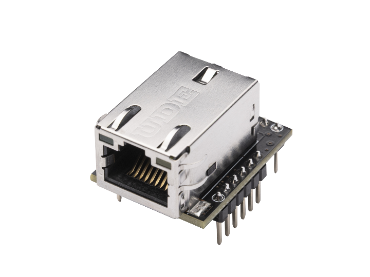
W6300 QSPI Hardware Design Guide
Design tips and real-world insights for stable W6300 QSPI operation and signal integrity optimization.

Practical Tips and Insights for Ensuring Signal Integrity and Stable Operation
The W6300 from WIZnet is a high-performance Ethernet controller that supports high-speed QSPI (Quad SPI) interface, designed for embedded applications where fast data transfer is critical. However, due to the nature of high-speed signals, careful hardware design is essential. In particular, signal integrity issues can arise when the distance between the MCU and the W6300 increases, potentially leading to unstable communication or even total communication failure.
This post shares key hardware design tips and lessons learned from both user feedback and WIZnet’s in-house experience to help ensure stable operation of the W6300 in QSPI mode.
1. Real-World Issues Observed in User Setups
📌 Single SPI mode: Stable operation even at 50 MHz clock speed
⚠️ Dual mode: Works only at ≤ 5 MHz; unstable above that
❌ Quad mode: Fails to operate at all
💡 Setup details:
MCU (STM32) and W6300 connected via pin headers
Approximate distance: 100mm
These cases clearly show that distance and signal topology can seriously affect QSPI operation.
2. Recommendations for Reliable QSPI Design
✅ Keep signal lines short
Aim for a distance less than 2 cm between the MCU and W6300 whenever possible.
🔍 Example: WIZnet's reference boards like W6300-EVB-Pico and W6300-EVB-Pico2 operate reliably up to 80 MHz QSPI with a 2 cm interconnect.
✅ Match data line lengths
QSPI communication is highly sensitive to timing skew across the data lines.
Use length matching techniques to minimize skew between DQ lines.
Consistent trace routing is key.
✅ Add series resistors
To reduce signal reflection and ringing, place 33–49Ω resistors in series on high-speed lines (e.g., CLK, DQ0–DQ3).
🔍 Example: In WIZ630io module designs, series resistors allowed stable communication at 50 Mbps over a 10 cm cable.
✅ Check pull-up / pull-down resistor configurations
Unlike the W5500, the W6300 relies heavily on proper QSPI signal levels.
Consider pull-up resistors on /CS, /RST, and /INT
Consider pull-down on CLK if needed
Always review official reference schematics before implementation
✅ Use termination resistors when needed
If you're experiencing signal reflection:
Try placing a 50Ω termination resistor at the receiving end of signal lines.
Especially useful for longer traces or cables.
3. Debug Checklist for QSPI Issues
| Checkpoint | What to Inspect |
|---|---|
| Trace length | Is the MCU ↔ W6300 distance > 100mm? |
| Clock speed | Is the QSPI speed too high (e.g., 50 MHz+)? |
| Series resistors | Missing or inconsistently placed? |
| Skew control | Are DQ lines unmatched in length? |
| Power/Grounding | Is the GND routing poor or decoupling missing? |
4. Conclusion & Design Alternatives
While the W6300 delivers high-speed QSPI communication, it requires precise PCB layout and thoughtful signal management.
To unlock the full performance of the W6300:
Prioritize signal integrity
Follow proven design guidelines
Use reference boards and schematics when in doubt
A properly designed system ensures you’ll get the most out of W6300’s powerful features, without running into the frustrating pitfalls of high-speed digital design.
👉 For reference design details, please visit: https://docs.wiznet.io/Product/ioModule/wiz630io
