Delving into Ethernet Board Design: Optimizing PCB with W5500 Chip
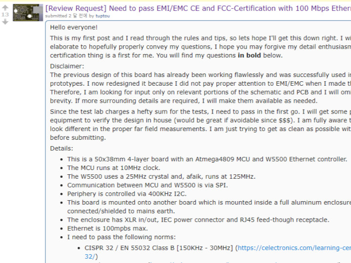
Reddit [Review Request] Need to pass EMI/EMC CE and FCC-Certification with 100 Mbps Ethernet Board (used W5500)

reddit : Circuit/Layout preview please W5500 Ethernet board
https://old.reddit.com/r/PrintedCircuitBoard/comments/uqzwe2/circuitlayout_preview_please_w5500_ethernet_board/
Introduction:
Greetings, tech enthusiasts!
In my inaugural post, I aim to delve into the intricacies of my latest venture into certification, seeking insights and guidance from the knowledgeable community. This certification journey is uncharted territory for me, making it both exciting and challenging. Join me in exploring the nuances of EMI/EMC considerations in my 50x38mm 4-layer board design, featuring an Atmega4809 MCU and a W5500 Ethernet controller.
Certification Objectives and Context:
Before we plunge into the specifics, a quick disclaimer: the previous design of my board was a triumph, functioning seamlessly in various prototypes. However, a lack of attention to EMI/EMC prompted a redesign. With hefty test lab charges, passing the certification in the first attempt is imperative. To achieve this, I've invested in pre-compliance test equipment to meticulously evaluate my design before submitting it for testing.
Board Specifications:
The 4-layer stackup comprises signal, ground, power, and signal layers. Ground pours on both signal layers, via stitching, and a separated analog power section beneath the W5500 contribute to the design's complexity. The enclosure, housing the board, is a fully shielded aluminum case connected to mains earth.
Norms and Standards:
To meet stringent norms such as CISPR 32, IEC 61000-6-3, FCC Class 15 Part B, IEC 61000-3-2, CISPR 35, and IEC 61000-6-2, my focus lies on minimizing electromagnetic emissions and ensuring immunity. This involves meticulous control of radiation, conducted signals, and susceptibility to external noise.
RJ45/Ethernet Design Challenges:
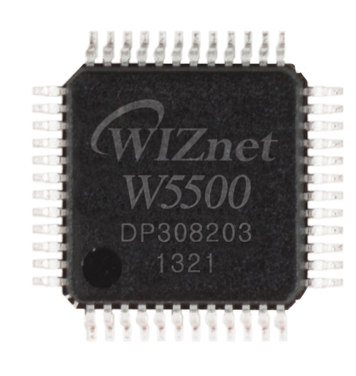
The heart of my questions revolves around the RJ45/Ethernet section. Employing the W5500 reference design, I grapple with conflicting information about the ideal distance between the W5500 IC and the magjack. Power plane separation, differential pair lengths, and magjack phase dot orientation pose specific challenges. Grounding strategies, especially under the magjack connector, demand careful consideration. The conundrum of chassis grounding and the use of non-conductive chassis mount RJ45 receptacles further adds to the complexity.
400kHz I2C Implementation:
Addressing the intricacies of the 400kHz I2C design, I explore the need for lowpass filters and slow-down resistors on SDA and SCL lines. The inclusion of MOSFET-based switching, controlled by the MCU, prompts questions about inrush spikes and the necessity of series resistors on gate connections.
SPI Connection and Capacitor Dilemmas:
I scrutinize the SPI connection, aiming for minimal length and considering the potential impact on electromagnetic interference. Additionally, I ponder the capacitor specifications, contemplating an upgrade to 2.2uF from 1uF for the AP7366 power regulator.
Conclusion:
Embarking on this certification journey, I find myself at the crossroads of meticulous design considerations and the quest for optimal EMI/EMC performance. Your insights and guidance are invaluable as I navigate the challenges posed by RJ45/Ethernet intricacies, I2C implementation nuances, and capacitor dilemmas. Thank you for joining me on this thrilling expedition!
The discussion revolves around the design and considerations for an Ethernet board, particularly involving the W5500 chip and its integration with other components. Here are some key points and recommendations from the conversation:
Metal Chassis Feedthrough RJ45 Connectors: The need for metal chassis feedthrough RJ45 connectors is highlighted, with a suggestion to consider their impact on return currents.
Traces Going to Layer 4: Attention is drawn to return currents for traces going to layer 4, especially those switching reference planes. The recommendation is to swap pours on layers 3 and 4, creating a solid ground plane on layer 3 and adding ground stitching vias next to signal vias.
Guard Ring Around PCB: The suggestion is to implement a ground guard ring around the edge of the PCB on all four layers, either stitching them with vias or making the board edge plated.
Filtering for Signals Going Off-Board: It's advised to implement filtering for signals that go off-board, particularly mentioning SCL and SDA, to reduce the potential for noise.
Configurable Slope Limiting for Atmega: The recommendation is to employ configurable slope limiting for Atmega pins to maintain signal integrity.
Concerns About the RJ45 Connector: The discussion touches on potential issues related to the RJ45 connector being connected to the outside of the chassis and the need for additional filter countermeasures.
Power Supply Filtering: The power supply is mentioned to have at least a common-mode choke and pi filter inside the power inlet, providing potential protection against conducted emissions.
Concerns About Stackup and Ground Plane: A concern is raised about the PCB stackup, suggesting potential issues with the overlap of the EM field for return currents and the power plane. Recommendations include considering alternative stackups and referencing a video by Rick Hartley on the importance of PCB stackup.
Routing and Length Matching for Differential Pairs: Attention is given to routing and length matching for differential pairs, with specific considerations for SPI and I2C traces. The importance of proper ground reference for differential pairs is emphasized.
Addressing EMI Issues: Various suggestions and discussions around EMI issues, including the placement of termination resistors, EMI resistors, and the potential impact of capacitors on TX lines.
Ethernet Speed and MCU Compatibility: Questions are raised about the compatibility of a 10MHz CPU with 100Mbit Ethernet, with explanations provided regarding the W5500 chip's functionality as an Ethernet-to-SPI/UART interface.
Design Changes and Updates: The engineer makes several design changes based on the feedback received, including swapping layers in the stackup, addressing concerns about the RJ45 connector, and optimizing the placement of components.
Measurement and Testing Equipment: The engineer mentions plans to invest in a spectrum analyzer and TEM cells for measuring EMI.
Feedback on PCB Layout: Feedback is provided on the PCB layout, including suggestions for optimizing the placement of components, addressing silk screen issues, and considering the use of through-hole capacitors.
Educational Resources: Recommendations are made for educational resources, including videos by Rick Hartley and discussions about PCB stackup considerations.
The ongoing dialogue reflects a collaborative effort to address potential issues in the PCB design and optimize the layout for better performance and compliance with standards. The engineer actively considers and implements suggestions from the community, demonstrating a commitment to thorough design review and improvement.


