
Building the ‘ESP32-Gateway’: Why the First Step in IoT is Professional Hardware
Bridging the Gap: My #30DaysOfEngineering Journey Begins
1) Introduction
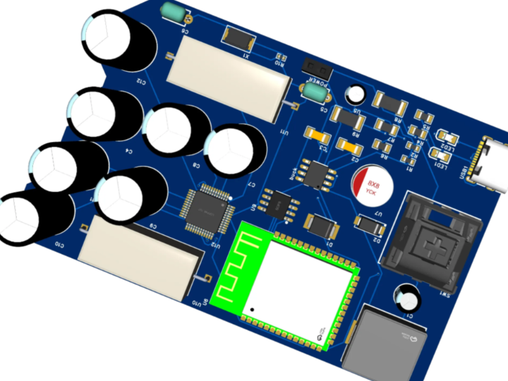
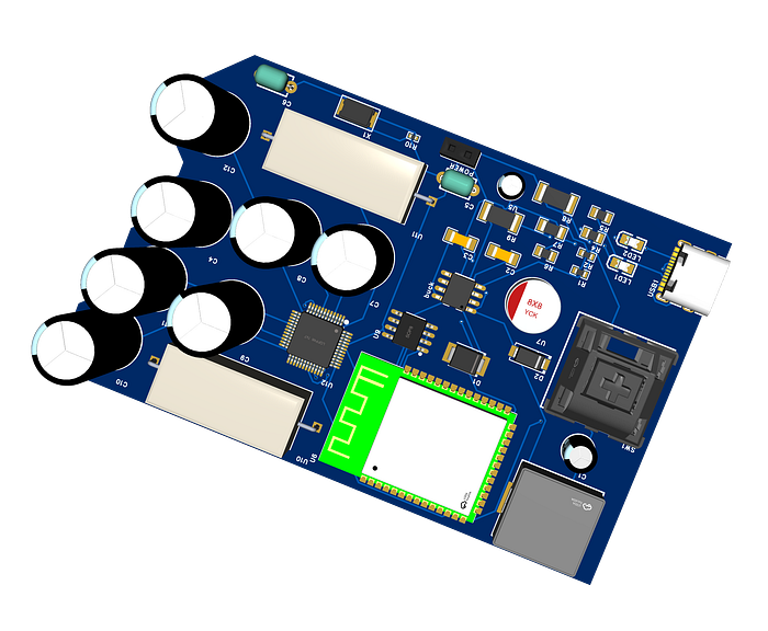
In many IoT prototypes, development starts with firmware or cloud dashboards. That approach works for demos, but it often breaks down in real deployments where power quality, cable length, electrical noise, and deterministic communication matter more than raw feature count. In the original project, Redwan Ahmmed positions the ESP32-Gateway v1.0 as a professional hardware foundation for industrial IoT, combining an ESP32-S3, a W5500 Ethernet controller, RS485/Modbus connectivity, and a 9V–24V wide-input power stage into a single gateway board. He also describes the firmware direction as a non-blocking FreeRTOS design so that network and field-bus communication can operate concurrently.
This is the correct starting point for industrial edge systems. Ethernet is preferred where low latency and predictable connectivity are required, RS485 remains one of the most common physical layers in industrial sensing and automation, and a wide-input supply is necessary when the board must survive real control-cabinet power rails instead of depending on USB alone. The project also highlights future upgrades such as isolation, backup power, and hardware security, which are exactly the design directions expected in production-grade gateways.
This article restructures that concept into a complete maker.wiznet.io tutorial. It explains not only what the gateway does, but also why each hardware block matters and how to implement a practical first version.
2) Required Components
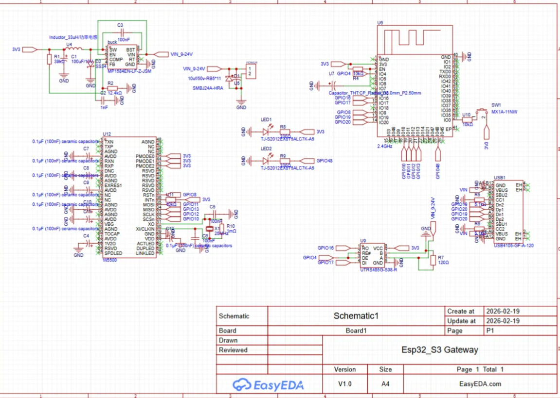
The original article explicitly identifies the key architectural blocks: ESP32-S3, W5500 Ethernet, RS485/Modbus, and a 9V–24V input buck converter. The list below expands those blocks into a practical buildable set.
Core Processing
- ESP32-S3 module or development board
- 3.3V regulator section if using a bare module
- USB-UART circuit for programming and debug
Networking
- WIZnet W5500 Ethernet controller
- RJ45 connector with integrated magnetics or separate magjack
- SPI routing between ESP32-S3 and W5500
- Interrupt and reset lines for reliable link management
Industrial Field Interface
- RS485 transceiver module or IC
- Terminal block connector for A/B/GND
- Direction control pin for half-duplex communication
- Optional TVS diode and termination resistor
Power
- 9V–24V input terminal
- Wide-input buck converter to 5V or 3.3V rail
- Reverse-polarity protection
- Bulk and decoupling capacitors
- Optional fuse or resettable polyfuse
Development Tools
- EasyEDA Pro for schematic and PCB layout
- ESP-IDF or Arduino IDE for firmware
- USB cable
- Ethernet cable and router/switch
- USB-to-RS485 adapter for field testing
Optional Enhancements for v2.0
- Opto-isolated RS485
- Li-ion UPS or supercapacitor-backed hold-up stage
- ATECC608A secure element
These future directions are mentioned directly in the source article as part of the roadmap.
3) Hardware Setup
The gateway can be understood as four major hardware domains:
A. ESP32-S3 Control Domain
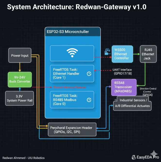
The ESP32-S3 is the main MCU. It runs the application logic, schedules tasks with FreeRTOS, handles sensor polling or protocol translation, and controls both the Ethernet and serial buses. Espressif documents the ESP32-S3 as a 2.4 GHz Wi-Fi + Bluetooth LE SoC in the ESP32 family, and the wider ESP-IDF framework provides the official development environment for this class of device.
B. Ethernet Domain with W5500
The W5500 is connected over SPI to provide stable wired networking. This choice is important: instead of relying only on Wi-Fi in electrically noisy or congested environments, the board gets a dedicated Ethernet controller with hardware TCP/IP support. WIZnet’s datasheet states that the W5500 uses SPI and supports high-speed network communication with integrated hardwired TCP/IP functionality.
C. RS485/Modbus Domain
The RS485 section connects the gateway to field devices such as industrial sensors, PLC-adjacent nodes, or distributed meters. The source article emphasizes long-distance operation and noisy environments as the reason for selecting RS485/Modbus. TI’s RS-485 design guide describes RS-485 as a balanced interface standard widely used in industrial applications.
D. Power Domain
The board accepts 9V–24V input and converts it down to logic rails. This is one of the strongest signs that the design is intended for real deployment rather than desk-only prototyping. Industrial control panels often expose higher and noisier DC rails than USB-powered maker boards. The original article explicitly frames this wide-input supply as necessary for real-world systems.
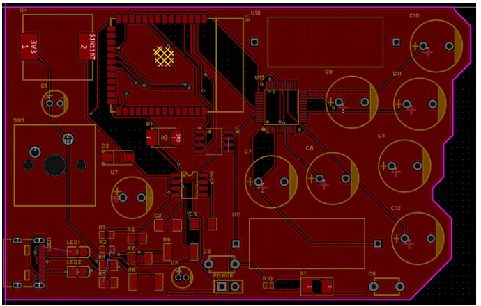
Recommended PCB Design Notes
The author credits EasyEDA Pro for helping move the design toward manufacturing-ready layout using DRC and advanced routing. EasyEDA Pro documentation confirms support for design rules and differential-pair workflows, both of which are useful when handling sensitive signal paths and cleaner routing discipline.
Practical layout advice:
- Keep the buck converter physically separated from sensitive SPI and UART traces.
- Use a solid ground plane.
- Place decoupling capacitors close to the ESP32-S3 and W5500 power pins.
- Keep the SPI traces short between ESP32-S3 and W5500.
- Put RS485 protection and terminal blocks near the board edge.
- Reserve footprints for termination, biasing, and optional isolation.
4) Interface Explanation
SPI: ESP32-S3 ↔ W5500
SPI is used because the W5500 is an SPI Ethernet controller. The ESP32-S3 acts as the SPI master, and the W5500 acts as the slave. Standard lines are:
- SCLK
- MOSI
- MISO
- CS
- INT
- RST
This connection allows the MCU to configure sockets, send/receive packets, and monitor link status. W5500’s hardwired TCP/IP offloads much of the Ethernet stack handling from the MCU, which is especially helpful in gateway applications that must also manage field-bus tasks.
UART: ESP32-S3 ↔ RS485 Transceiver
The RS485 transceiver is typically connected to one ESP32-S3 UART. UART TX/RX carry serial data, and a dedicated GPIO controls DE/RE for half-duplex direction switching. This is a common architecture for Modbus RTU gateways:
- UART TX → DI
- UART RX ← RO
- GPIO → DE/RE
- A/B lines → field bus
FreeRTOS Tasking Model
The source article specifically mentions a non-blocking FreeRTOS design where industrial bus communication and Ethernet run concurrently. ESP-IDF documentation confirms that Espressif provides FreeRTOS support, including SMP-capable implementations for dual-core devices such as ESP32-S3.
A practical task split is:
- Ethernet task: monitors link and serves TCP/UDP or HTTP
- RS485 poll task: queries field devices at fixed intervals
- Gateway logic task: translates Modbus data into network payloads
- Watchdog/health task: checks link, queue depth, and fault flags
RMII vs SPI
This project uses SPI Ethernet with W5500, not RMII Ethernet. RMII is usually used with PHY-based integrated MAC designs, while W5500 simplifies the hardware by encapsulating the Ethernet controller and TCP/IP stack in a single SPI device. For a compact custom board, SPI Ethernet often reduces complexity and speeds up bring-up.
5) Conclusion
This ESP32-Gateway project is more than just a single build—it marks the beginning of a structured approach toward industrial-grade IoT hardware design. By prioritizing stable power architecture, reliable Ethernet communication with W5500, and robust RS485 integration, this first iteration establishes a solid foundation for future expansion.
As the first article in this series, this project sets the direction for building practical, field-ready IoT systems rather than simple prototypes. Future iterations will refine hardware reliability, enhance security, and expand functionality.
This is only the starting point—and the expectation is that this series will continue to evolve into a complete, production-ready gateway platform.
Q1: Why is a dedicated hardware gateway preferred over standard Wi-Fi boards for Industrial IoT? A: Standard Wi-Fi-based boards are often prone to signal interference and latency issues in industrial environments. Professional hardware, like the ESP32-Gateway, prioritizes Deterministic Communication. By integrating the W5500 Ethernet controller, it ensures low-latency, hardwired reliability that Wi-Fi cannot guarantee, which is critical for real-time industrial automation and robotics.
Q2: How does the ESP32-Gateway handle long-range sensor communication in noisy environments? A: The gateway utilizes the RS485/Modbus protocol, the global standard for industrial bus communication. This allows for robust, two-way data exchange over distances of up to 1.2 kilometers. Unlike standard I2C or UART, RS485 is differential, making it highly resistant to electromagnetic noise found on factory floors or in large-scale infrastructure.
Q3: What makes the power management system of this gateway "Industrial Grade"? A: While hobbyist projects typically rely on 5V USB power, industrial systems operate on diverse and often "noisy" power rails. This gateway features an integrated 9V-24V Wide-Input Buck Converter. This hardware design ensures stable power delivery and compatibility with standard PLC (Programmable Logic Controller) power levels, protecting the internal circuitry from voltage fluctuations.
Q4: What is the significance of using FreeRTOS in the ESP32-S3 firmware design? A: Industrial reliability requires multitasking without bottlenecks. By leveraging a non-blocking FreeRTOS design, the ESP32-Gateway can handle high-priority RS485 bus communication and Ethernet network operations concurrently. This real-time operating system approach ensures that mission-critical sensor readings are never delayed by background network tasks, maintaining peak system efficiency.
Q5: How does the project address the "Hardware Root of Trust" for future IoT security? A: To bridge the gap between "Internet of Things" and "Internet of Threats," the roadmap for v2.0 includes the integration of the ATECC608A Hardware Security Module (HSM). This provides a physical Hardware Root of Trust, enabling encrypted cloud authentication and secure boot processes that are significantly more difficult to breach than software-only security layers.