
MODBUS TCP based I/O for 3D Printer automation
This project envisions a MODBUS TCP-based I/O controller tailored for 3D printers.
It would help to control various aspects of 3D printing.
WIZnet - W7500
x 1
Surf5 Board

seeed - Grove - 2-Channel SPDT Relay
x 1
Relays for Power and Light Control (Equivalent)

seeed - Grove - Universal 4 Pin Buckled 5cm Cable (5 PCs Pack)
x 1
Wires to 3D printer Main Board
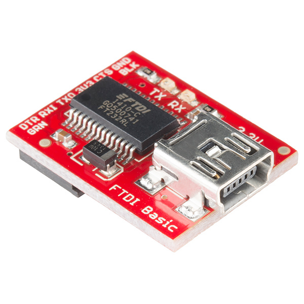
sparkfun - SparkFun FTDI Basic Breakout - 3.3V
x 1
Emulating 3D Printer Main Board
WIZnet - WIZnet io Library
x 1
Surf 5 Library for W7500
microsoft - VS Code
x 1
Development Evironment

ARM - KEIL5
x 1
GNU ARM GCC Tool Chain
Introduction
This project originates from the need to have external control on 3D printers apart from the Firmware / Execution already supported internally. One of the most common Industrial control protocols is MODBUS and its also supported over TCP. The same was chosen to implement the control of Relays. Additionally to send GCode commands to the 3D printer an Socket
based TCP/IP to UART server has been envisioned.
Assumptions
- Ethernet capability and DHCP Server is already present in the Network.
- Dual Relay board used is not actually connected to AC power of the 3D printer. However the same is assumed to be easily be achievable.
- FTDI USB-to-UART Board is used to emulate the communications with 3D printer. It is assumed that the same can be replaced with an actual connection with 3D printer main-board.
- Even though the WIZPoE-P1 board is attached the Surf 5 Board is powered using USB. It is assumed that the same can be easily changed to a PoE configuration when needed.
Hardware
The project consists of 3 main components:
- Surf 5 Board based on W7500 iMCU Microcontroller from WIZNet.
- Dual Relay Board with 5V Isolated control.
- FTDI USB-to-UART Board configured for
3.3V TTL level.
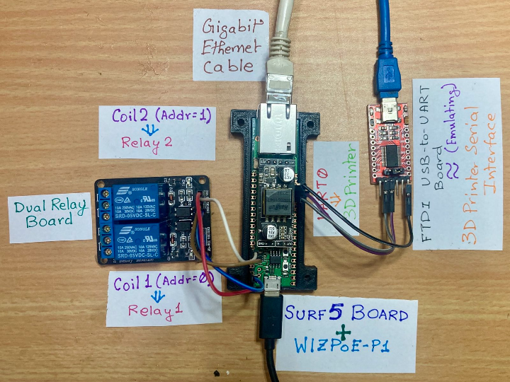
Here is a picture of how the actual assembly looks like:
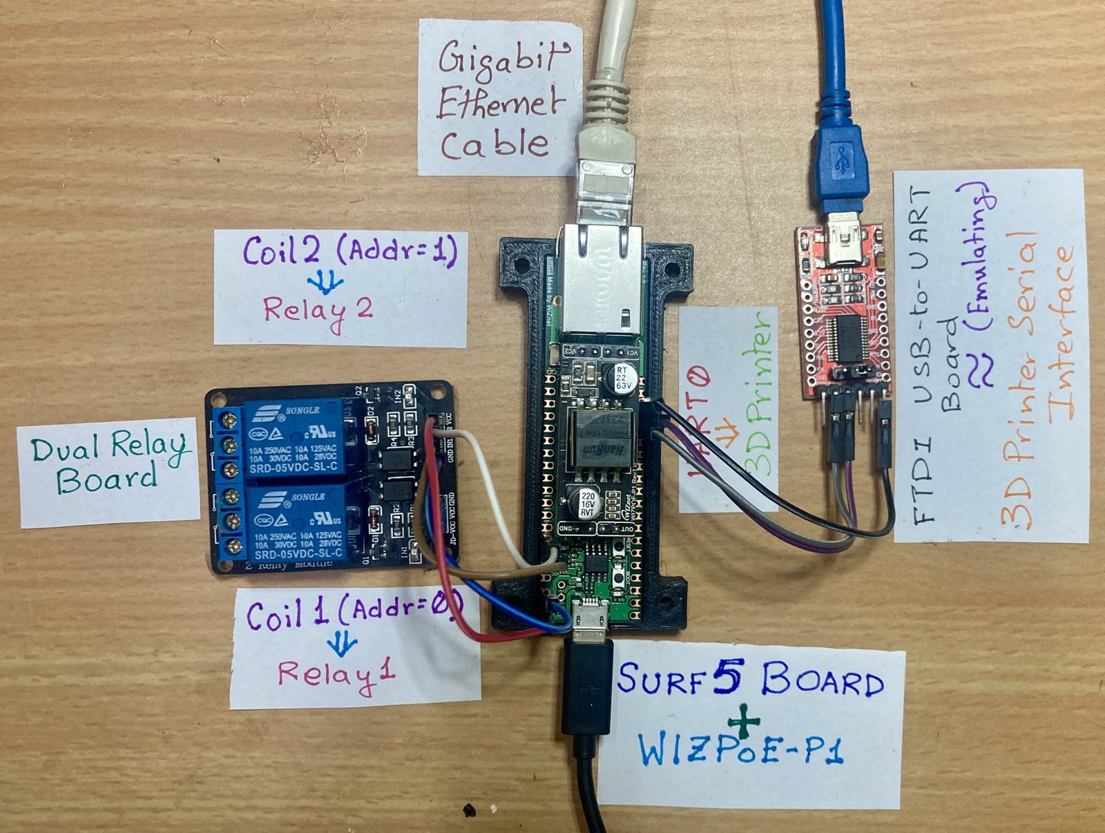
Hardware Setup
Here is the Figure showing the Hardware setup :
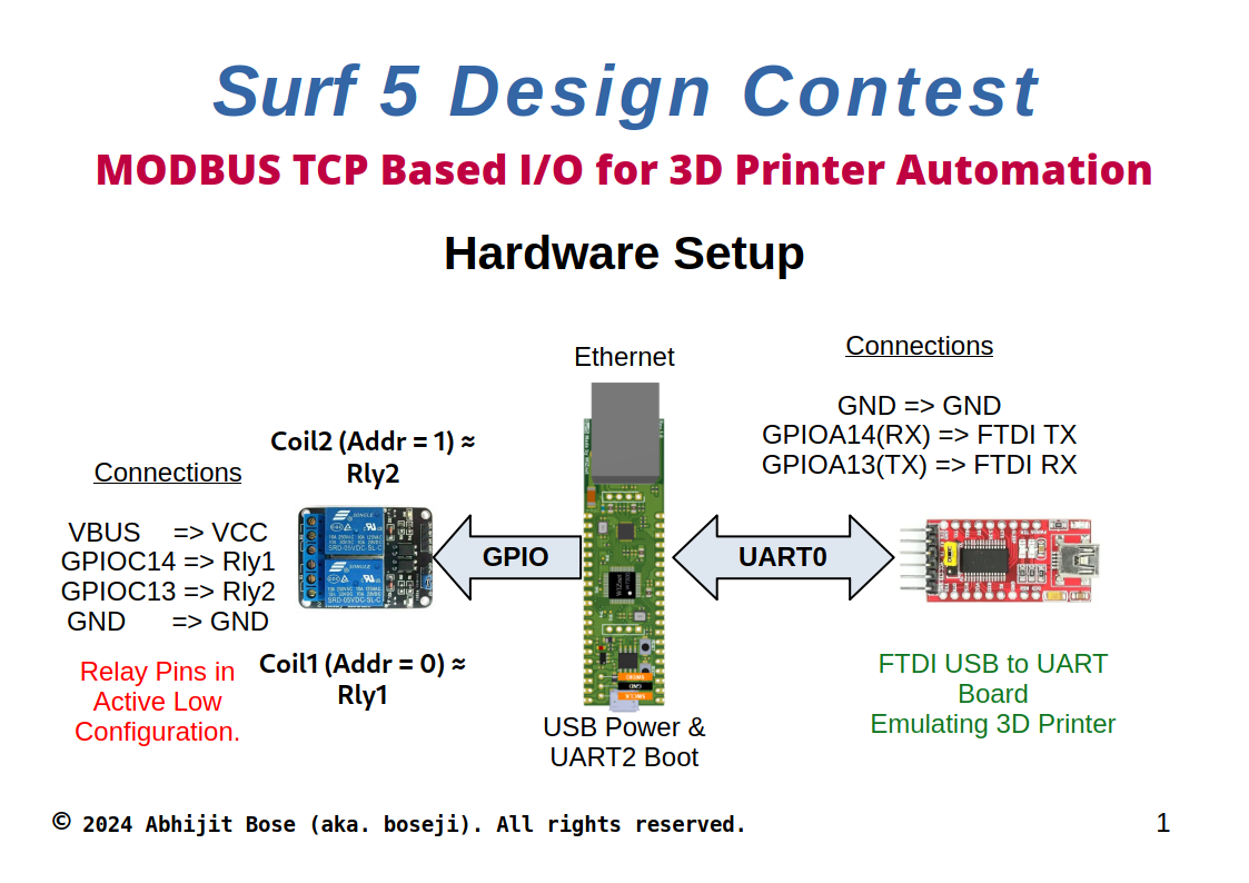
Hardware Connections
The Dual Relay Board is connected as follows:
| Surf 5 Board Pin | Dual Relay Board Pin |
| 38 - GND | 1 - GND |
| 35 - GPIOC14 | 2 - IN1 |
| 36 - GPIOC13 | 3 - IN2 |
| 40 - VBUS | 40 - VBUS |
The FTDI USB-to-UART Board is connected as follows:
| Surf 5 Board Pin | FTDI USB-to-UART Board Pin |
| 18 - GND | 1 - GND |
| 17 - GPIOA14 (UART0 RX) | 4 - TX |
| 16 - GPIOA13 (UART0 TX) | 5 - RX |
Due to unavailability of POE for the network the Surf 5 Board is powered up using USB cable.
Firmware
In order to easy firmware development on the Surf 5 Board the original Firmware has been modified to support Linux development setup.
Firmware Development Setup
The following tools were used in Firmware development:
- Visual Studio Code by Microsoft.
- CMAKE , GNU Make.
- GNU ARM Tools for compilation.
- Modified Firmware libraries (by boseji.) to support Linux based development.
Modified Firmware for Linux OS based Development
Here is the location of the Original Firmware supplied by WizNet :
https://github.com/Wiznet/W7500x-Surf5
Here is the location of the Modified Firmware (by boseji.) to support Linux Development:
https://github.com/boseji/W7500x-Surf5/tree/main
The Install process for dependencies is explained in the following document:
https://github.com/boseji/W7500x-Surf5/blob/main/getting_started-linux.md
Firmware Architecture
Here is a picture showing the Firmware Architecture of this project:
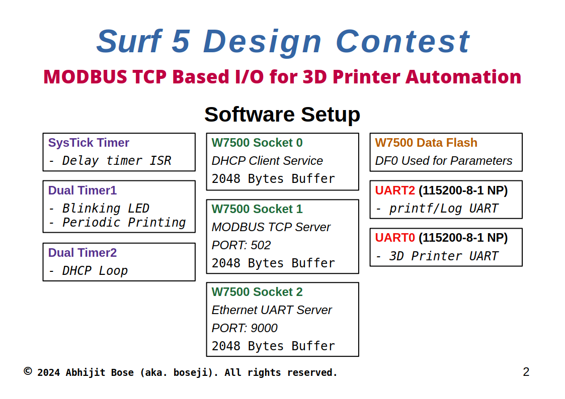
The TOE Peripheral of W7500 has been effectively used to serve a total of 3 Sockets. Additionally the internal Data flash is used to store the configurable parameters for MODBUS and UART connection.
The onboard LED on the Surf 5 board shows the status of the system.
When the connection is lost or a critical error happens in the firmware the LED blinks at a fast rate.
When the firmware is functioning properly the LED flashes at a slow rate of twice a second.
The DHCP Client is configured such that it automatically updates the IP Address of the system. Additionally, it is fault tolerant to help with accidental Ethernet cable disconnection or issues on the DHCP Server side.
MODBUS Server incorporates very few functions, specifically to control the Relays. The same can be extended as needed. In case any other functions are requested the same return a MODBUS standard bus exceptions. The MODBUS server is also responsible for decoding the MODBUS APDU and responding with errors in case parameters supplied in the functions are incorrect. This also fault tolerant and disconnects the Sockets when connection to network is lost.
Ethernet UART Server provides a way to stream commands back and forth between the client and the 3D Printer connected to UART0. The UART0 has an special Interrupt based receive buffer that gets automatically forwarded by the Ethernet UART Server to the client. The response time is optimized to roughly 100 milliseconds to help with the fast 3D Printer GCode transaction.
This is also fault tolerant to disconnections and securely terminates the transactions from the client removing 3D printer UART stall issues.
The UART2 is the boot program UART and is used as such for logging purposes.
The SysTick timer is used for generating Delay in order of milliseconds. It also helps with creating timestamps needed for the UART0 auto termination feature.
The Dual Timer 1 has 2 parts. The first part is used to blinking the onboard LED at a fixed rate. The second part is used for sending out the periodic log messages about the system status over UART2.
The Dual Timer 2 has only one half utilized to generate a 1 Second interrupt triggering the DHCP Client state machine.
MODBUS Firmware
Here is the configuration for the MODBUS Server in Firmware:
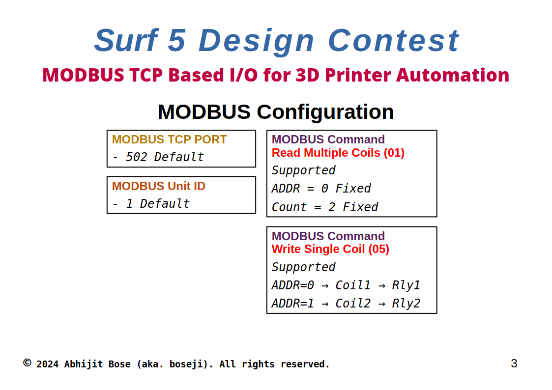
There only two function codes supported:
- Read Multiple Coils
- Write Single Coil
The options for the same are listed in the figure.
The Relay 1 is actually Coil 1 and is addressed by 0.
Similarly, Relay 2 is actually Coil 2 and is addressed by 1.
Any MODBUS Poll client can be used to read back the status of the Relays.
MODBUS Testing Script
In order to test out the MODBUS operation we are using Python library umodbus. Python scripts using the same is included in the supplied source code under the umodbus folder.
Just install the umodbus library by creating a virtual environment:
python3 -m venv venv
source ./venv/bin/activate

pip3 install umodbus
To test the operation edit the <ip-address> field in the read_coiils.py file.
message = tcp.read_coils(slave_id=1, starting_address=0, quantity=2)It would print the status of both relays.
As shown in the line the Unit ID is 1 and Starting address is 0 as determined in the MODBUS firmware.
Similarly to Turn ON and Off the Relays we need to edit and add the <ip-address> field in the write_coil.py file.
To Turn ON the Relay 1:
OnOff = 1
message = tcp.write_single_coil(slave_id=1, address=0, value=OnOff)
To Turn OFF the Relay 2:
OnOff = 0
message = tcp.write_single_coil(slave_id=1, address=1, value=OnOff)
ETHUART Server
This is the Ethernet TCP Socket Server that is connected to the 3D printer. It emulates a virtual UART connected directly to 3D Printer but over Ethernet. As indicated in the Firmware Architecture figure - This Server uses port 9000. This Port can be changed in the System Configuration stored in Data Flash 0. Connecting to this server is simple. Its a basic socket Server that can be connected as a ASCII Terminal. The BAUD rare on the Hardware UART is set at 115200 BAUD which is the common for most 3D printer along with 8-bit, No parity and 1 stop bit setting. This allows the hardware generic enough to work with any type of 3D printer.
However, since the output is a TTL 3.3V on the Surf 5 board one needs to hook this up directly to the Main-Board of the 3D Printer. In this case we are using a FTDI USB-to-UART Board to emulate such a Main-Board of 3D Printer. And a PC Serial terminal to actually respond to the commands sent.
ETHUART Testing Program
In order to test connection with the Ethernet UART server we are using the netcat command.
To install it use:
sudo apt install openbsd-netcatIn order to connect to the Server from the Client:
nc <ip-address> 9000Replace the <ip-address> with that of the Surf 5 Board. This would automatically connect and open a simple ASCII terminal to the Ethernet UART TCP Socket Server.
Firmware Location and Firmware Image for Programming
The firmware has been open sourced under the SPDX: GPL-3.0-or-later License.
It is available from the Repository link:
https://github.com/boseji/W7500x-Surf5/tree/project/src
The Binary Image src.bin that can be flashed using W7500isp program is available in the Binary folder under src directory.
Video Showing all the Different operations
-
Source Code

-
Picture and Connection setup

-
umodbus
Python Code for the MODBUS TCP communication