W5300 Network Performance Test
W5300 network performance test using W5300 TOE Shield.

This document guides code optimization and a series of processes for network performance test using the WIZnet's ethernet product with built-in W5300 - W5300 TOE Shield.
I will use W5300-TOE-C produced by WIZnet as an example of W5300 TOE Shield.
1. H/W Preparation
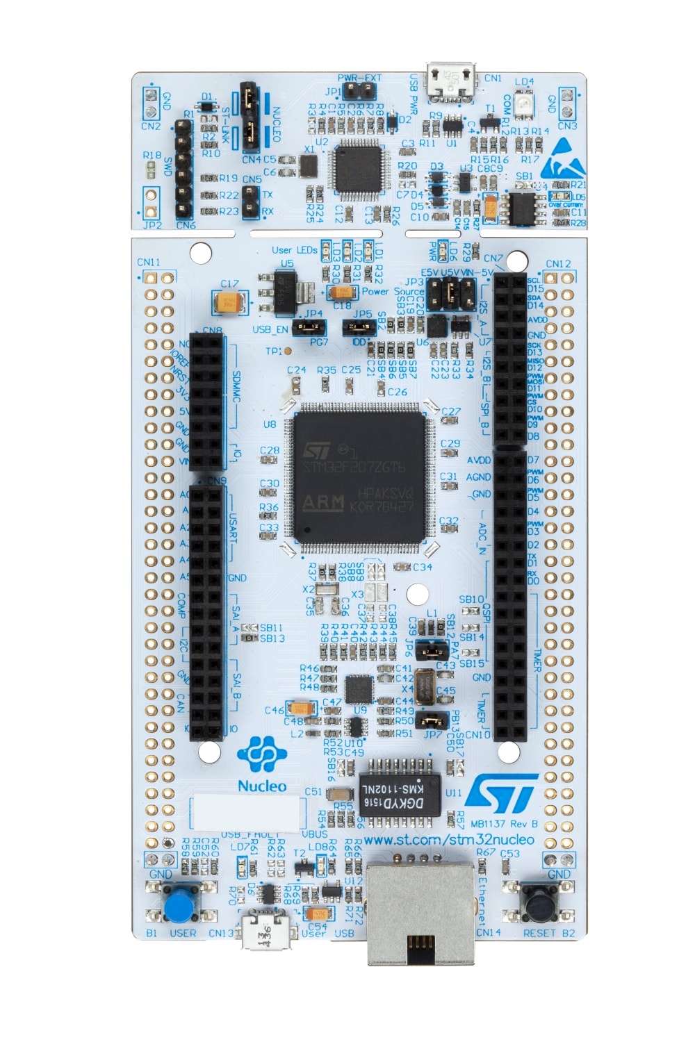
The W5300 TOE Shield is a board that enables high-speed bus communication with the W5300 and ST's Cortex MCU.
More details can be found at below link:
The W5300 TOE Shield is a board that can be mounted on STM32 Nucleo-144 boards.
Working can not be performed without the STM32 Nucleo-144 boards, and the NUCLEO-F207ZG, NUCLEO-F429ZI, NUCLEO-F439ZI, NUCLEO-F722ZE, NUCLEO-F756ZG and NUCLEO-F767ZI boards are currently supported.
And the ST-LINK pin was changed due to overlapping use of the FMC(Flexible Memory controller) data pin to control the W5300 built-in the W5300 TOE Shield and the ST-LINK pin of the STM32 Nucleo-144 board.
- STLK_RX[STM32F103CBT6_PA3] : PD8 → PC10
- STLK_TX[STM32F103CBT6_PA2] : PD9 → PC11
Therefore, in order to use the ST-LINK of the STM32 Nucleo-144 board, minor settings are required for the W5300 TOE Shield and STM32 Nucleo-144 board.
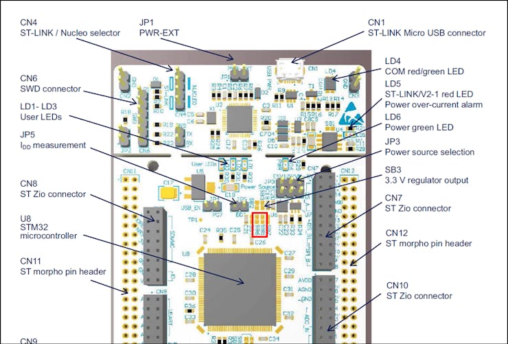
① Remove SB5 and SB6 from the top of the STM32 Nucleo-144 board.
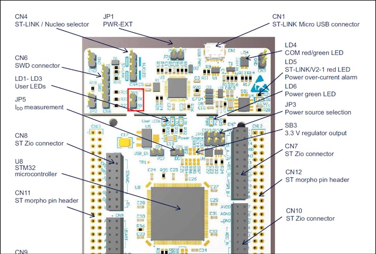
② With the W5300 TOE Shield and STM32 Nucleo-144 board combined, connect PC10, PC11 of the W5300 TOE Shield and CN5 TX, RX of the top of the STM32 Nucleo-144 board with jumper cables.
- W5300 TOE Shield : PC10 - STM32 Nucleo-144 board : RX
- W5300 TOE Shield : PC11 - STM32 Nucleo-144 board : TX
I used NUCLEO-F429ZI, so please refer to it,
follow the steps below to control the W5300 TOE Shield, firmware upload and run.
① Combine W5300 TOE Shield with STM32 Nucleo-144 board.
② Connect ethernet cable to W5300 TOE Shield ethernet port.
③ Connect STM32 Nucleo-144 board to desktop or laptop using 5 pin micro USB cable.
2. S/W Preparation
The following serial terminal program and network performance test tool are required for network performance test, download and install from below links.
I used AX2, so please refer to it.
- Tera Term
- AX1
- AX2
3. Clock Configuration
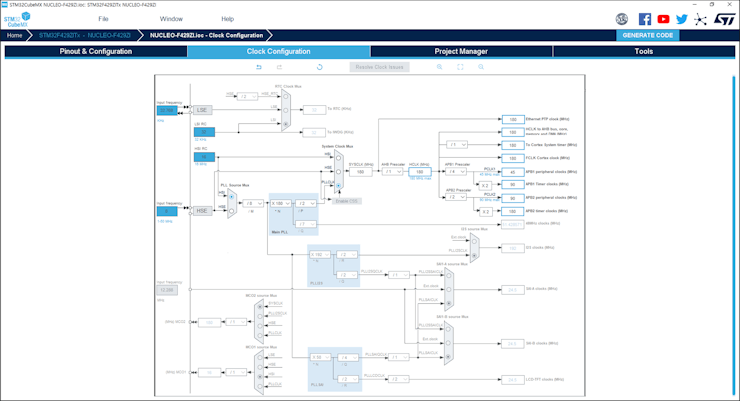
To use the maximum performance of NUCLEO-F429ZI, the clock of STM32F429ZI built-in NUCLEO-F429ZI is set to 180MHz, which is the maximum clock.
4. Source Code Optimization
In order to use maximum performance, it should be optimized not to go through unnecessary routines in the send/receive part.
#include <stdint.h>

#include "wizchip_conf.h"
#include "w5x00_bus.h"

(...)

void WIZCHIP_WRITE(uint32_t AddrSel, uint16_t wb)
{
#if 1
  _W5300_DATA(AddrSel) = wb;
#else
  WIZCHIP_CRITICAL_ENTER();
  WIZCHIP.CS._select();

#if ((_WIZCHIP_IO_MODE_ == _WIZCHIP_IO_MODE_BUS_DIR_))
#if (_WIZCHIP_IO_BUS_WIDTH_ == 8)
  WIZCHIP.IF.BUS._write_data(AddrSel, (uint8_t)(wb >> 8));
  WIZCHIP.IF.BUS._write_data(WIZCHIP_OFFSET_INC(AddrSel, 1), (uint8_t)wb);
#elif (_WIZCHIP_IO_BUS_WIDTH_ == 16)
  WIZCHIP.IF.BUS._write_data(AddrSel, wb);
#else
#error "Abnoraml _WIZCHIP_IO_BUS_WIDTH_. Should be 8 or 16"
#endif
#elif ((_WIZCHIP_IO_MODE_ == _WIZCHIP_IO_MODE_BUS_INDIR_))
#if (_WIZCHIP_IO_BUS_WIDTH_ == 8)
  WIZCHIP.IF.BUS._write_data(IDM_AR, (uint8_t)(AddrSel >> 8));
  WIZCHIP.IF.BUS._write_data(WIZCHIP_OFFSET_INC(IDM_AR, 1), (uint8_t)AddrSel);
  WIZCHIP.IF.BUS._write_data(IDM_DR, (uint8_t)(wb >> 8));
  WIZCHIP.IF.BUS._write_data(WIZCHIP_OFFSET_INC(IDM_DR, 1), (uint8_t)wb);
#elif (_WIZCHIP_IO_BUS_WIDTH_ == 16)
  WIZCHIP.IF.BUS._write_data(IDM_AR, (uint16_t)AddrSel);
  WIZCHIP.IF.BUS._write_data(IDM_DR, wb);
#else
#error "Abnoraml _WIZCHIP_IO_BUS_WIDTH_. Should be 8 or 16"
#endif
#else
#error "Unknown _WIZCHIP_IO_MODE_ in W5300. !!!"
#endif

  WIZCHIP.CS._deselect();
  WIZCHIP_CRITICAL_EXIT();
#endif
}

uint16_t WIZCHIP_READ(uint32_t AddrSel)
{
#if 1
  return _W5300_DATA(AddrSel);
#else
  uint16_t ret;

  WIZCHIP_CRITICAL_ENTER();
  WIZCHIP.CS._select();

#if ((_WIZCHIP_IO_MODE_ == _WIZCHIP_IO_MODE_BUS_DIR_))
#if (_WIZCHIP_IO_BUS_WIDTH_ == 8)
  ret = (((uint16_t)WIZCHIP.IF.BUS._read_data(AddrSel)) << 8) |
        (((uint16_t)WIZCHIP.IF.BUS._read_data(WIZCHIP_OFFSET_INC(AddrSel, 1))) & 0x00FF);
#elif (_WIZCHIP_IO_BUS_WIDTH_ == 16)
  ret = WIZCHIP.IF.BUS._read_data(AddrSel);
#else
#error "Abnoraml _WIZCHIP_IO_BUS_WIDTH_. Should be 8 or 16"
#endif
#elif ((_WIZCHIP_IO_MODE_ == _WIZCHIP_IO_MODE_BUS_INDIR_))
#if (_WIZCHIP_IO_BUS_WIDTH_ == 8)
  WIZCHIP.IF.BUS._write_data(IDM_AR, (uint8_t)(AddrSel >> 8));
  WIZCHIP.IF.BUS._write_data(WIZCHIP_OFFSET_INC(IDM_AR, 1), (uint8_t)AddrSel);
  ret = (((uint16_t)WIZCHIP.IF.BUS._read_data(IDM_DR)) << 8) |
        (((uint16_t)WIZCHIP.IF.BUS._read_data(WIZCHIP_OFFSET_INC(IDM_DR, 1))) & 0x00FF);
#elif (_WIZCHIP_IO_BUS_WIDTH_ == 16)
  WIZCHIP.IF.BUS._write_data(IDM_AR, (uint16_t)AddrSel);
  ret = WIZCHIP.IF.BUS._read_data(IDM_DR);
#else
#error "Abnoraml _WIZCHIP_IO_BUS_WIDTH_. Should be 8 or 16"
#endif
#else
#error "Unknown _WIZCHIP_IO_MODE_ in W5300. !!!"
#endif

  WIZCHIP.CS._deselect();
  WIZCHIP_CRITICAL_EXIT();
  return ret;
#endif
}
5. Example Settings
I used the Loopback example to test the network performance.
To test the network performance, minor settings shall be done in code.
① Setup FMC timing configuration.
Setup FMC timing configuration to use the maximum speed of FMC 'main.c' in 'W5300-TOE-C/Projects/NUCLEO-F429ZI/Core/Src/' directory.
Timing.AddressSetupTime = 1;
Timing.AddressHoldTime = 1;
Timing.DataSetupTime = 6;
Timing.BusTurnAroundDuration = 0;
Timing.CLKDivision = 2;
Timing.DataLatency = 2;
Timing.AccessMode = FMC_ACCESS_MODE_A;
② Select demo application.
To run the Loopback example, you must select the demo application in 'w5x00_demo.h' in 'W5300-TOE-C/Examples/' directory.
uncomment APP_LOOPBACK and comment the rest of the defined demo application macros.
// ----------------------------------------------------------------------------------------------------
// The application you wish to use should be uncommented
// ----------------------------------------------------------------------------------------------------
//#define APP_DHCP
//#define APP_DNS
//#define APP_HTTP_SERVER
//#define APP_MQTT_PUBLISH
//#define APP_MQTT_SUBSCRIBE
//#define APP_MQTT_PUBLISH_SUBSCRIBE
//#define APP_SNTP
//#define APP_TCP_CLIENT_OVER_SSL
#define APP_LOOPBACK
// ----------------------------------------------------------------------------------------------------
③ Setup network configuration.
Setup network configuration such as IP in 'main.c' in 'W5300-TOE-C/Projects/NUCLEO-F429ZI/Core/Src/' directory.
wiz_NetInfo net_info =
      {
          .mac = {0x00, 0x08, 0xDC, 0x12, 0x34, 0x56}, // MAC address
          .ip = {192, 168, 11, 2},                     // IP address
          .sn = {255, 255, 255, 0},                    // Subnet Mask
          .gw = {192, 168, 11, 1},                     // Gateway
          .dns = {8, 8, 8, 8},                         // DNS server
#ifdef APP_DHCP
          .dhcp = NETINFO_DHCP                         // Dynamic IP
#else
          .dhcp = NETINFO_STATIC                       // Static IP
#endif
      };
④ Setup Loopback configuration.
Setup loopback server port number in 'w5x00_loopback.c' in 'W5300-TOE-C/Examples/loopback/' directory.
#define PORT_LOOPBACK 5000
6. Build and Download
① After completing the Loopback example configuration, build in the IDE you are using.
② When the build is completed, download the firmware to the STM32 Nucleo-144 board.
7. Network Performance Test
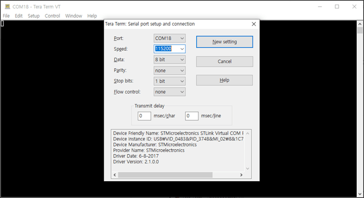
① Connect to the serial COM port of STM32 Nucleo-144 board with Tera Term.
② Reset your board.
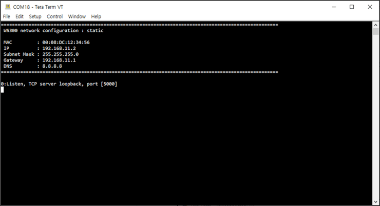
③ If the Loopback example works normally on STM32 Nucleo-144 board, you can see the network information of STM32 Nucleo-144 board and the loopback server is open.
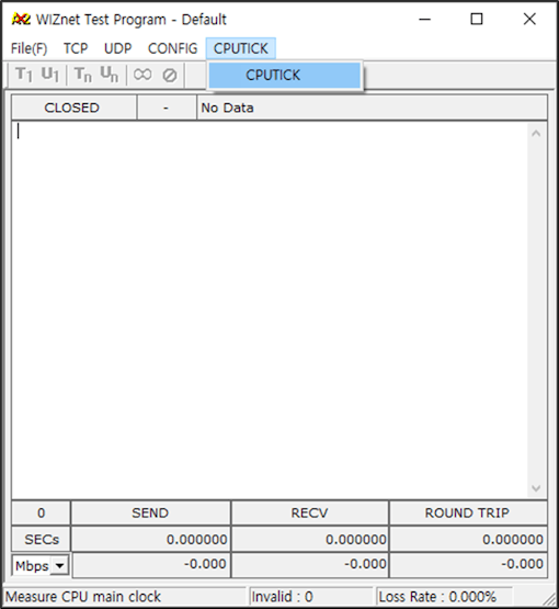
④ Run AX2, and initialize tick.
⑤ Connect to the open loopback server using AX2 TCP client. When connecting to the loopback server, you need to enter is the IP that was configured in Step 5, the port is 5000 by default.
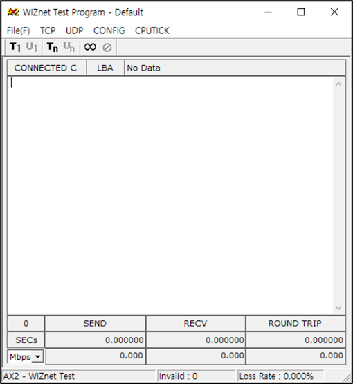
⑥ Once connected if you send data to the loopback server, you can see the network performance being measured.
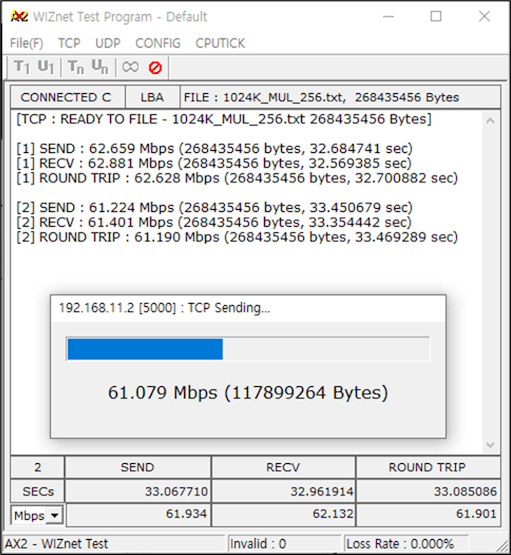
I've been able to see throughputs around 60 ~ 62Mbps.
