3D Magnetic S2E Robot Arm Remote
3D Magnetic S2E Robot Arm Remote
0
Components
Hardware componentsWIZnet WIZ750SR-TTL-EVB Kit
x 1
WIZnet WIZ750SR
x 1
nfineon 3D Magnetic Sensor 2Go
x 1
Dobot Magician
x 1
Arduino - Arduino IDE
x 1

Microsoft Windows 10
x 1
Project description
Story
Introduction
Robots have been taking a leap forward for the past couple of years, doing tasks ranging from industrial manufacturing to home cleaning. As the robotic advances, we will be focusing on remote controlling for matter of both safety and convinence. In this article, I will share a project that uses Infineon's 3D 2GO Magnetic Sensor and WIZnet S2E remote controller.
It's quiet easy to do a trigger for robotic arm to do one single function for demo purposes, but what we are trying to achieve is allowing users to fully control the robot arm over Serial to Ethernet and make any modifications they want.
Step 1: Gather Components
- Infineon 3D 2GO Sensor
- WIZnet WIZ750SR S2E
- Dobot Magician Arm
- Windows PC

Step 2: Connect the WIZ750SR
With developer edition, we first can power up the WIZ750SR through microUSB port. When everything is connected, we should see a green LED on for connected to the Ethernet, blue LED on for Ethernet add-on working, and red LED on for device being powered on as in the figure below.

After powering on, we can download the configuration tool from?https://github.com/Wiznet/WIZnet-S2E-Tool-GUI?to check whether the device is working. Easiest way here is to go through IP allocation via DHCP, then go back to static to auto fill out the network configuration.

The USB to UART driver can be downloaded if you are using the usb port. The Micro usb port that powers up the board will be the CP210x USB to UART Bridge used for debugging.
https://www.silabs.com/products/development-tools/software/usb-to-uart-bridge-vcp-drivers

We can use debug port to test out termite to test out the serial port, which can be downloaded from?https://www.compuphase.com/software_termite.htm?we should receive all the messages sending to COM port via debug USB.

As for the ethernet side we used ioninja's tcp server listening?http://ioninja.com/plugins/tcp-listener.html?Once that's successful we can test out whether these are in Sync, this allows to communicate from Serial to Ethernet.

Step 3: Install the IDEs
We first need to install all the drivers for WIZ750SR, in this case we only have Windows IDE available and they are being instructed through?https://github.com/Ricky-Kwon/WIZ750SR_Boot/wiki/Develop-environment-for-windows
For the most part, we need the following in our IDE, and this guide specifically used 64-bit windows.
From Ricky-Kwon's installation guide it seems that GNU Arm Eclipse Plugin web might not work, you can easily download, unzip and set that up to install as Eclipse's plugin as image below. Successful install would ask you to restart Eclipse.

After wards, we can copy the project and change accordingly:
git clone https://github.com/Ricky-Kwon/WIZ750SR_App.git

New firmware update can be seen from?https://wizwiki.net/wiki/doku.php?id=products:wiz750sr:developers:start#building_a_wiz750sr_development_environment
Step 4: Set Up the Infineon 3D Magnetic Sensor's Software
This part is a little tricky, if you've installed Evalkit for 3D Sensors you are likely to get stuck in an infinite loop.

So under this guide we have to install it via Arduino from Infineon's github pagehttps://github.com/Infineon/TLE493D-W2B6-3DMagnetic-SensorSo?we can add the TLE493D Library to Arduino.
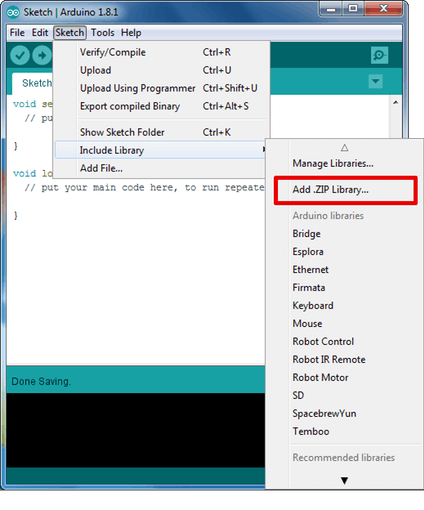
And once Arduino IDE is installed, we also have to add XMC as aprt of the device per Infineon's GitHub page:?https://github.com/Infineon/XMC-for-Arduino.


In short, we just need to add following to the preference so that XMC microcontroller shows up. And add XMC microcontroller as the board.
https://github.com/Infineon/Assets/releases/download/current/package_infineon_index.json
After that, we can start testing the magnet sensors from following code. Somehow there is a bug so you will need to do Tle493dMagnetic3DSensor.begin(); twice in order to get it running. Below is the Arduino code for the entire program:
#include <Tle493d_w2b6.h>
Tle493d_w2b6 Tle493dMagnetic3DSensor = Tle493d_w2b6();

float norm = 0;
bool start = false;
int frame = 0;
void setup() {
Serial.begin(9600);
while (!Serial);
pinMode(14, OUTPUT);
Tle493dMagnetic3DSensor.begin();
Tle493dMagnetic3DSensor.begin();
Tle493dMagnetic3DSensor.setWakeUpThreshold(1,-1,1,-1,1,-1);
Tle493dMagnetic3DSensor.disableTemp();
norm = Tle493dMagnetic3DSensor.getNorm();
}
void loop() {
Tle493dMagnetic3DSensor.updateData();
Serial.print(Tle493dMagnetic3DSensor.getNorm());
Serial.print(" ; ");
Serial.println(Tle493dMagnetic3DSensor.getAzimuth());
//It doubles when press down, and halves when releases
if((abs(Tle493dMagnetic3DSensor.getNorm()) > abs(norm*1.5))){
  start = true;
}
else if
((abs(Tle493dMagnetic3DSensor.getNorm()) < abs(norm/1.5)))
{
  start = false;
}
norm = Tle493dMagnetic3DSensor.getNorm();
if(start)
{
  digitalWrite(14, HIGH);
}
else
{
  digitalWrite(14, LOW);
}
delay(10);
}

The default JLink uses v6.00e from the installer, if you get the following error:
[Error] Infineon.DebuggerExceptions: It seems that JLink software is not installed please download from www.segger.com and install it. You can specify it by setting java property xmcFlasher.JLink.dllPath
Make sure you go to www.segger.com and install the latest JLink. the version v6.32d and Arduino 1.8.5 would compile and upload Arduino code quiet successfully.
Step 5: Screw the Knob and Test the Rotation
This step is fairly straightforward, making sure the chips are facing up.

After the knob is installed, we can test out on the same Arduino output to see both rotation as well as click. Specific field we care about here is norm for click and Azimuth for rotation.
Step 6: Setting Up Left-Right Rotation, Push Down and Pull Up
Now we can determine whether we are rotating left or right, as well as pulling up and pressing down. Left and Right can be seen through rotation, and pulling up and down is always double of what current value is fro the Knob. We can leverage LED on both front and back, so this way we know when it's rotating and when it goes front and back. We will be outputting the commands via serial.
Code below will output front, back, left, right and stop into S2E that's used to control the bot.
#include <Tle493d_w2b6.h>
Tle493d_w2b6 Tle493dMagnetic3DSensor = Tle493d_w2b6();
//for firing
float norm = 0;
float azimuth = 0;
bool x = false;
int frame = 0;
void setup() {
Serial.begin(115200);
while (!Serial);
pinMode(14, OUTPUT);
Tle493dMagnetic3DSensor.begin();
Tle493dMagnetic3DSensor.begin();
Tle493dMagnetic3DSensor.setWakeUpThreshold(1,-1,1,-1,1,-1);
Tle493dMagnetic3DSensor.disableTemp();
norm = Tle493dMagnetic3DSensor.getNorm();
}
void loop() {
  Tle493dMagnetic3DSensor.updateData();
  //Serial.print(Tle493dMagnetic3DSensor.getNorm());
  //Serial.print(" ; ");
  //Serial.println(Tle493dMagnetic3DSensor.getAzimuth());
  //It doubles when press down, and halves when releases
  if(Tle493dMagnetic3DSensor.getNorm() > 100)
  {
     Serial.println("front");
     digitalWrite(14, HIGH);
  }
  else if(Tle493dMagnetic3DSensor.getNorm() < 39)
  {
     Serial.println("back");
     digitalWrite(14, HIGH);
  }
  else if((int)(Tle493dMagnetic3DSensor.getAzimuth()*10) > (int)(azimuth * 10))
  {
     Serial.println("left");
  }
  else if((int)(Tle493dMagnetic3DSensor.getAzimuth()*10) < (int)(azimuth * 10))
  {
     Serial.println("right");
  }
  else
  {
     Serial.println("stop");
     digitalWrite(14, LOW);
  }
  azimuth = Tle493dMagnetic3DSensor.getAzimuth();
  norm = Tle493dMagnetic3DSensor.getNorm();
  delay(100);
}
When succeeded, it will come up with something like this:
The controls should output the command as following so that we can utilize the fully control of the robotic arm.
Step 7: Write TCPClient Code and Robot Control
To control the robot arm we can write the program in C#, in this article we will just go rotate left, right and extending arm. But first we need to connect to the sockets so that we can get the signal from WIZnet S2E. Full code can be seen and downloaded from the repo.
       public TcpClient tcpClient;
       private Thread receiveThread;
       private string left;
       private string right;
       private string front;
       private string back;
       private string stop;

       private void StartClient()
       {
           IPAddress ipAddress = IPAddress.Parse("192.168.1.200");
           tcpClient = new TcpClient();
           tcpClient.Connect(ipAddress, 5000);
           receiveThread = new Thread(receiverMessages);
           receiveThread.Start();
       }
       private void receiverMessages()
       {
           while (true)
           {
               NetworkStream ns = null;
               try
               {
                   ns = this.tcpClient.GetStream();
               }
               catch (InvalidOperationException ex)
               {
                   MessageBox.Show(ex.Message);
               }
               if (ns != null)
               {
                   StreamReader sr = new StreamReader(ns);
                   if (sr != null)
                   {
                       try
                       {
                           string message = sr.ReadLine();
                           receiveEvent(message);
                       }
                       catch (IOException e)
                       {
                           MessageBox.Show(e.ToString());
                       }
                   }
               }
           }
       }
       private void receiveEvent(string message)
       {
           Console.WriteLine(message);
           if (!isConnectted)
               return;
           if
           {
               active = true;
               currentCmd.isJoint = isJoint;
               currentCmd.cmd = (byte)JogCmdType.JogBNPressed;
               DobotDll.SetJOGCmd(ref currentCmd, false, ref cmdIndex);
           }
           else if (message.Contains(
           {
               active = true;
               currentCmd.isJoint = isJoint;
               currentCmd.cmd = (byte)JogCmdType.JogBNPressed;
               DobotDll.SetJOGCmd(ref currentCmd, false, ref cmdIndex);
           }
           else if (message.Contains(
           {
               active = true;
               currentCmd.isJoint = isJoint;
               currentCmd.cmd = (byte)JogCmdType.JogANPressed;
               DobotDll.SetJOGCmd(ref currentCmd, false, ref cmdIndex);
           }
           else if (message.Contains(
           {
               active = true;
               currentCmd.isJoint = isJoint;
               currentCmd.cmd = (byte)JogCmdType.JogAPPressed;
               DobotDll.SetJOGCmd(ref currentCmd, false, ref cmdIndex);
           }
           else if (message.Contains(
           {
               currentCmd.cmd = (byte)JogCmdType.JogIdle;
               DobotDll.SetJOGCmd(ref currentCmd, false, ref cmdIndex);
           }
           bool active = false;
           UInt64 cmdIndex = 0;
       }
At this point you should be able to control the robot arm via WIZ750SR S2E, as we are getting all the commands via Ethernet.
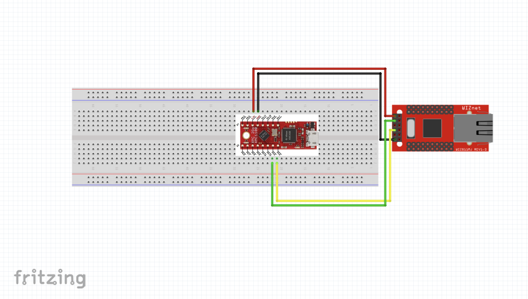
We can now finally hook up the 3D 2GO magnetic sensor to the WIZ750SR and control the robotic arm via S2E like the following. We are utilizing Infineon 3D 2GO to power up the WIZ750SR, and use TX/RX for the data transferring. On Arduino, make sure it is on serial onboard rather than to PC.

And wiring frame:
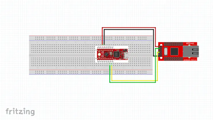
Below is when it's fully connected:

Once WIZ750SR and Infineon magnetic sensore are connected, run the app and you can then fully control the robotic arm through 3D 2GO via S2E. Feel free to make any comments or suggestions on this project!
When it's all done, you can use the current robotic arm to do some more complex tasks like below such as writing and drawing or picking up things.Some of the sample that's written by robot arm! :-)

Documents
-
3DGo Arduino S2E code.Arduino
Code used on Infineon 3DGo to be send into WIZNet S2E
-
Robotic Arm Receiver code
C# Code for Robotic Arm Receiver
-
Infineon 3DGo and WIZ750SR Wiring
The wiring diagram for Infineon 3DGo and WIZ750SR, which runs through RX TX serial port. connected directly to S2E