
WizFiBuddy - WizFi360 Based Work Assistance
WizFiBuddy is a tiny office assistance hardware which utilizes WizFi360.
WIZnet - WizFi360
x 1

Arduino - Arduino Mega 2560
x 1

dfrobot - Gravity I2C OLED-2864 Display
x 1

Arduino - Arduino IDE
x 1
Story
Introducing WizFiBuddy
WizFiBuddy is a tiny office assistance hardware which utilizes WizFi360.This utilizes WizFi360 Wi-Fi module from Wiznet .The WizFi360 wi-fi module is a cost-effective WiFi module that supports both TCP/IP and microcontrollers.
Yes , you have a Wi-Fi module and possibilities are endless.
Currently it has following features
- A Real time clock display with Wiznet's WizFi360 using SNTP(Simple Network Time Protocol) Server
- Semaphore Device - Lets add a small semaphore on your work desk. You can use it to tell whatever you want to people around it. For Example , because you need some concentration and you'd like your colleagues not to disturb you or to tell the status of the work you are managing , or say which mood are you today. The possibilities are endless.
Gather the Parts:
- Arduino Mega
- Grove_WizFi360 (I have designed a custom PCB which is compatible with Grove System ) - It's an Arduino compatible board. It has a white Grove connector, and make it convenient for using Grove products with the board.
- (0.96 Inch) I2C/IIC 128x64 OLED Display Module
- Grove - 4 pin Male Jumper to Grove 4 pin Conversion Cable
- Male to Female Jumper Cable
We will be using Arduino Mega for this project

Why not Arduino Uno ?
The Arduino Uno has only one hardware UART .You would have to go to a Mega to get more hardware serial pins. Also SoftwareSerial Library isn't capable of 115200 baud rate(despite "allowing this as settings).Some forums suggest as high as 57600 is workable.Wizfi360's default baud rate is 115200 and with SoftwareSerial Library, this is unreliable especially at higher baud rates.
You may check out my previous tutorial on hackster.io .I have explained few examples that how Wizfi360 can be controlled through AT Commands.
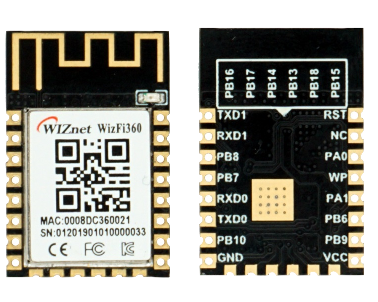
Grove_WizFi360 - Parts Overview:
About WizFi360

The WizFi360 wi-fi module is a cost-effective WiFi module that supports both TCP/IP and microcontrollers.
Connectivity is provided via 2.4Ghz wireless connection, WizFi360 is compatible with IEEE802.11 b/g/n standards and supports SoftAP, Station and SoftAP+Station modes.
WizFi360 provides time-to-market savings as a self-contained internet-enabling solution.
Features :
WizFi360 is perfect for mobiles wireless applications such as remote monitoring and sensor applications. Ease of integration and programming can vastly reduce development time and minimize system cost. The module has been designed to provide designers with a simple Wi-Fi solution that has following key features:
- WiFi 2.4G, 802.11 b/g/n
- Support Station / SoftAP / SoftAP+Station operation modes
- Support “Data pass-through” and “AT command data transfer” mode
- Support serial AT command configuration
- Support TCP Server / TCP Client / UDP operating mode
- Support configuration of operating channel 0 ~ 13
- Support auto 20MHz / 40MHz bandwidth
- Support WPA_PSK / WPA2_PSK encryption
- Serial port baud rate up from 600bps to 2Mbps with 16 common values
- Support up to 5 TCP / UDP links
- Obtaining IP address automatically from the DHCP server (Station mode)
- DHCP service for Wireless LAN clients (AP mode)
- Support DNS for communication with servers by domain name
- Support “Keep-Alive” to monitor TCP connection
- Support “Ping” for monitoring network status
- Built-in SNTP client for receiving the network time
- Support built-in unique MAC address and user configurable
- Support firmware upgrade by UART Download / OTA (via WLAN)
- Industrial grade (operating temperature range: -40 ° C ~ 85 ° C)
- KC, CE, FCC certification
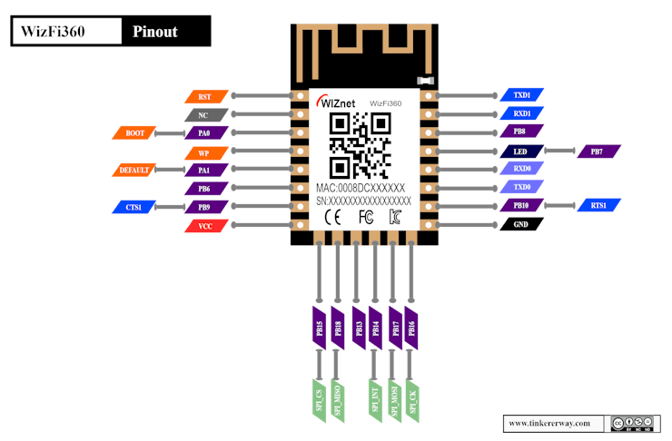
Pinouts and vector images can be downloaded from my GitHub repo :https://github.com/tinkererway/pinouts_tw/tree/main/WizNet/WizFi360
Grove_WizFi360 (I have designed a custom PCB which is compatible with Grove System ) - It's an Arduino compatible board. It has a white Grove connector, and make it convenient for using Grove products with the board.
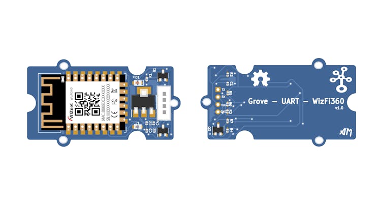
This version of Grove_WizFi360 is not compatible with 3.3 v microcontrollers, because no connectors are provided for it.
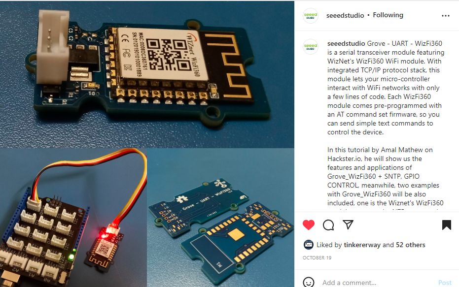
The Grove_WizFi360 was featured on seeedstudio social media platforms
(0.96 Inch) I2C/IIC 128x64 OLED Display Module(based on SSD1306):
Library Dependencies:
- Adafruit SSD1306 by Adafruit

How to install WizFi360 Arduino Library : https://github.com/amalmathewtech/Grove_WizFi360/tree/main/WizFi360_%20_Arduino%20_Library#readme
- Connect Arduino Mega to your PC with USB Cable
- Select Mega Board and Port accordingly
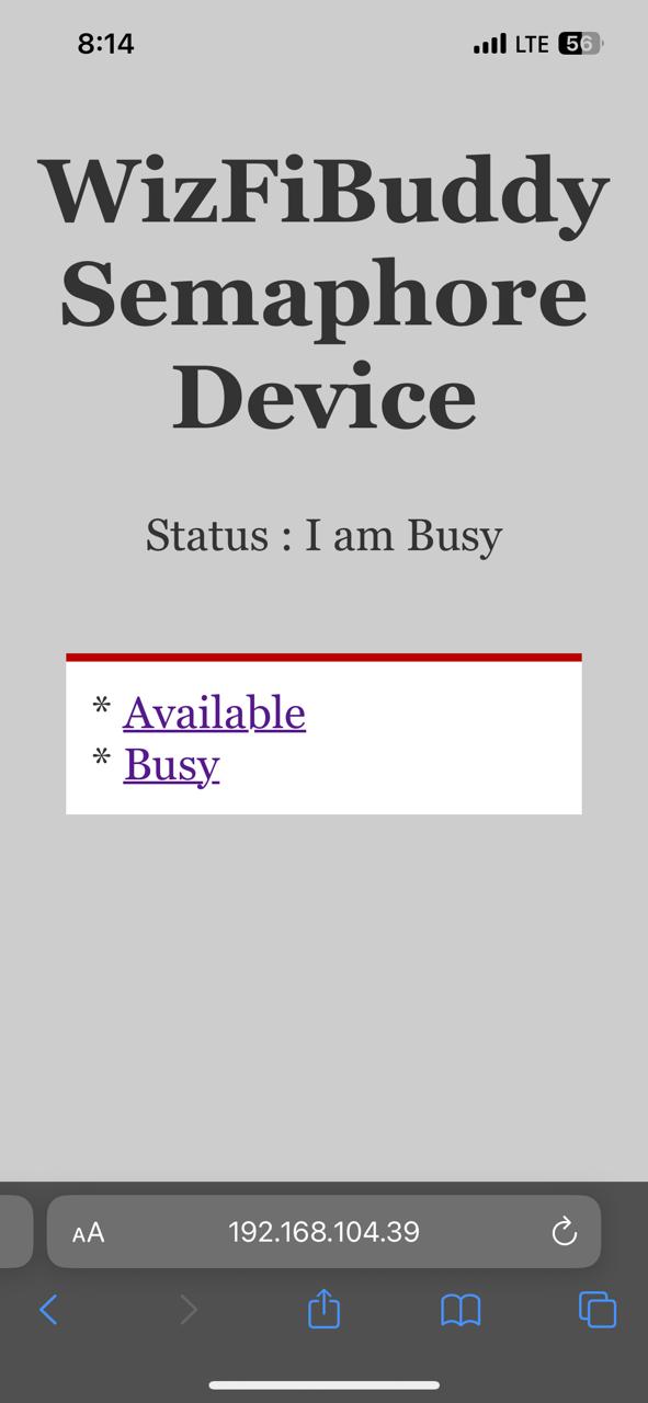
Web Server Controlled Semaphore Device
A semaphore at your office Desk !
Free to talk, "bit stressed", working on something important? Tell your Colleagues with the web server controlled semaphore. It's very simple to use. Open a browser and type the wizfi360's IP address. Your webserver will have option to inform "you are busy " or "you are available"
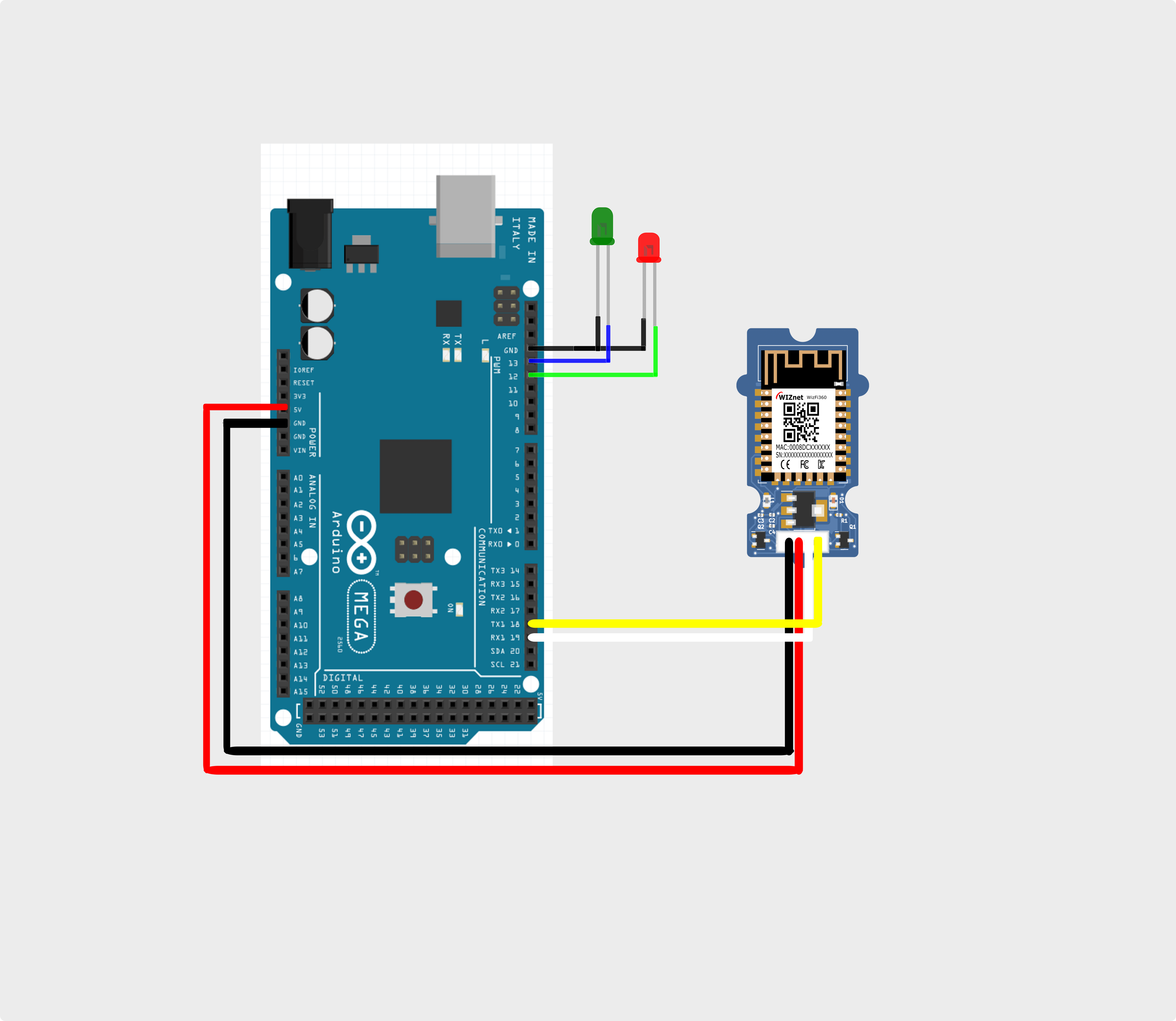
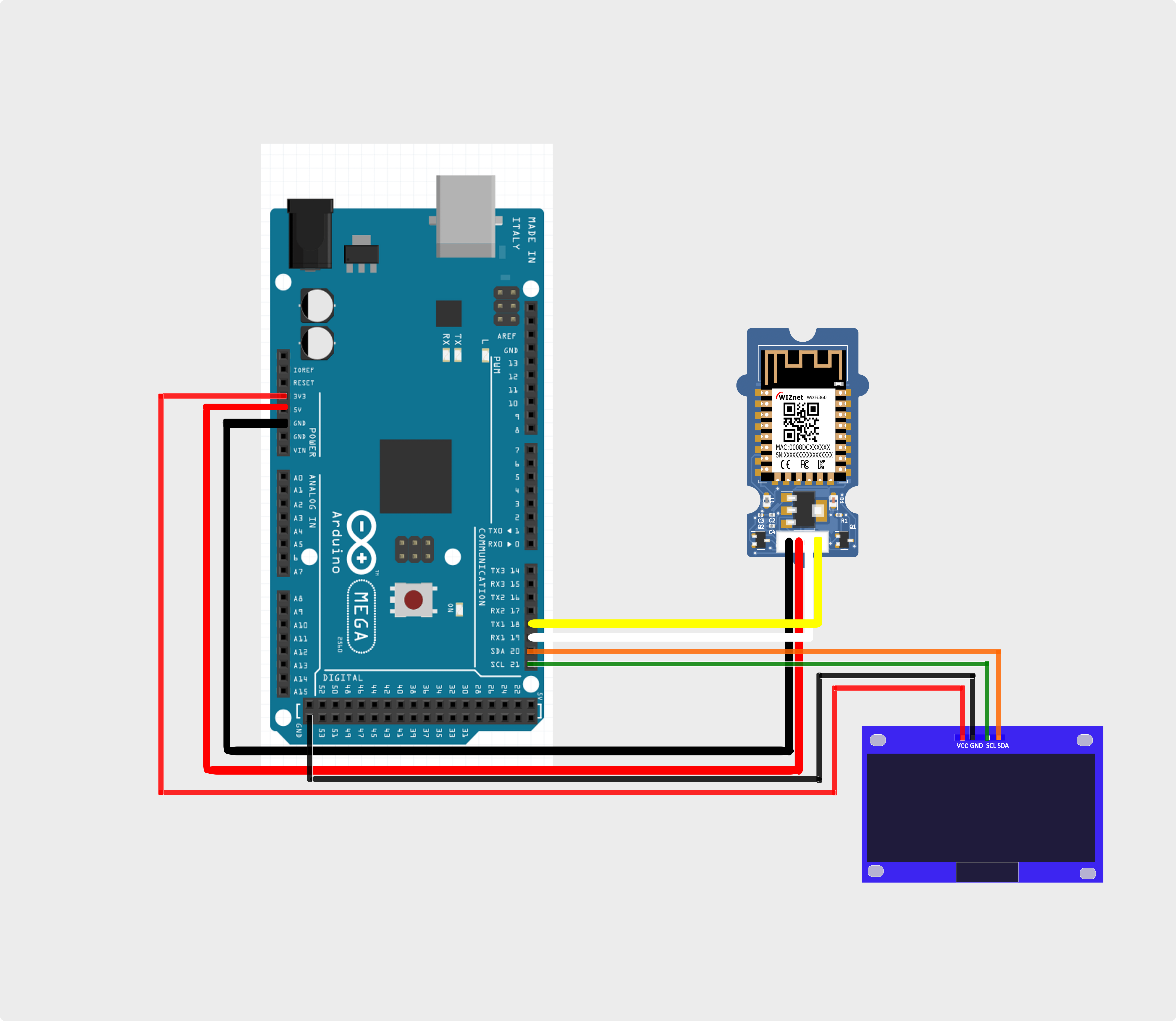
Hardware Connection :
Code :
/*
 Web Server Controlled Semaphore Device
 Green LED is indicates you are available and Red LED indicates you are busy.

 Libraries Required : WizFi360_arduino_library(https://github.com/Wiznet/WizFi360_arduino_library)


*/

#include "WizFi360.h"


#define AVAILABLE 1
#define BUSY 0

#define GREEN_LED 13
#define RED_LED 12

/* Baudrate */
#define SERIAL_BAUDRATE   115200
#define SERIAL1_BAUDRATE  115200

/* Wi-Fi info */
char ssid[] = "AM";       // your network SSID (name)
char pass[] = "12345678";   // your network password

int status = WL_IDLE_STATUS;  // the Wifi radio's status

int ledStatus = AVAILABLE;

WiFiServer server(80);

// use a ring buffer to increase speed and reduce memory allocation
RingBuffer buf(8);

void setup() {
  pinMode(RED_LED, OUTPUT);
  pinMode(GREEN_LED, OUTPUT);
  // initialize serial for debugging
  Serial.begin(SERIAL_BAUDRATE);
  // initialize serial for WizFi360 module
  Serial1.begin(SERIAL1_BAUDRATE);
  WiFi.init(&Serial1);

  // check for the presence of the shield
  if (WiFi.status() == WL_NO_SHIELD) {
    Serial.println("WiFi shield not present");
    // don't continue
    while (true);
  }

  // attempt to connect to WiFi network
  while (status != WL_CONNECTED) {
    Serial.print("Attempting to connect to WPA SSID: ");
    Serial.println(ssid);
    // Connect to WPA/WPA2 network
    status = WiFi.begin(ssid, pass);
  }
  Serial.println("You're connected to the network");
  printWifiStatus();
  digitalWrite(GREEN_LED, HIGH);  // Turn on GREEN LED  when Powered On
  // start the web server on port 80
  server.begin();
}

void loop() {
  WiFiClient client = server.available();  // listen for incoming clients
  if (client) {                               // if you get a client,
    Serial.println("New client");             // print a message out the serial port
    buf.init();                               // initialize the circular buffer
    while (client.connected()) {              // loop while the client's connected
      if (client.available()) {               // if there's bytes to read from the client,
        char c = client.read();               // read a byte, then
        buf.push(c);                          // push it to the ring buffer
        // printing the stream to the serial monitor will slow down
        // the receiving of data from the WizFi360 filling the serial buffer
        //Serial.write(c);
        // you got two newline characters in a row
        // that's the end of the HTTP request, so send a response
        if (buf.endsWith("\r\n\r\n")) {
          sendHttpResponse(client);
          break;
        }

        // Check to see if the client request was "GET /H" or "GET /L":
        if (buf.endsWith("GET /H")) {
          Serial.println("Turn led ON");
          ledStatus = AVAILABLE;
          digitalWrite(GREEN_LED, HIGH);
          digitalWrite(RED_LED, LOW);
        }
        else if (buf.endsWith("GET /L")) {
          Serial.println("Turn led OFF");
          ledStatus = BUSY;
          digitalWrite(GREEN_LED, LOW);    // turn the LED off by making the voltage LOW
          digitalWrite(RED_LED, HIGH);
        }
      }
    }
    // close the connection
    client.stop();
    Serial.println("Client disconnected");
  }
}

void sendHttpResponse(WiFiClient client) {
  // HTTP headers always start with a response code (e.g. HTTP/1.1 200 OK)
  // and a content-type so the client knows what's coming, then a blank line:
  client.println("HTTP/1.1 200 OK");
  client.println("Content-type:text/html");
  client.println();
  client.print("<!DOCTYPE HTML>\r\n");
          client.print("<html>\r\n");
          client.print("<h1>WizFiBuddy Semaphore Device</h1>\r\n");
          client.println("<style type=\"text/css\">body {font-size:1.7rem; font-family: Georgia; text-align:center; color: #333; background-color: #cdcdcd;} div{width:75%; background-color:#fff; padding:15px; text-align:left; border-top:5px solid #bb0000; margin:25px auto;}</style>");
          client.println("<meta name=\"viewport\" content=\"width=device-width, initial-scale=1\">");
  // the content of the HTTP response follows the header:
  client.print("Status : I am  ");
  if(ledStatus == AVAILABLE){
     client.print("Available");
  }
  else{
    client.print("Busy");
  }

  client.println("<br>");
  client.println("<br>");
  //adds styles
  client.println("<style type=\"text/css\">body {font-size:1.7rem; font-family: Georgia; text-align:center; color: #333; background-color: #cdcdcd;} div{width:75%; background-color:#fff; padding:15px; text-align:left; border-top:5px solid #bb0000; margin:25px auto;}</style>");
  client.println("<meta name=\"viewport\" content=\"width=device-width, initial-scale=1\">");
  client.println("</head>");
  client.println("<body>");
  client.println("<div>");
  client.println("* <a href=\"/H\">Available</a> <br>");
  client.println("* <a href=\"/L\">Busy</a> <br>");
  client.println("</form>");
  client.println("</form>");
  client.println("</div>");
  client.println("</body>");
  // The HTTP response ends with another blank line:
  client.println();
}

void printWifiStatus() {
  // print the SSID of the network you're attached to
  Serial.print("SSID: ");
  Serial.println(WiFi.SSID());
  // print your WiFi shield's IP address
  IPAddress ip = WiFi.localIP();
  Serial.print("IP Address: ");
  Serial.println(ip);
  // print where to go in the browser
  Serial.println();
  Serial.print("To see this page in action, open a browser to http://");
  Serial.println(ip);
  Serial.println();
}
Demo Video:
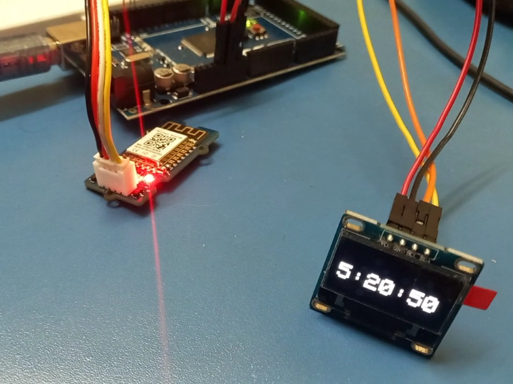
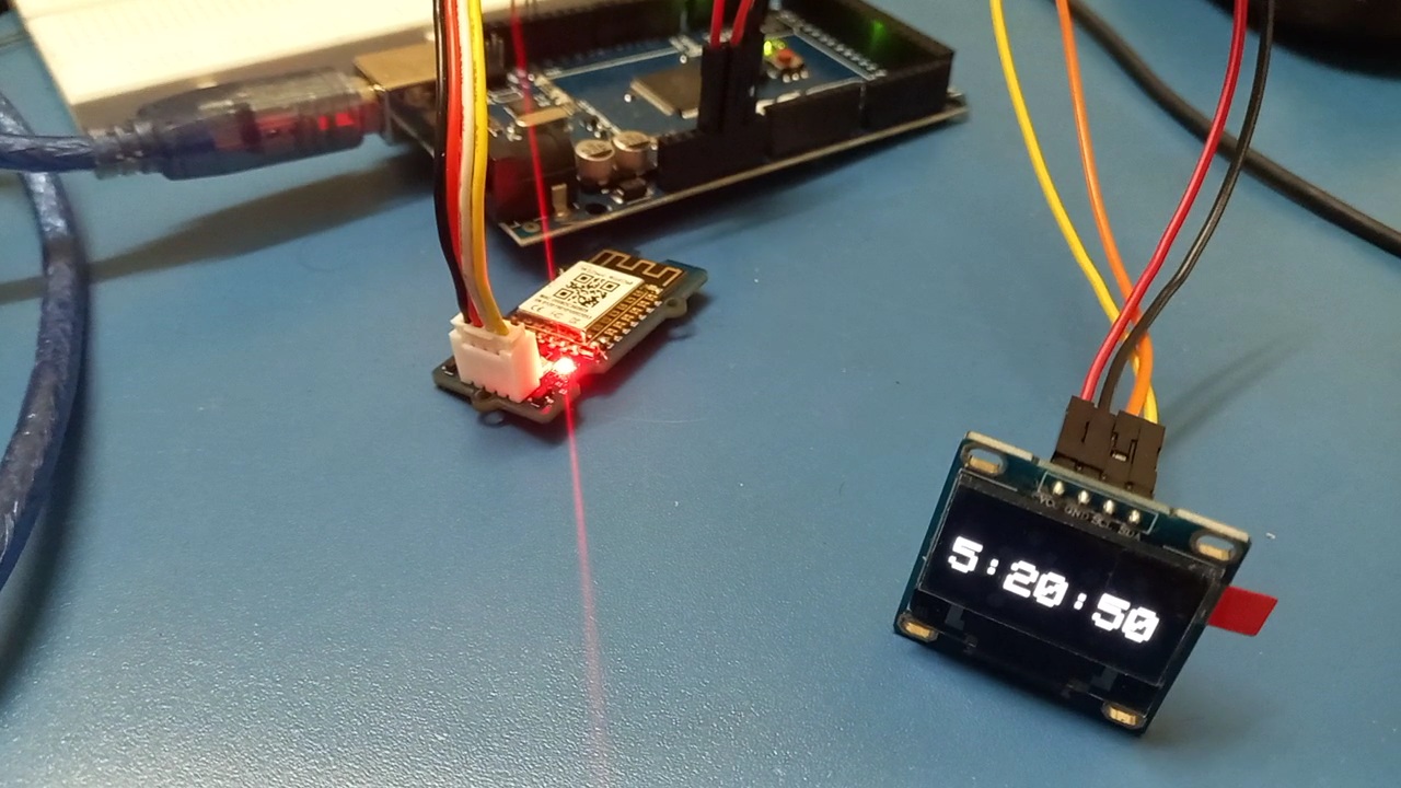
WizFi360+SNTP - Real Time Clock Display
Hardware Connection :
Code :
/*
  Get the time from a Network Time Protocol (NTP) time server and dispaly on OLED Screen.

 Required Libraries :
 1.Adafruit SSD1306 by Adafruit
 2.WizFi360_arduino_library  - https://github.com/Wiznet/WizFi360_arduino_library

*/

#include "WizFi360.h"
#include "WizFi360Udp.h"


#include <Wire.h>
#include <Adafruit_SSD1306.h>

// Change this offsetime based your time zone
#define OFFSET_TIME_ZONE 19800   // UTC+5:30 = 5.5*60*60 = 19800

#define SCREEN_WIDTH 128 // OLED display width,  in pixels
#define SCREEN_HEIGHT 64 // OLED display height, in pixels

// declare an SSD1306 display object connected to I2C
Adafruit_SSD1306 oled(SCREEN_WIDTH, SCREEN_HEIGHT, &Wire, -1);

/* Baudrate */
#define SERIAL_BAUDRATE   115200
#define SERIAL1_BAUDRATE  115200


/* Wi-Fi info */
char ssid[] = "AM";       // your network SSID (name)
char pass[] = "12345678";   // your network password

int status = WL_IDLE_STATUS;  // the Wifi radio's status

char timeServer[] = "time.nist.gov";  // NTP server
unsigned int localPort = 2390;        // local port to listen for UDP packets

const int NTP_PACKET_SIZE = 48;  // NTP timestamp is in the first 48 bytes of the message
const int UDP_TIMEOUT = 1000;    // timeout in milliseconds to wait for an UDP packet to arrive

byte packetBuffer[NTP_PACKET_SIZE]; // buffer to hold incoming and outgoing packets

// A UDP instance to let us send and receive packets over UDP
WiFiUDP Udp;

void setup() {
  // initialize serial for debugging
  Serial.begin(SERIAL_BAUDRATE);
  // initialize serial for WizFi360 module
  Serial1.begin(SERIAL1_BAUDRATE);

  // initialize WizFi360 module
  WiFi.init(&Serial1);

  // check for the presence of the shield
  if (WiFi.status() == WL_NO_SHIELD) {
    Serial.println("WiFi shield not present");
    // don't continue
    while (true);
  }

  // initialize OLED display with address 0x3C for 128x64
  if (!oled.begin(SSD1306_SWITCHCAPVCC, 0x3C)) {
    Serial.println(F("SSD1306 allocation failed"));
    while (true);
  }
  delay(2000);         // wait for initializing
  oled.clearDisplay(); // clear display
  // attempt to connect to WiFi network
  while ( status != WL_CONNECTED) {
    Serial.print("Attempting to connect to WPA SSID: ");
    Serial.println(ssid);
    // Connect to WPA/WPA2 network
    status = WiFi.begin(ssid, pass);
  }

  // you're connected now, so print out the data
  Serial.println("You're connected to the network");
  Udp.begin(localPort);
}

void loop() {
  sendNTPpacket(timeServer); // send an NTP packet to a time server
  // wait for a reply for UDP_TIMEOUT milliseconds
  unsigned long startMs = millis();
  while (!Udp.available() && (millis() - startMs) < UDP_TIMEOUT) {}
  if (Udp.parsePacket()) {
    // We've received a packet, read the data from it into the buffer
    Udp.read(packetBuffer, NTP_PACKET_SIZE);

    // the timestamp starts at byte 40 of the received packet and is four bytes,
    // or two words, long. First, esxtract the two words:

    unsigned long highWord = word(packetBuffer[40], packetBuffer[41]);
    unsigned long lowWord = word(packetBuffer[42], packetBuffer[43]);
    // combine the four bytes (two words) into a long integer
    // this is NTP time (seconds since Jan 1 1900):
    unsigned long secsSince1900 = highWord << 16 | lowWord;
    // now convert NTP time into everyday time:
    // Unix time starts on Jan 1 1970. In seconds, that's 2208988800:
    const unsigned long seventyYears = 2208988800UL;
    // subtract seventy years:
    unsigned long epoch = (secsSince1900 - seventyYears)+OFFSET_TIME_ZONE;
    oled.clearDisplay(); // clear display
    oled.setTextSize(3);          // text size
    oled.setTextColor(WHITE);     // text color
    oled.setCursor(0, 28);        // position to display
    // print the hour, minute and second:
    // UTC is the time at Greenwich Meridian (GMT)
    oled.print((epoch  % 86400L) / 3600);// print the hour (86400 equals secs per day)
    oled.print(':');

    if (((epoch % 3600) / 60) < 10) {
      // In the first 10 minutes of each hour, we'll want a leading '0'
      oled.print('0');
    }
    oled.print((epoch  % 3600) / 60);// print the minute (3600 equals secs per minute)
    oled.print(':');
    if ((epoch % 60) < 10) {
      // In the first 10 seconds of each minute, we'll want a leading '0'
      oled.print('0');
    }
    oled.print(epoch % 60);// print the second
  }
  oled.display();               // show on OLED
  // wait few millisecond before asking for the time again
  delay(800);
}

// send an NTP request to the time server at the given address
void sendNTPpacket(char *ntpSrv) {
  // set all bytes in the buffer to 0
  memset(packetBuffer, 0, NTP_PACKET_SIZE);
  // Initialize values needed to form NTP request
  // (see URL above for details on the packets)

  packetBuffer[0] = 0b11100011;   // LI, Version, Mode
  packetBuffer[1] = 0;     // Stratum, or type of clock
  packetBuffer[2] = 6;     // Polling Interval
  packetBuffer[3] = 0xEC;  // Peer Clock Precision
  // 8 bytes of zero for Root Delay & Root Dispersion
  packetBuffer[12]  = 49;
  packetBuffer[13]  = 0x4E;
  packetBuffer[14]  = 49;
  packetBuffer[15]  = 52;

  // all NTP fields have been given values, now
  // you can send a packet requesting a timestamp:
  Udp.beginPacket(ntpSrv, 123); //NTP requests are to port 123

  Udp.write(packetBuffer, NTP_PACKET_SIZE);

  Udp.endPacket();
}
Demo Video:
Thanks for reading , Happy Making !
-
Grove_WizFi360

-
Arduino Source Files
-
Connection diagram

-
Connection diagram