
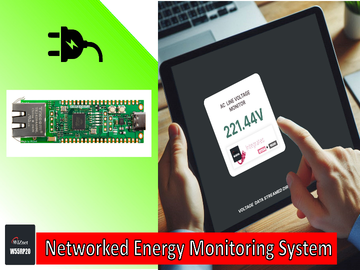
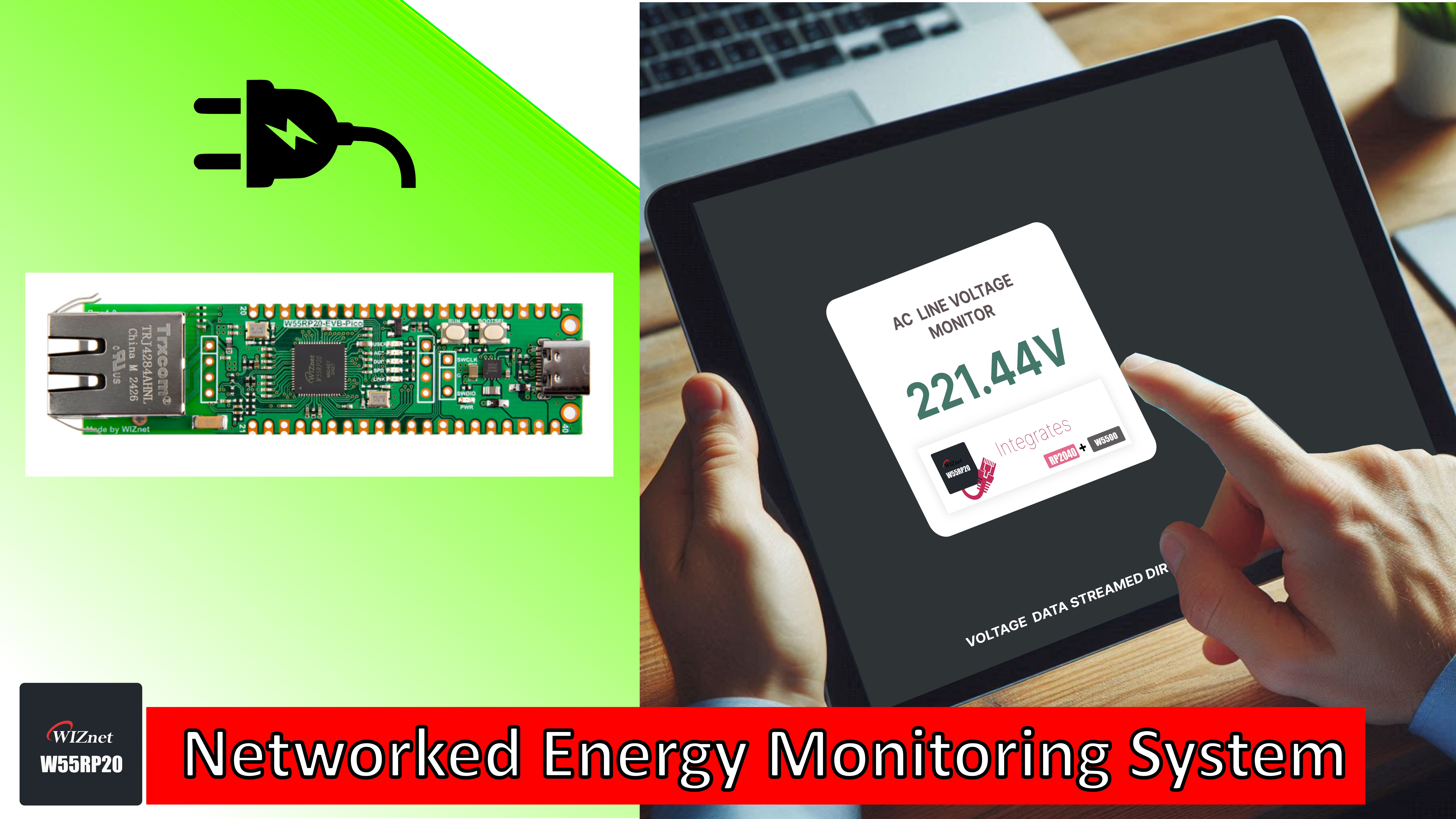
Networked Energy Monitoring System
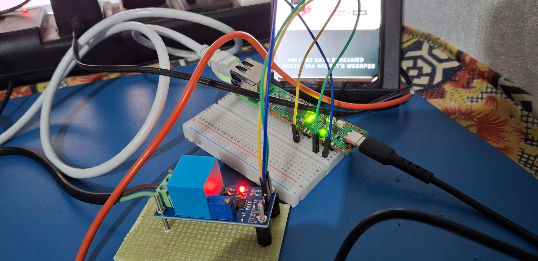
This project streams real-time AC voltage online via the W55RP20, unlocking potential for smart energy devices.
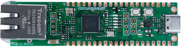
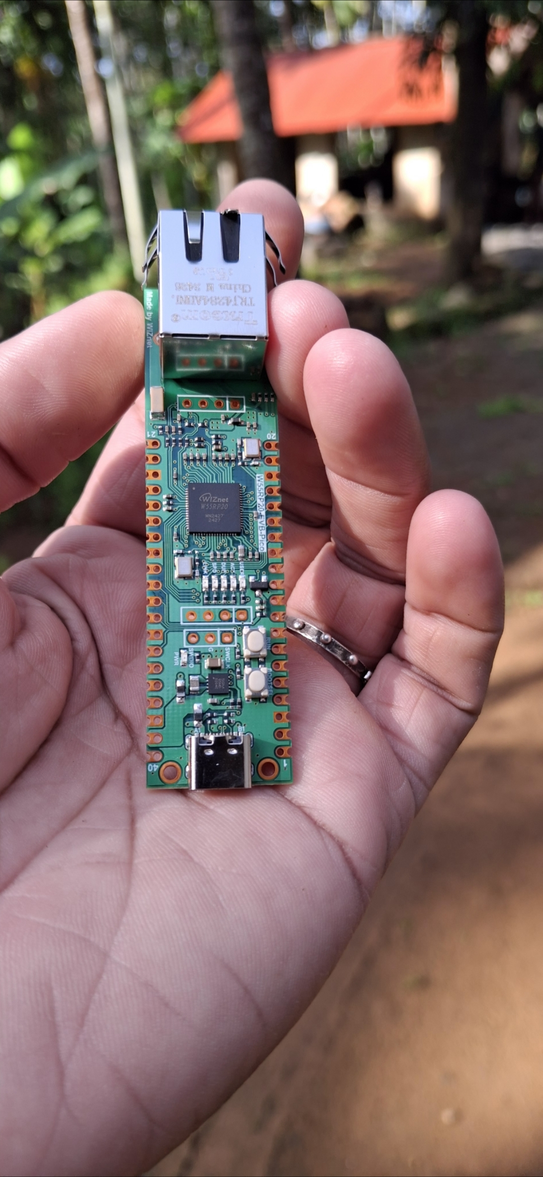
WIZnet - W55RP20-EVB-Pico
x 1
thonny.org - Thonny
x 1
Introduction:
This project demonstrates how real-time AC voltage can be monitored and sent over the internet using the W55RP20 controller. While it's a proof of concept for real-time data sharing, it opens the door to many possibilities. From smart energy devices to advanced energy management systems, this project can be expanded in countless ways.
Project Overview :
In this project, the ZMPT101B AC Voltage Sensor Module is used to measure AC voltage, while the W55RP20 Ethernet controller handles network connectivity. The real-time voltage data is posted via HTTP to a custom-hosted website, where it is displayed live. This forms the core of a scalable energy monitoring system, demonstrating how live energy data can be tracked and transmitted over the internet.
The W55RP20 combines the functions of the W5500 (a wired TCP/IP controller) and the RP2040 (used in the Raspberry Pi Pico), offering a powerful solution for seamless internet communication.
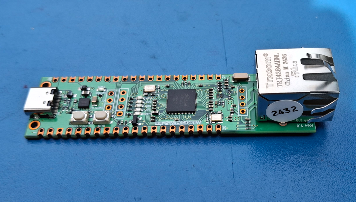
Take a look at the amazing W55RP20-EVB-PICO!
To learn more, check out the [W55RP20 documentation].
Key Features:
- Monitors real-time voltage using the ZMPT101B sensor
- Posts data to a web server using HTTP
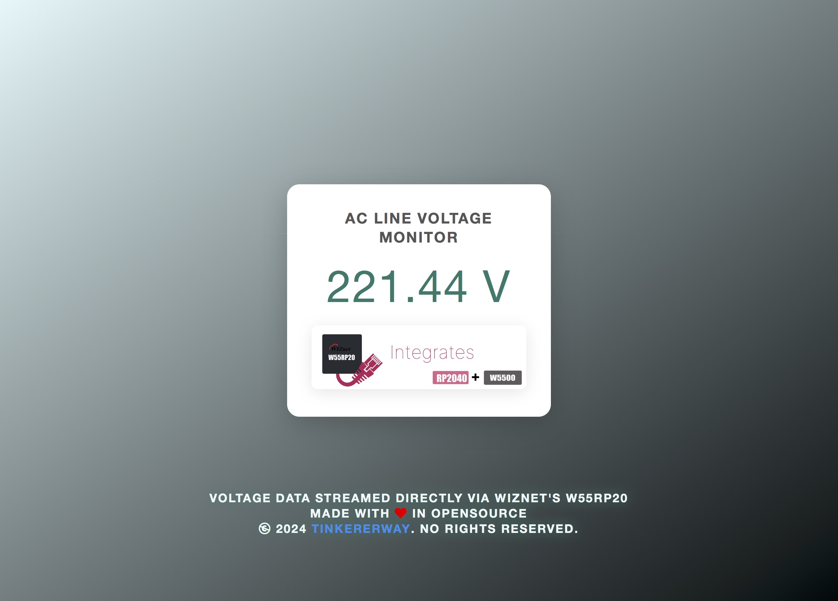
- Displays real-time values on a user-friendly interface. Check it out [here].
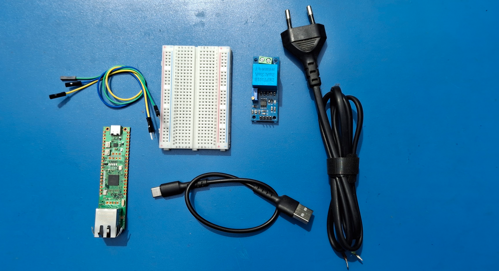
Components Needed:
| Name | Qty | Comment |
| WIZnet - W55Rp20-EVB-Pico | 1 | |
| ZMPT101B AC Voltage Sensor Module | 1 | |
| Jumper Wires | 3 | |
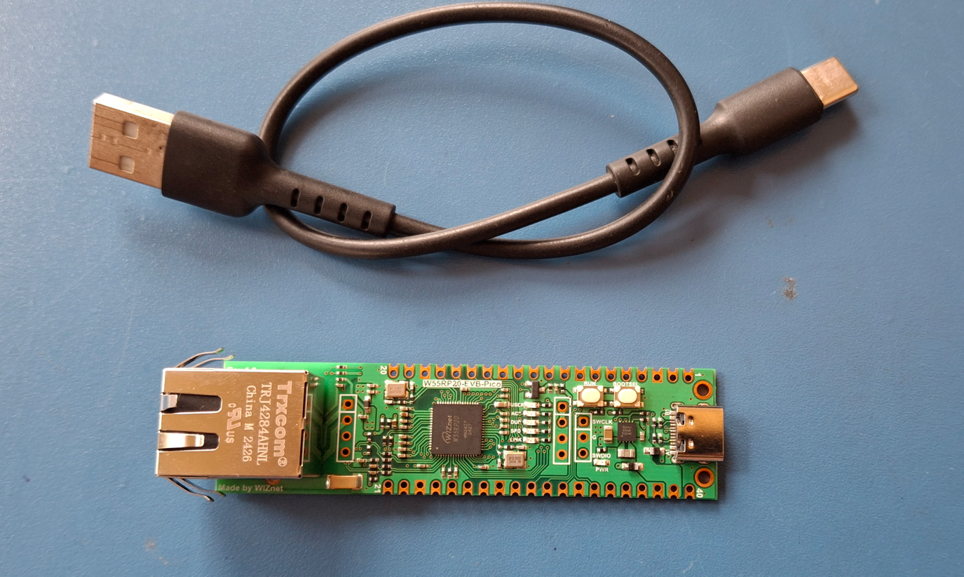
| USB-A to Type-C Cable | 1 | USB C port for power and data (and for reprogramming the Flash) |
| Ethernet Cables | 1 | |
| router | 1 | |
| 2 Pin Power Cord with Open Ended Cable | 1 | One end connects to line voltage, and the other connects to the AC voltage sensor. |
| Breadboard | 1 |
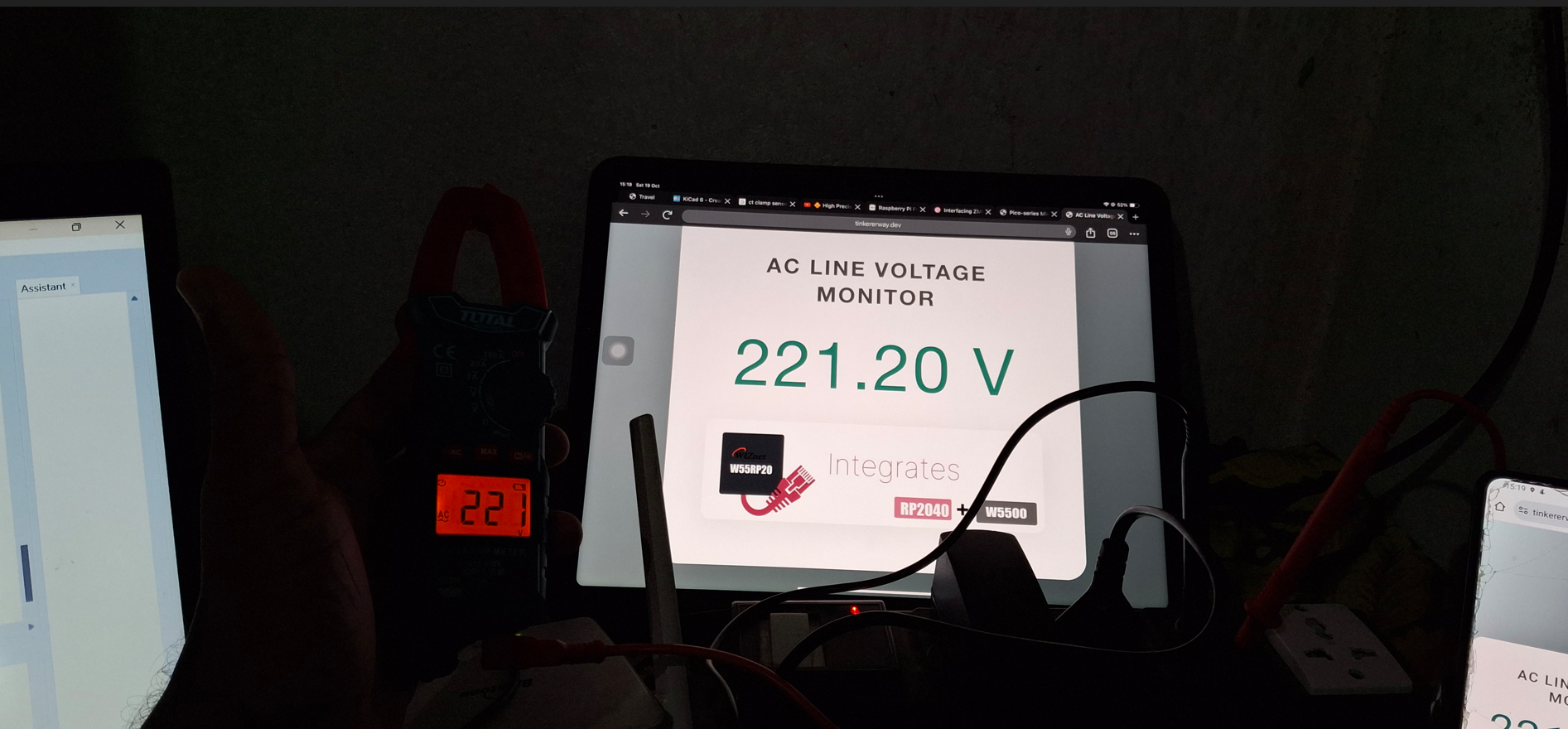
The live voltage is shown on my website, tinkererway.dev, for demonstration.The custom script manages the HTTP requests. Tinkererway.dev is my 'web tricorder'—a hub for tools that make life easier for those working with electronics and firmware.
Step-by-Step Guide:
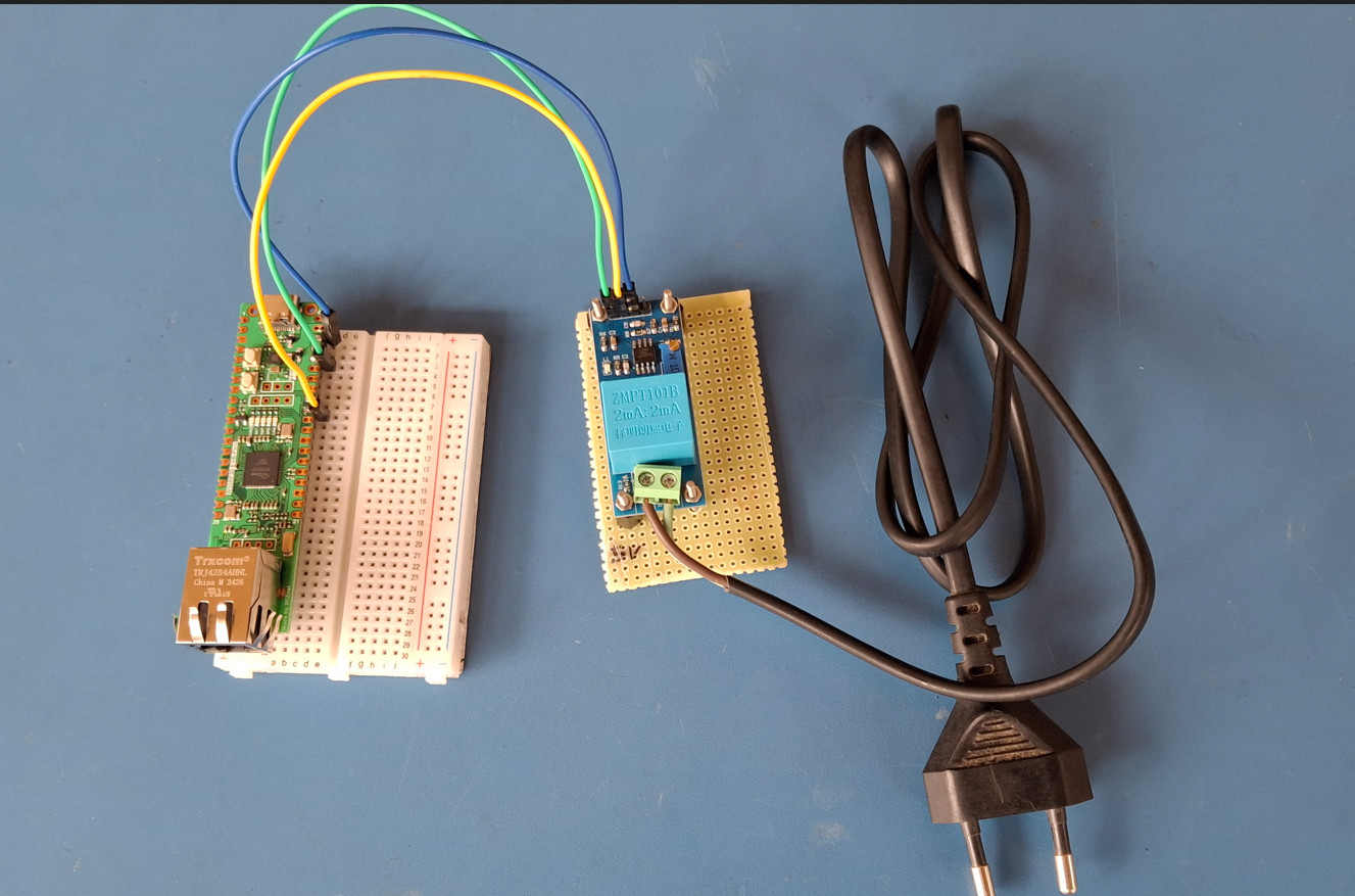
| Hardware Setup |
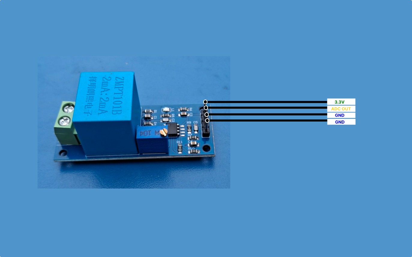
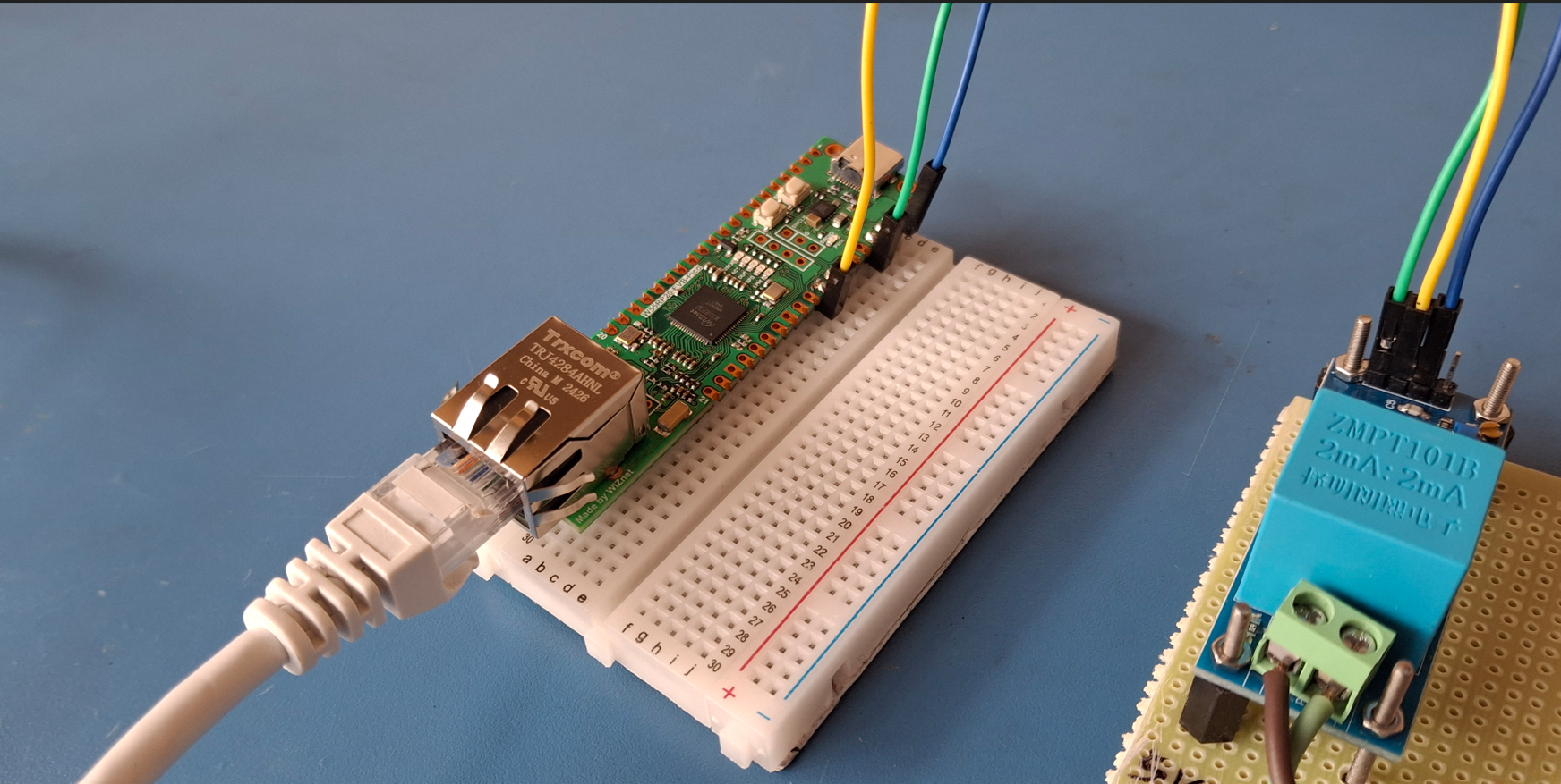
Connect the jumper cables from the ZMPT101B AC Voltage Sensor Module to the W55RP20-EVB-Pico as follows:
| ZMPT101B AC Voltage Sensor Module | W55Rp20-EVB-Pico |
| 3.3 V | 3V3(Pin 36) |
| GND | GND (Pins: 38, 33, 28, 23, 18, 13, 8, 3) |
| ADC OUT | GP26 (Pin 31) |
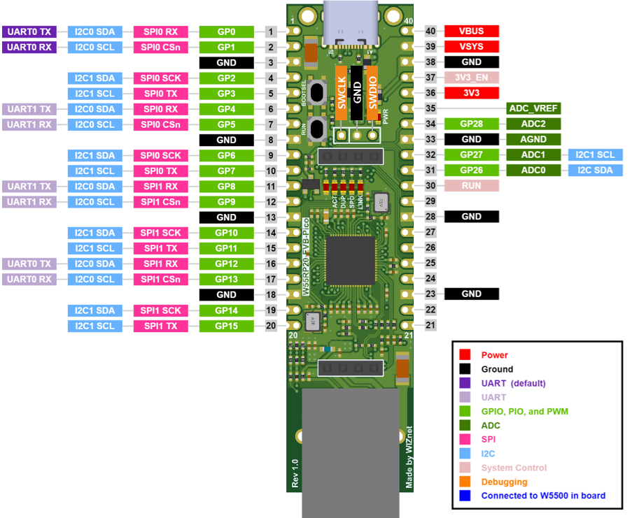
On the W55RP20, the SPI interface pins are connected internally to GPIO 20 to 25.
Note: Refer to the pinout diagrams for both modules to ensure accurate connections.
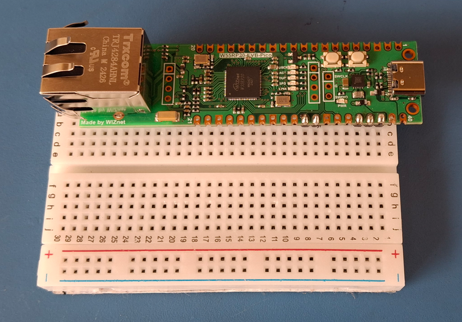
I soldered header pins to the W55RP20 Pico EVB and placed it on a breadboard. My first task was to accurately measure the AC voltage.
| Setting Up the Web Server |
The web server is responsible for handling incoming voltage data from the W55RP20. When the microcontroller sends a POST request containing the voltage value:
- Data Transmission: The device sends the voltage data as JSON to your server's specified endpoint.
- Processing Request: The PHP script receives this request, checks its validity, and processes the data accordingly.
- Data Storage: The script writes the received voltage data to a text file on the server, allowing for persistent storage and easy retrieval later.
- Feedback Loop: After processing the request, the server responds to the device, confirming whether the data was successfully received or if there were issues, ensuring a reliable communication loop.
| Software Development |
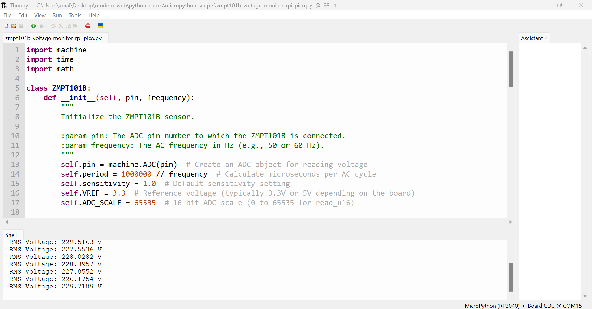
My first task was to accurately read the ADC values from the AC voltage sensor. For ease of development, I chose to use MicroPython with the Thonny IDE. As a quick test, I utilized one of my Raspberry Pi development boards to load the bootloader via Thonny and wrote code to read the voltage.
To ensure accuracy, I used my multimeter as a reference and adjusted the potentiometer on the ZMPT101B module accordingly.
The GitHub link directs you to the MicroPython code for reading AC voltage values.
import machine
import time
import math

class ZMPT101B:
    def __init__(self, pin, frequency):
        """
        Initialize the ZMPT101B sensor.

        :param pin: The ADC pin number to which the ZMPT101B is connected.
        :param frequency: The AC frequency in Hz (e.g., 50 or 60 Hz).
        """
        self.pin = machine.ADC(pin)  # Create an ADC object for reading voltage
        self.period = 1000000 // frequency  # Calculate microseconds per AC cycle
        self.sensitivity = 1.0  # Default sensitivity setting
        self.VREF = 3.3  # Reference voltage (typically 3.3V or 5V depending on the board)
        self.ADC_SCALE = 65535  # 16-bit ADC scale (0 to 65535 for read_u16)

    def set_sensitivity(self, value):
        """
        Set the sensitivity of the ZMPT101B sensor.

        :param value: Sensitivity value based on calibration.
        """
        self.sensitivity = value

    def get_zero_point(self):
        """
        Calculate the zero point (average center value of the waveform).

        :return: The average zero-point value over one AC cycle.
        """
        Vsum = 0  # Initialize the sum of voltage readings
        measurements_count = 0  # Initialize measurement count
        t_start = time.ticks_us()  # Start timing in microseconds

        # Sample values over one AC cycle
        while time.ticks_diff(time.ticks_us(), t_start) < self.period:
            Vsum += self.pin.read_u16()  # Read ADC value using read_u16()
            measurements_count += 1  # Increment the measurement count

        if measurements_count == 0:
            return 0  # Prevent division by zero in case no measurements were taken

        return Vsum // measurements_count  # Return average zero-point value

    def get_rms_voltage(self, loop_count):
        """
        Calculate RMS voltage over a set number of cycles.

        :param loop_count: The number of AC cycles to average for the RMS calculation.
        :return: The average RMS voltage over the specified cycles.
        """
        reading_voltage = 0.0  # Initialize total reading voltage

        # Loop for the specified number of cycles to get a better average RMS
        for _ in range(loop_count):
            zero_point = self.get_zero_point()  # Get the zero point for this cycle

            Vsum = 0  # Initialize the sum of squared voltages
            measurements_count = 0  # Initialize measurement count
            t_start = time.ticks_us()  # Start timing for one AC cycle

            # Collect data over one AC cycle
            while time.ticks_diff(time.ticks_us(), t_start) < self.period:
                Vnow = self.pin.read_u16() - zero_point  # Remove the zero-point offset
                Vsum += (Vnow * Vnow)  # Square the voltage for RMS calculation
                measurements_count += 1  # Increment the measurement count

            if measurements_count == 0:
                return 0.0  # Prevent division by zero in case no measurements were taken

            # Calculate RMS value
            rms = math.sqrt(Vsum / measurements_count)  # Calculate the square root of the average

            # Convert to actual voltage
            voltage = (rms / self.ADC_SCALE) * self.VREF * self.sensitivity
            reading_voltage += voltage  # Accumulate the voltage readings

        # Return the average RMS voltage over the specified cycles
        return reading_voltage / loop_count

# Example usage
adc_pin = 26  # Pin connected to the ZMPT101B (use your specific pin)
frequency = 50  # AC frequency (50 Hz for many regions, 60 Hz in others)

# Initialize the ZMPT101B sensor
zmpt = ZMPT101B(adc_pin, frequency)

# Optionally set the sensitivity (you should set this based on your calibration)
zmpt.set_sensitivity(500.00)  # Example sensitivity value, adjust based on your sensor

# Continuous RMS voltage reading loop
while True:
    rms_voltage = zmpt.get_rms_voltage(loop_count=50)  # Calculate RMS voltage over 50 cycles
    print("RMS Voltage:", rms_voltage, "V")  # Print the measured RMS voltage
    time.sleep(1)  # Delay for readability, adjust as necessary
The next step in my project was to explore the networking features of the W55RP20. For this, I used the bootloader available at the following link:
Release v1.0.0 · WIZnet-ioNIC/WIZnet-ioNIC-micropython
Mason's tutorial, titled "How to Build WIZnet-ioNIC-MicroPython," provided excellent guidance for testing the basic sample programs included. You can find these examples here:
A special shoutout to Mason for sharing valuable information on the WIZnet Maker website!
With all the test codes in place, I was ready to implement the actual logic. You can check out the code at this GitHub link.
import machine
import time
import math
from usocket import socket
from machine import Pin, WIZNET_PIO_SPI
import urequests
import network

class ZMPT101B:
    def __init__(self, pin, frequency):
        # Initialize ADC for reading voltage and calculate the period based on frequency
        self.pin = machine.ADC(pin)  # ADC object for reading voltage
        self.period = 1000000 // frequency  # Microseconds per AC cycle (for timing)
        self.sensitivity = 1.0  # Default sensitivity for voltage readings
        self.VREF = 3.3  # Reference voltage (usually 3.3V or 5V depending on the board)
        self.ADC_SCALE = 65535  # Scale for 16-bit ADC (0 to 65535 for read_u16)

    def set_sensitivity(self, value):
        """ Set the sensitivity of the ZMPT101B sensor. """
        self.sensitivity = value

    def get_zero_point(self):
        """ Calculate the zero point (average center value of the waveform). """
        Vsum = 0
        measurements_count = 0
        t_start = time.ticks_us()  # Start the timing in microseconds

        # Sample values over one AC cycle
        while time.ticks_diff(time.ticks_us(), t_start) < self.period:
            Vsum += self.pin.read_u16()  # Read ADC value using read_u16()
            measurements_count += 1

        if measurements_count == 0:
            return 0  # Prevent division by zero if no measurements were taken

        return Vsum // measurements_count  # Return average zero-point value

    def get_rms_voltage(self, loop_count):
        """ Calculate RMS voltage over a specified number of cycles (loop_count). """
        reading_voltage = 0.0

        # Loop for the specified number of cycles to get a better average RMS
        for _ in range(loop_count):
            zero_point = self.get_zero_point()  # Get zero point for current cycle

            Vsum = 0
            measurements_count = 0
            t_start = time.ticks_us()  # Start the timing for one AC cycle

            # Collect data over one AC cycle
            while time.ticks_diff(time.ticks_us(), t_start) < self.period:
                Vnow = self.pin.read_u16() - zero_point  # Remove zero-point offset
                Vsum += (Vnow * Vnow)  # Square the voltage for RMS calculation
                measurements_count += 1

            if measurements_count == 0:
                return 0.0  # Prevent division by zero if no measurements were taken

            # Calculate RMS value
            rms = math.sqrt(Vsum / measurements_count)

            # Convert RMS value to actual voltage
            voltage = (rms / self.ADC_SCALE) * self.VREF * self.sensitivity
            reading_voltage += voltage

        # Return the average RMS voltage over the specified cycles
        return reading_voltage / loop_count

# W5x00 Ethernet initialization
def w5x00_init():
    """ Initialize the W5x00 Ethernet chip for network communication. """
    # Set up SPI for the WIZNET chip
    spi = WIZNET_PIO_SPI(baudrate=31_250_000, mosi=Pin(23), miso=Pin(22), sck=Pin(21))  # W55RP20 PIO_SPI
    nic = network.WIZNET5K(spi, Pin(20), Pin(25))  # SPI, CS, reset pin
    nic.active(True)  # Activate the network interface

    # Static IP Configuration (can be switched to DHCP if needed)
    # Adjust the IP address and default gateway as necessary for your network setup
    nic.ifconfig(('192.168.18.20', '255.255.255.0', '192.168.18.1', '8.8.8.8'))

    # Wait until the device is connected to the network
    while not nic.isconnected():
        time.sleep(1)
        print("Connecting to network...")

    print('IP address:', nic.ifconfig())  # Print assigned IP address

# HTTP POST request to send the voltage
def send_voltage_data(voltage):
    """ Send the RMS voltage data to a specified server via HTTP POST request. """
    # URL to send data - it's a demo, so security is on vacation!
    # Please don't judge my lack of safety;so let’s keep this our little secret! :)
    base_url = 'https://tinkererway.dev/php/voltage_handler.php'
    data = {'voltage': str(voltage)}  # Construct the payload with the voltage value
    try:
        response = urequests.post(base_url, json=data)  # Send POST request
        if response.status_code == 200:
            print("Data sent successfully:", response.json())  # Print response if successful
        else:
            print("Failed to send data. Status code:", response.status_code)  # Print error status
        response.close()  # Close the response
    except Exception as e:
        print("Error during HTTP request:", e)  # Print error message if the request fails

def main():
    """ Main function to initialize components and continuously read and send voltage data. """
    # Initialize the W5x00 chip for network communication
    w5x00_init()

    # Initialize the ZMPT101B sensor on ADC pin 26 with 50 Hz AC frequency
    zmpt = ZMPT101B(pin=26, frequency=50)
    zmpt.set_sensitivity(500)  # Set sensor sensitivity based on calibration

    while True:
        # Get the RMS voltage value from the ZMPT101B sensor (e.g., averaging over 50 cycles)
        rms_voltage = zmpt.get_rms_voltage(loop_count=50)
        print("RMS Voltage:", rms_voltage, "V")  # Print the RMS voltage

        # Send the RMS voltage value over HTTP to the server
        send_voltage_data(rms_voltage)

        # Delay between readings (adjust as necessary)
        time.sleep(5)

if __name__ == "__main__":
    main()  # Run the main function when the script is executed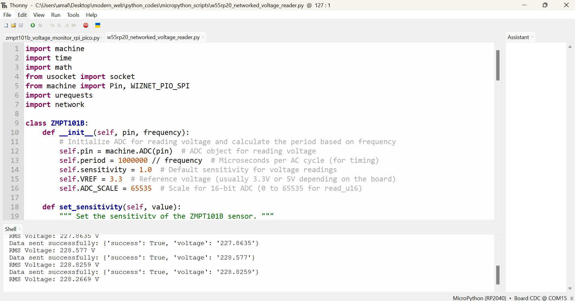
Limitless Possibilities
This tutorial shows how to send AC voltage data in real time, but this technology can be used for many other things, like:
- Smart Energy Devices: Connect this system to smart appliances to help them use energy more efficiently.
- Energy Management Systems: Use it to keep track of many devices or places, giving better control for homes or businesses.
- Automated Alerts: Set up alerts for unusual voltage levels so you can quickly fix problems, like turning off appliances during busy times.
- Renewable Energy Monitoring: Change the system to check renewable energy sources like solar panels or wind turbines, helping to balance power use with clean energy.
- Future Growth: Add more features in the future, like using data to predict energy needs or connecting to other smart devices.
Conclusion
This tutorial shows how to send real-time AC voltage data over the internet, giving quick insights into energy use. While this project is just a starting point, it opens the door to many smart energy applications. As our energy needs grow, real-time monitoring and better energy management will become more important, and the opportunities for new ideas are endless.
Check out this GitHub repository for future updates!

| Happy making, 73, DE Amal. |
-
w55rp20-based-energy-monitor

-
Demo Web Page: AC Line Voltage Monitor