
AI-driven IoT 3D Printer Motion & Status Tracker w/ Telegram
Ethernet HAT Contest winner project

Raspberry Pi - Raspberry Pi Pico
x 1
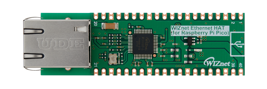
WIZnet - WIZnet Ethernet HAT
x 1

DFRobot - HuskyLens AI Camera
x 1
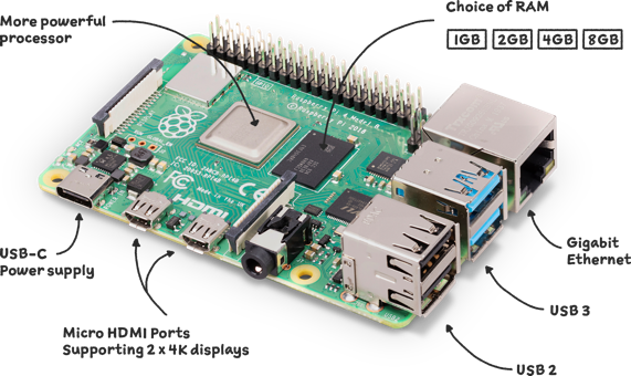
Raspberry Pi - Raspberry Pi 4
x 1

Creality - CR-6 SE 3D Printer
x 1
thonny.org - Thonny
x 1
Raspberry Pi - Raspbian
x 1

Adafruit - Circuitpython
x 1

Autodesk - Fusion 360
x 1

UltiMaker - Cura
x 1
microsoft - Visual Studio 2017
x 1
This project is Ethernet HAT contest winner and was moved from old maker site.
Story
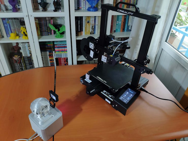
As you may have seen in my previous projects, I am utilizing a Creality CR-6 SE to print the 3D models I designed. During some of my prints, I encountered malfunctions related to the movements of my 3D printer four times while I was outside or not observing my printer. Generally, a non-watertight model, a problematic STL file, or an unstable printed part jammed or shifted one of the printer axes. When an axis is jammed or shifted, it causes faulty prints or impedes the printing process for troubleshooting.
Since the Creality CR-6 SE does not have Wi-Fi or an early warning system to monitor the printer motions and status, I decided to create a device to track the printer's lateral and vertical motions while printing so as to get informed of potential malfunctions related to the printer movements:
- X-Axis (the hot end)
- Y-Axis (the printer or heated bed)
- Z-Axis
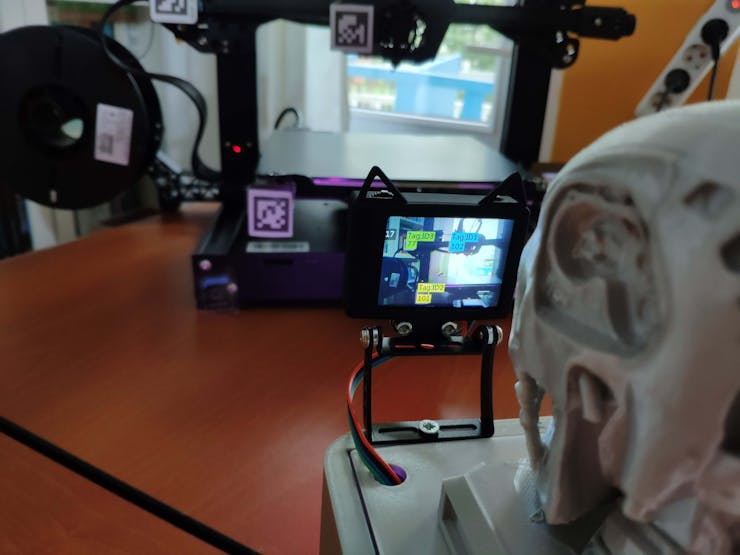
To endow this device with the ability to track X-axis, Y-axis, and Z-axis movements, I decided to employ the HuskyLens AI camera to recognize tags (AprilTags) denoting the axis motion. Since I was trying to develop a budget-friendly IoT device, I decided to utilize Raspberry Pi Pico to obtain and transfer the detected printer movements by the HuskyLens AI camera. Although there are various methods to connect Raspberry Pi Pico to the Internet, I chose to use the Pico-compatible WIZnet Ethernet HAT utilizing W5100S Hardwired TCP/IP CHIP. Since my printer is very close to my router, I did not encounter any issues regarding connecting the Ethernet cable or positioning the device.
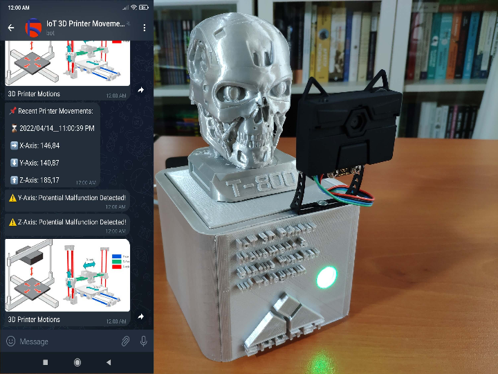
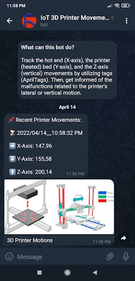
After connecting Raspberry Pi Pico to the Internet, I decided to utilize a Telegram bot to track the detected printer axis movements and get notified of malfunctions related to the printer motions. Since Telegram is a cross-platform cloud-based messaging service compatible with iOS and Android, the Telegram bot allows the user to monitor the printer movements and potential malfunctions on several devices. On Telegram, it is effortless to create bots with a command list unalike any other messaging application, which are special accounts that do not require an additional phone number to set up.
To be able to process the detected printer movements and send updates to the Telegram bot automatically, I developed a PHP web application. The web application obtains the printer movements from the Raspberry Pi Pico via HTTP POST requests, stores the received printer movements in the given MySQL database table, detects potential malfunctions related to the printer motions, and sends updates (also notifications) to the Telegram bot via the Telegram Bot API. After developing the web application, I employed a Raspberry Pi 3 to host a LAMP web server to run the application.
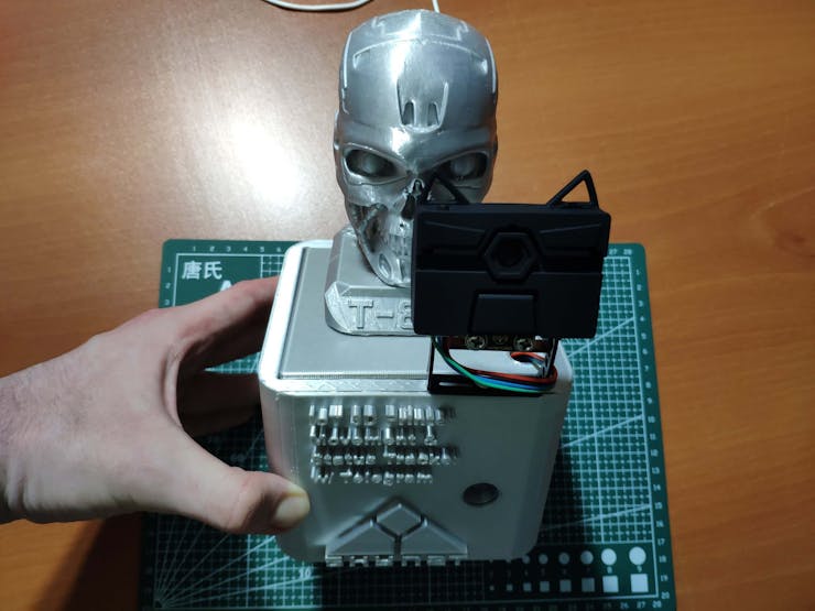
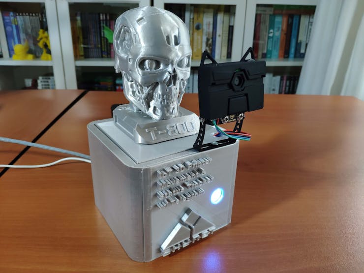
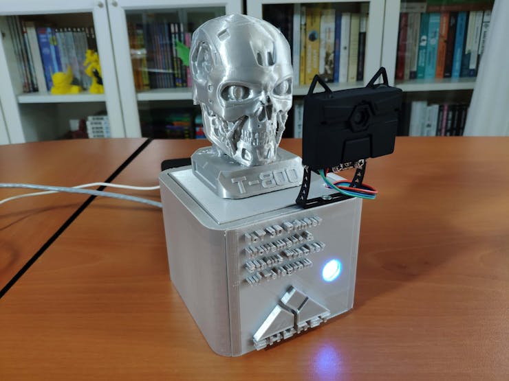
Lastly, to make the device as stylish and robust as possible while operating in my workshop, I designed a T-800 Terminator-inspired case with a removable top cover (3D printable).


Step 1: Designing and printing a T-800 Terminator-inspired case
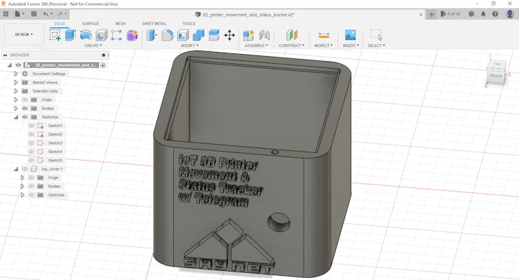
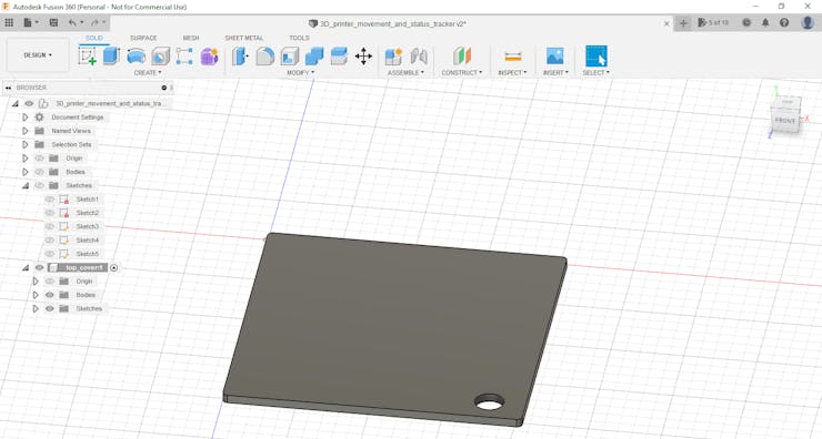
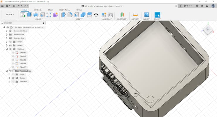
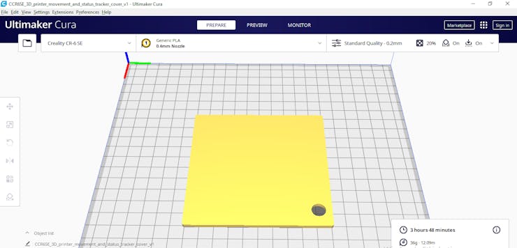
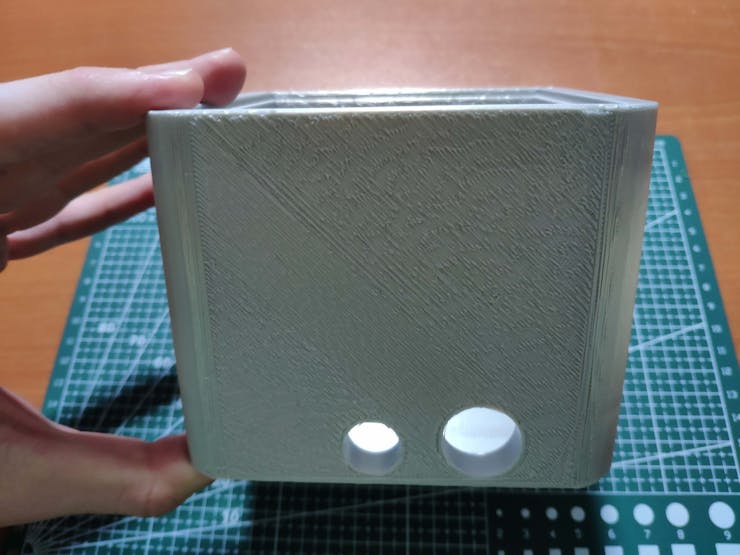
Since I wanted to place the device towards my FDM 3D printer while printing 3D models in my workshop, I decided to design a complementing metallic case to create a robust and sturdy mechanism operating flawlessly. To make device connections more accessible, I added a removable top cover to the case. Then, I got inspired by The Terminator to add a T-800 replica to the device since it aims to track the movements of the printer and detect potential malfunctions to eliminate them :)
I designed the main case and its removable top cover in Autodesk Fusion 360. You can download their STL files below.
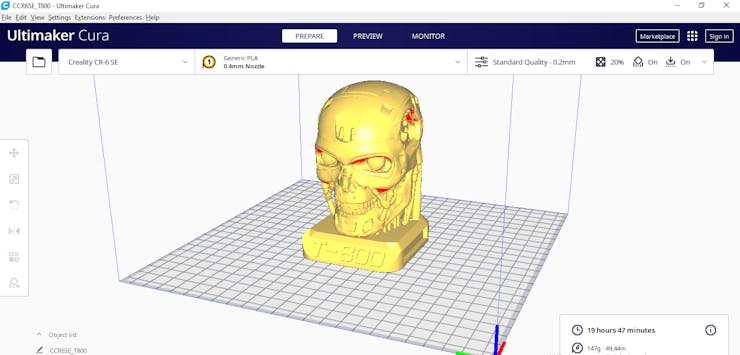
For the T-800 replica affixed to the removable top cover, I utilized this model from Thingiverse:
Then, I sliced all 3D models (STL files) in Ultimaker Cura.
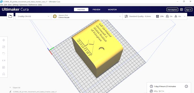
Since I wanted to create a solid structure for the metallic case with the removable top cover and emphasize the T-800 theme, I utilized this PLA filament:
- eSilk Silver
Finally, I printed all parts (models) with my Creality CR-6 SE 3D Printer. Although I am a novice in 3D printing, and it is my first FDM 3D printer, I got incredible results effortlessly with the CR-6 SE :)

Step 1.1: Assembling the case and making connections & adjustments
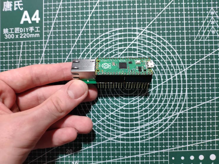
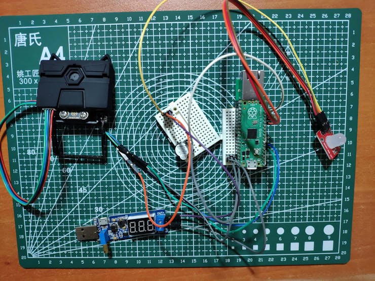
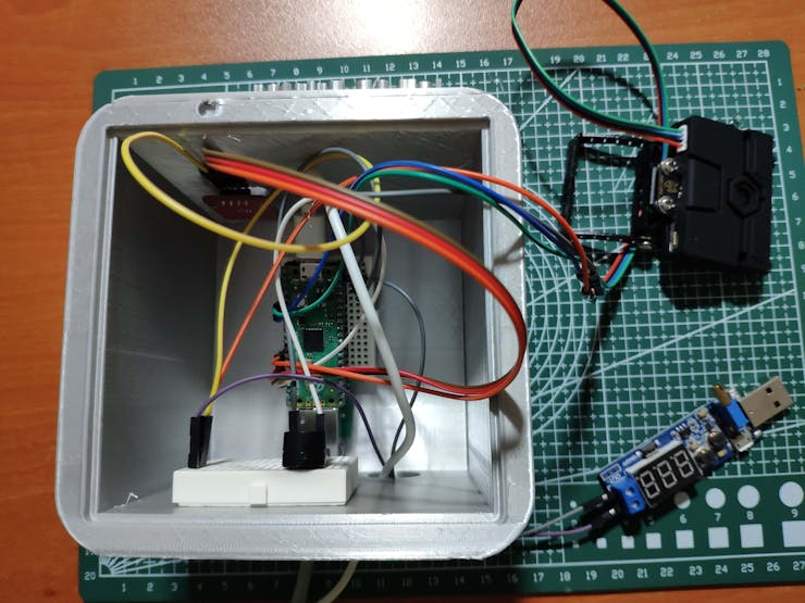
First of all, I soldered female pin headers (11mm long legs) to the WIZnet Ethernet HAT and male pin headers to the Raspberry Pi Pico in order to connect them to the mini breadboard as shown below.
To recognize the learned tags (AprilTags) so as to track the printer motions (X-axis, Y-axis, and Z-axis), I connected the HuskyLens AI camera to the Raspberry Pi Pico by utilizing the I2C protocol. Also, I added a 10mm common anode RGB LED module (Keyes) and a buzzer to indicate the outcomes of operating functions.
Since the Raspberry Pi Pico operates at 3.3V, it is not able to power the HuskyLens AI camera and the RGB LED at the same time sufficiently. Therefore, I employed an external power source to supply the mentioned components: To elicit stable supply voltage, I connected a USB buck-boost converter board to a Xiaomi power bank.
After completing sensor connections and adjustments on mini breadboards successfully, I made the breadboard connection points rigid by utilizing a hot glue gun.
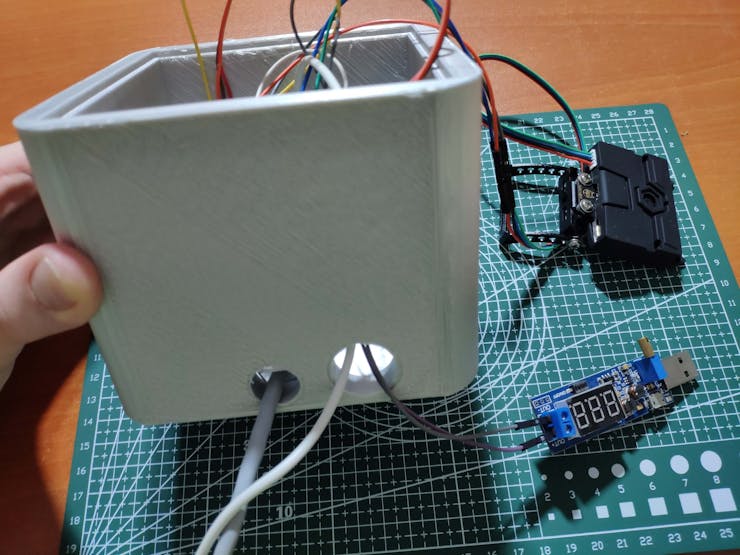
Then, after printing all 3D parts (models), I fastened all components to the main case and connected the LAN Ethernet cable from my router to the WIZnet Ethernet HAT. 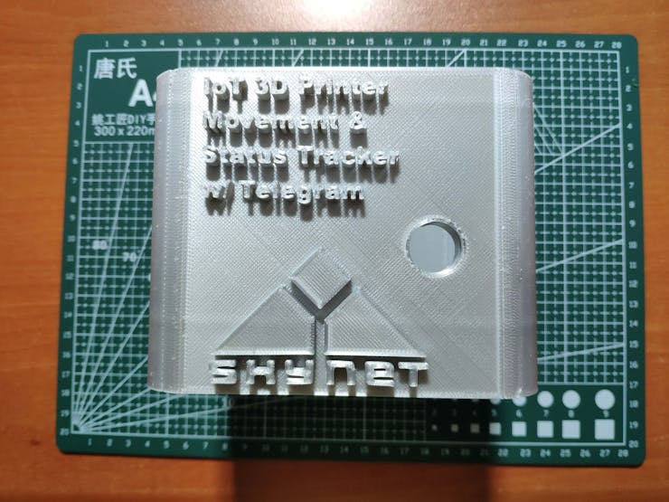
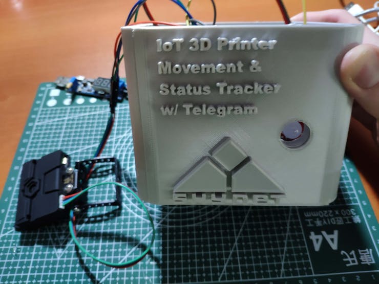
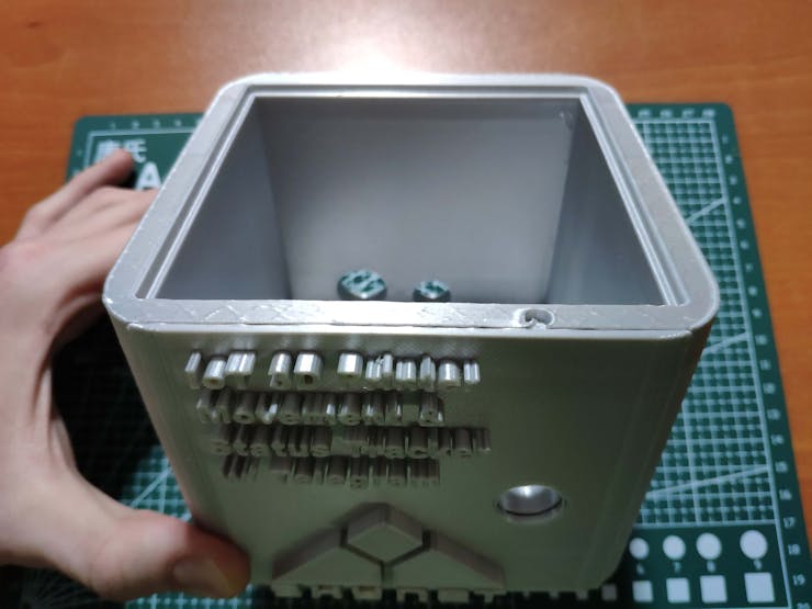
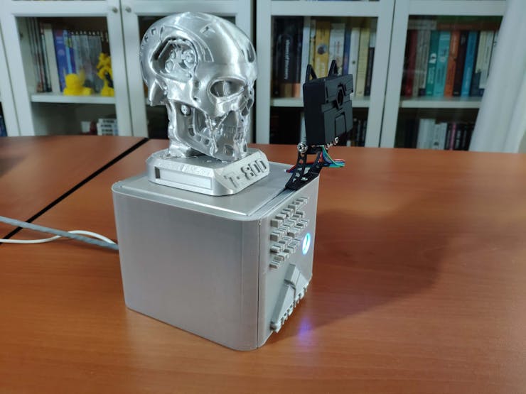
 Finally, I inserted the removable top cover in its slot on the main case and affixed the T-800 replica to the top of it via a hot glue gun. Also, I attached the HuskyLens AI camera to the case via a screw.
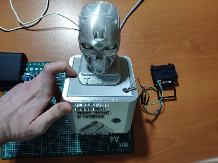
Step 2: Building a Telegram bot with BotFather
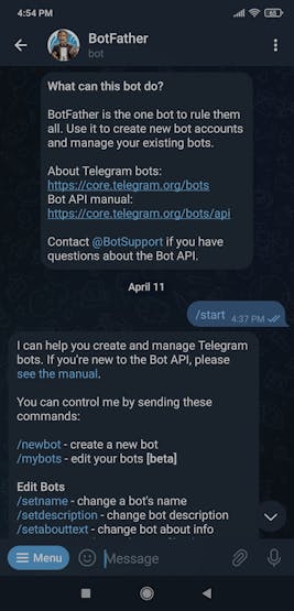
I utilized BotFather to create a Telegram bot for this project. BotFather is an official Telegram bot that lets the user create and manage bots on Telegram without any coding required.
#️⃣ First of all, open BotFather on Telegram and enter /start to view the available command list and manuals.
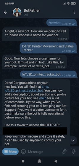
#️⃣ Use the /newbot command to create a new bot. Enter the name of your bot when BotFather asks you for a name. It is displayed in contact details and elsewhere.
IoT 3D Printer Movement and Status Tracker
#️⃣ Then, enter the username of your bot. Usernames are 5-32 characters long and are case insensitive but may only include Latin characters, numbers, and underscores. They must end in 'bot', e.g. 'tetris_bot' or 'TetrisBot'.
IoT_3D_printer_tracker_bot
#️⃣ After completing the steps above, BotFather generates an authorization token for your new bot. The authorization token is a string along the lines of 123456:ABC-DEF1234ghIkl-zyx57W2v1u123ew11 that is required to authorize the bot and send requests to the Telegram Bot API. Keep your token secure and store it safely.
 #️⃣ Also, you can change your bot's profile picture by using the /setuserpic command.
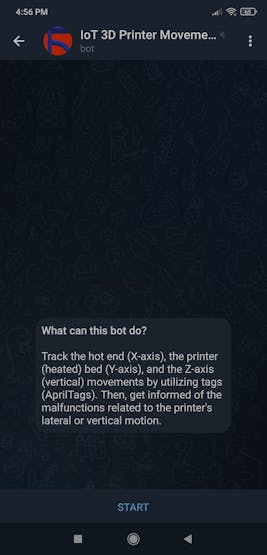
 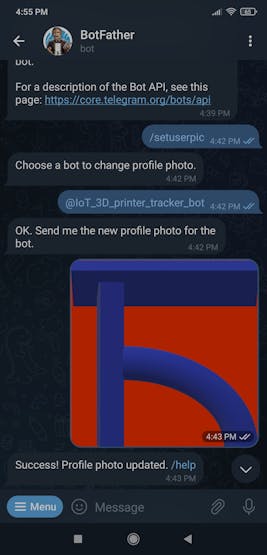 #️⃣ Finally, to add a description to your bot to be displayed when the chat is initialized, use the /setdescription command.
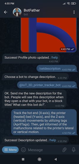
Since I wanted to get only printer movements updates from the Raspberry Pi Pico, I did not need to establish an SSL connection to set a webhook for the Telegram Bot API to send information back to the web application.
However, I needed to obtain the chat id to be able to send updates to the Telegram bot via the Telegram Bot API directly without establishing an SSL connection or setting up a webhook.
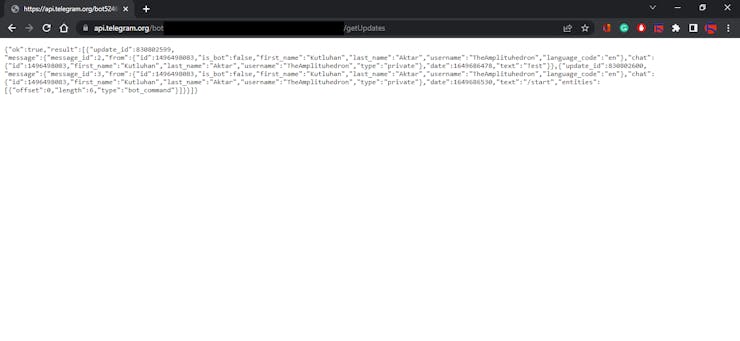
To get the chat id, I utilized the getUpdates method, which shows incoming updates using long polling and returns an array of Update objects.
#️⃣ Navigate to this web page by using your bot's authorization token:
https://api.telegram.org/bot<_token_>/getUpdates
#️⃣ Then, send a message to your bot and refresh the page. It will display an object list, including the chat id:
chat ➡ id ➡ 1496498083
Step 3: Developing a web application in PHP to send updates to the bot via the Telegram Bot API
After creating my Telegram bot successfully, I decided to develop a web application in PHP, named telegram_3D_printer_bot, so as to receive printer movements from the Raspberry Pi Pico, process them to detect malfunctions, and send updates to the Telegram bot.
As shown below, the web application consists of one file and has four parameters to create the required database table and obtain printer movements:
- index.php
Parameters:
- x_axis
- y_axis
- z_axis
- create_table
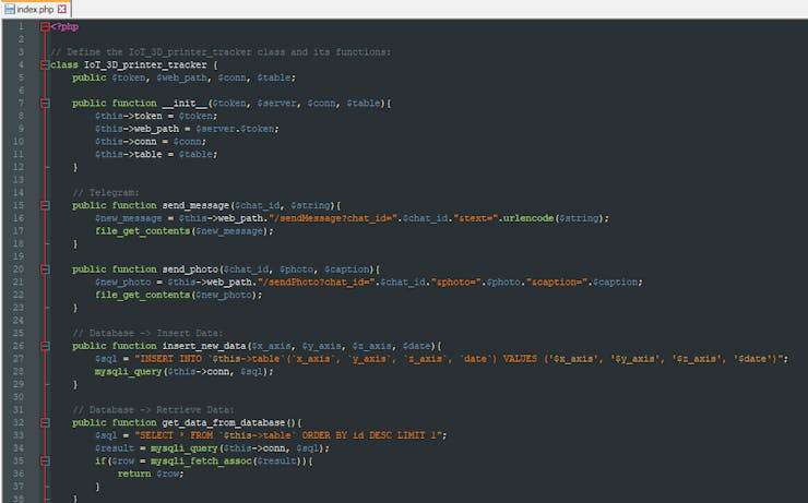
To run all functions successfully, I created a class named IoT_3D_printer_tracker. You can download and inspect the index.php file below.
⭐ In the __init__ function, define the required variables to execute the functions:
- token ➡ authorization token of the given Telegram bot
- web_path ➡ Telegram Bot API request server
- conn ➡ MySQL database connection settings
- table ➡ MySQL database table name
⭐ In the send_message function, the application sends the given text to the given bot via the Telegram Bot API by employing the bot's authorization token.
Syntax: https://api.telegram.org/bot<token>/sendMessage?chat_id=<chat_id>&text=<string>
⭐ In the send_photo function, the application sends the given picture to the given bot via the Telegram Bot API by employing the bot's authorization token.
Syntax: https://api.telegram.org/bot<token>/sendPhoto?chat_id=<chat_id>&photo=<link>&caption=<string>
public function __init__($token, $server, $conn, $table){
$this->token = $token;
$this->web_path = $server.$token;
$this->conn = $conn;
$this->table = $table;
}
// Telegram:
public function send_message($chat_id, $string){
$new_message = $this->web_path."/sendMessage?chat_id=".$chat_id."&text=".urlencode($string);
file_get_contents($new_message);
}
public function send_photo($chat_id, $photo, $caption){
$new_photo = $this->web_path."/sendPhoto?chat_id=".$chat_id."&photo=".$photo."&caption=".$caption;
file_get_contents($new_photo);
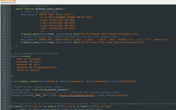
}⭐ In the insert_new_data function, append the given printer movement information to the given database table.
⭐ In the get_data_from_database function, retrieve the latest row stored in the given database table.
⭐ In the database_create_table function, create the required database table and insert the default data items as the first row into the recently created table.
// Database -> Insert Data:
	public function insert_new_data($x_axis, $y_axis, $z_axis, $date){
		$sql = "INSERT INTO `$this->table`(`x_axis`, `y_axis`, `z_axis`, `date`) VALUES ('$x_axis', '$y_axis', '$z_axis', '$date')";
		mysqli_query($this->conn, $sql);
	}

	// Database -> Retrieve Data:
	public function get_data_from_database(){
		$sql = "SELECT * FROM `$this->table` ORDER BY id DESC LIMIT 1";
		$result = mysqli_query($this->conn, $sql);
		if($row = mysqli_fetch_assoc($result)){
			return $row;
		}
	}

	// Database -> Create Table
	public function database_create_table(){
		// Create a new database table.
		$sql_create = "CREATE TABLE `$this->table`(
						id int AUTO_INCREMENT PRIMARY KEY NOT NULL,
						x_axis varchar(255) NOT NULL,
					    y_axis varchar(255) NOT NULL,
						z_axis varchar(255) NOT NULL,
						`date` varchar(255) NOT NULL
					   );";
		if(mysqli_query($this->conn, $sql_create)) echo("<br><br>Database Table Created Successfully!");
		// Insert the default data items as the first row into the given database table.
		$sql_insert = "INSERT INTO `$this->table`(`x_axis`, `y_axis`, `z_axis`, `date`) VALUES ('0,0', '0,0', '0,0', 'default')";
		if(mysqli_query($this->conn, $sql_insert)) echo("<br><br>Default Data Items Inserted Successfully!");
	}
⭐ Define the required MySQL database connection settings for Raspberry Pi and the printer_tracker object with its required parameters.
$server = array(
"name" => "localhost",
"username" => "root",
"password" => "bot",
"database" => "telegram3dprinter",
"table" => "entries"
);
$conn = mysqli_connect($server["name"], $server["username"], $server["password"], $server["database"]);
// Define the new 'printer_tracker' object:
$printer_tracker = new IoT_3D_printer_tracker();
$bot_token = "<_____________________>"; // e.g., 123456:ABC-DEF1234ghIkl-zyx57W2v1u123ew11
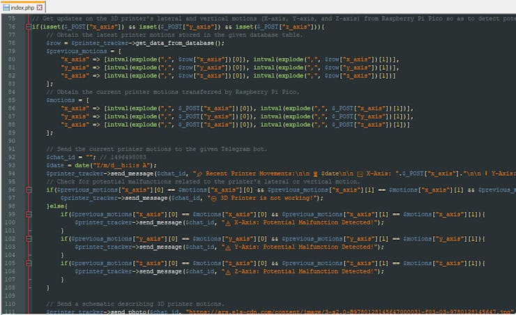
$printer_tracker->__init__($bot_token, "https://api.telegram.org/bot", $conn, $server["table"]);⭐ If the 3D printer's lateral and vertical motions (X-axis, Y-axis, and Z-axis) are transferred by the Raspberry Pi Pico via an HTTP POST request:
⭐ Obtain the latest printer motions stored in the given database table.
⭐ Get the current printer motions transferred by the Raspberry Pi Pico.
⭐ Send the current printer motions to the Telegram bot, including the date and time, with the given chat id.
Go to Step 2 to learn how to elicit the chat id.
⭐ Compare the latest (previous) and current printer motions to detect potential malfunctions related to the printer's lateral or vertical motion.
⭐ Then, inform the user of detected malfunctions, if any.
⭐ After every new update, send a schematic describing 3D printer motions to the Telegram bot.
⭐ Finally, append the current printer motions to the given database table.
if(isset($_POST["x_axis"]) && isset($_POST["y_axis"]) && isset($_POST["z_axis"])){
// Obtain the latest printer motions stored in the given database table.
$row = $printer_tracker->get_data_from_database();
$previous_motions = [
"x_axis" => [intval(explode(",", $row["x_axis"])[0]), intval(explode(",", $row["x_axis"])[1])],
"y_axis" => [intval(explode(",", $row["y_axis"])[0]), intval(explode(",", $row["y_axis"])[1])],
"z_axis" => [intval(explode(",", $row["z_axis"])[0]), intval(explode(",", $row["z_axis"])[1])]
];
// Obtain the current printer motions transferred by Raspberry Pi Pico.
$motions = [
"x_axis" => [intval(explode(",", $_POST["x_axis"])[0]), intval(explode(",", $_POST["x_axis"])[1])],
"y_axis" => [intval(explode(",", $_POST["y_axis"])[0]), intval(explode(",", $_POST["y_axis"])[1])],
"z_axis" => [intval(explode(",", $_POST["z_axis"])[0]), intval(explode(",", $_POST["z_axis"])[1])]
];
// Send the current printer motions to the given Telegram bot.
$chat_id = ""; // 1496498083
$date = date("Y/m/d__h:i:s A");
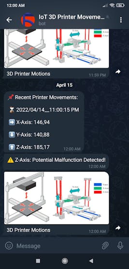
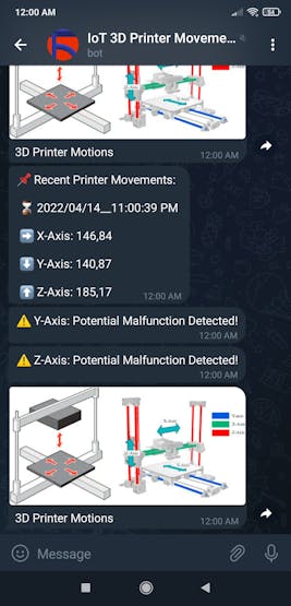
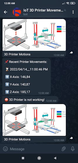
$printer_tracker->send_message($chat_id, "📌 Recent Printer Movements:\n\n ⌛ $date\n\n ➡️ X-Axis: ".$_POST["x_axis"]."\n\n ⬇️ Y-Axis: ".$_POST["y_axis"]."\n\n ⬆️ Z-Axis: ".$_POST["z_axis"]);
// Check for potential malfunctions related to the printer's lateral or vertical motion.
if($previous_motions["x_axis"][0] == $motions["x_axis"][0] && $previous_motions["x_axis"][1] == $motions["x_axis"][1] && $previous_motions["y_axis"][0] == $motions["y_axis"][0] && $previous_motions["y_axis"][1] == $motions["y_axis"][1] && $previous_motions["z_axis"][0] == $motions["z_axis"][0] && $previous_motions["z_axis"][1] == $motions["z_axis"][1]){
$printer_tracker->send_message($chat_id, "⛔ 3D Printer is not working!");
}else{
if($previous_motions["x_axis"][0] == $motions["x_axis"][0] && $previous_motions["x_axis"][1] == $motions["x_axis"][1]){
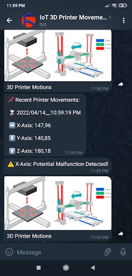
$printer_tracker->send_message($chat_id, "⚠️ X-Axis: Potential Malfunction Detected!");
}
if($previous_motions["y_axis"][0] == $motions["y_axis"][0] && $previous_motions["y_axis"][1] == $motions["y_axis"][1]){
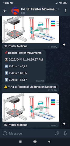
$printer_tracker->send_message($chat_id, "⚠️ Y-Axis: Potential Malfunction Detected!");
}
if($previous_motions["z_axis"][0] == $motions["z_axis"][0] && $previous_motions["z_axis"][1] == $motions["z_axis"][1]){
$printer_tracker->send_message($chat_id, "⚠️ Z-Axis: Potential Malfunction Detected!");
}
}
// Send a schematic describing 3D printer motions.
$printer_tracker->send_photo($chat_id, "https://ars.els-cdn.com/content/image/3-s2.0-B9780128145647000031-f03-03-9780128145647.jpg", "3D Printer Motions");
// Save the current printer motions to the given database table.
$printer_tracker->insert_new_data($_POST["x_axis"], $_POST["y_axis"], $_POST["z_axis"], $date);
echo("Data Saved and Transferred to the Telegram Bot Successfully!");
}else{
echo("Waiting for new data...");
}⭐ If requested, create the required database table (entries), including the default data items in the first row.
if(isset($_GET["create_table"]) && $_GET["create_table"] == "OK") $printer_tracker->database_create_table();
Step 4: Setting up a LAMP web server on Raspberry Pi
Since I decided to host my web application on a Raspberry Pi 3, I needed to set up a LAMP web server.
#️⃣ First of all, open a terminal window by selecting Accessories ➡ Terminal from the menu.
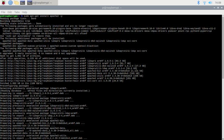
#️⃣ Then, install the apache2 package by typing the following command into the terminal and pressing Enter:
sudo apt-get install apache2 -y
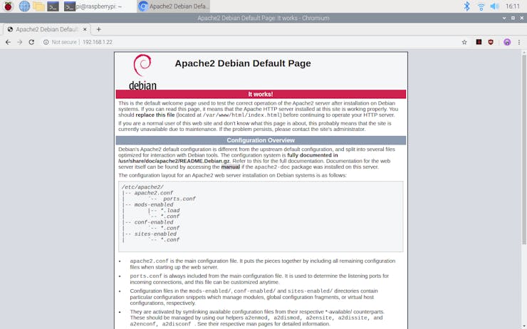
#️⃣ After installing the apache2 package successfully, open Chromium Web Browser and navigate to localhost so as to test the web server.
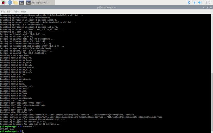
#️⃣ Then, enter the command below to the terminal to obtain the Raspberry Pi's IP address:
hostname -I
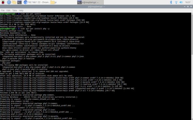
#️⃣ To install the latest package versions successfully, update the Pi. Then, download the PHP package by entering these commands below to the terminal:
sudo apt-get update
sudo apt-get install php -y
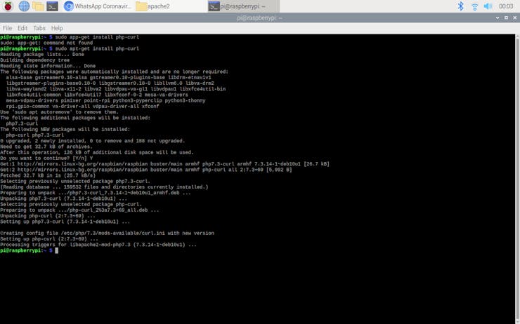
#️⃣ To be able to send requests from the web server to the Telegram Bot API, install the php-curl package:
sudo apt-get install php-curl
#️⃣ Then, restart the apache server to activate the installed packages on the web server:
sudo service apache2 restart
Step 4.1: Creating a MySQL database in MariaDB
Since I needed to log previous printer movements so as to detect potential malfunctions related to the printer's lateral and vertical motions, I also set up a MariaDB server on the Raspberry Pi 3.
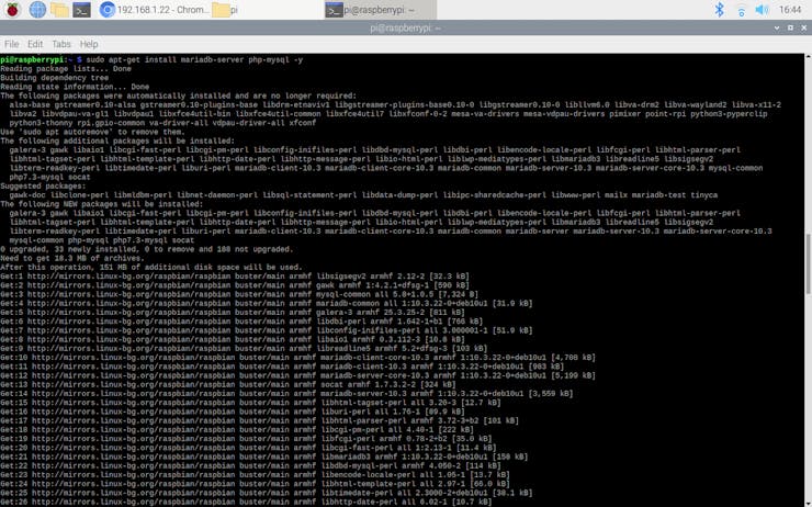
#️⃣ First of all, install the MariaDB (MySQL) server and PHP-MySQL packages by entering the following command into the terminal:
sudo apt-get install mariadb-server php-mysql -y
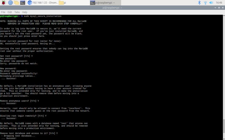
#️⃣ To create a new user, run the MySQL secure installation command in the terminal window:
sudo mysql_secure_installation
#️⃣ When requested, type the current password for the root user (enter for none). Then, press Enter.
#️⃣ Type in Y and press Enter to set the root password.
#️⃣ Type in bot at the New password: prompt, and press Enter.
#️⃣ Type in Y to remove anonymous users.
#️⃣ Type in Y to disallow root login remotely.
#️⃣ Type in Y to remove the test database and its access permissions.
#️⃣ Type in Y to reload privilege tables.
#️⃣ After successfully setting the MariaDB server, the terminal prints: All done! Thanks for using MariaDB!
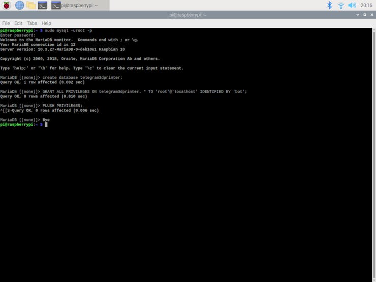
#️⃣ Finally, to create a new database in the MariaDB server, run the MySQL interface in the terminal:
sudo mysql -uroot -p
#️⃣ Then, enter the recently changed root password - bot.
#️⃣ When the terminal shows the MariaDB [(none)]> prompt, create the new database (telegram3dprinter) by utilizing these commands below:
create database telegram3dprinter;

GRANT ALL PRIVILEGES ON telegram3dprinter.* TO 'root'@'localhost' IDENTIFIED BY 'bot';

FLUSH PRIVILEGES;
#️⃣ Press Ctrl + D to exit the MariaDB [(none)]> prompt.
Step 4.2: Setting and running the web application on Raspberry Pi
As discussed above, I set up a LAMP web server on my Raspberry Pi 3 to run the web application, but you can run it on any server as long as it is a PHP server.
#️⃣ First of all, install and extract the telegram_3D_printer_bot.zip folder.
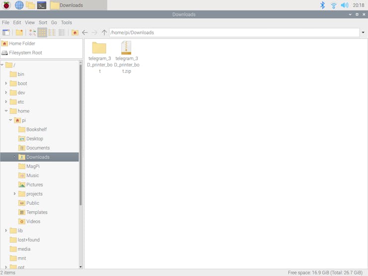
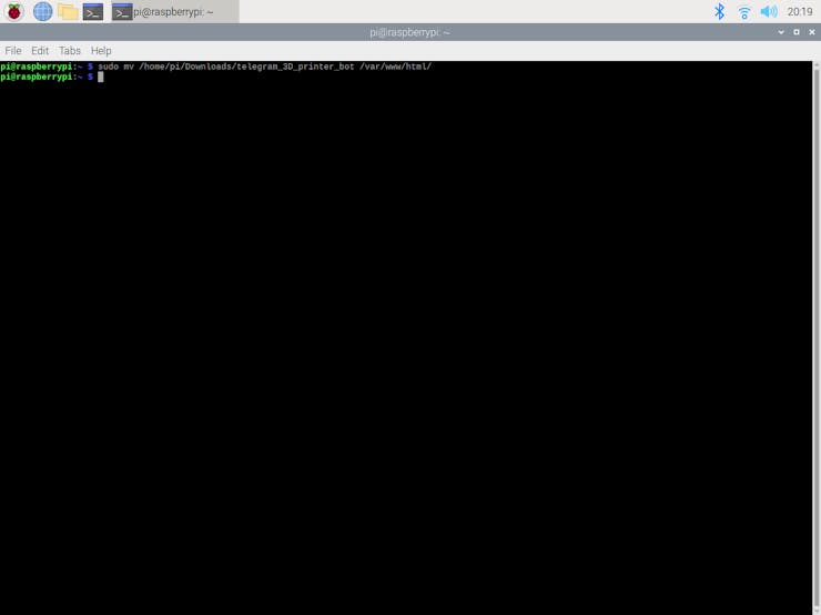
#️⃣ Then, move the application folder (telegram_3D_printer_bot) to the Apache server (/var/www/html) by using the terminal since the Apache server is a protected location.
sudo mv /home/pi/Downloads/telegram_3D_printer_bot /var/www/html/
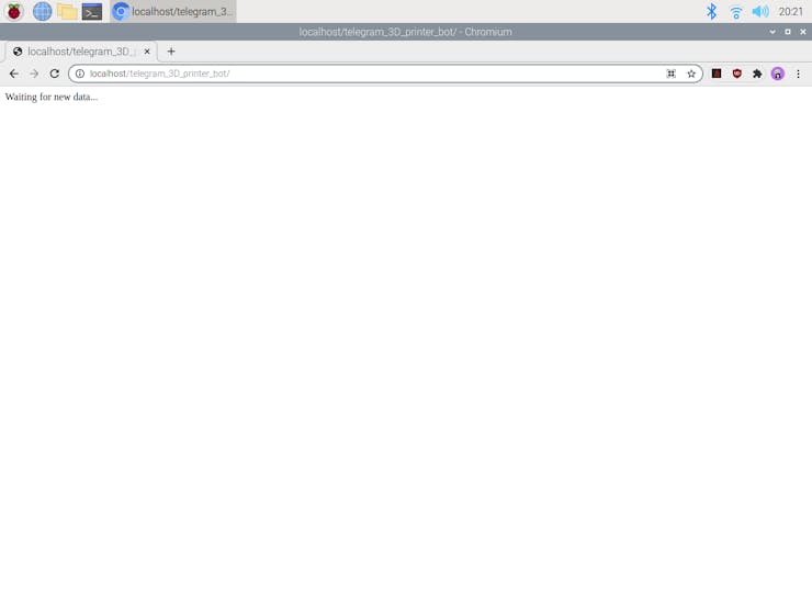
⭐ If the web application did not receive the printer movements from the Raspberry Pi Pico via an HTTP POST request, it prints: Waiting for new data...
⭐ Otherwise, the web application prints: Data Saved and Transferred to the Telegram Bot Successfully!
localhost/telegram_3D_printer_bot/
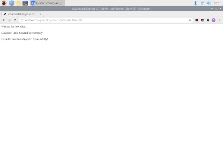
⭐ If the create_table parameter is set as OK, the web application creates the requested database table and inserts the default data items as the first row into the recently created table. Then, it prints:
Database Table Created Successfully!
Default Data Items Inserted Successfully!
localhost/telegram_3D_printer_bot/?create_table=OK
Step 5: Updating and setting up the HuskyLens AI Camera
HuskyLens AI camera is capable of transferring the detection results of its built-in functions via the UART (serial) or I2C protocol. I decided to utilize the I2C protocol since it is much easier to get information with the I2C protocol on the Raspberry Pi Pico.
However, before proceeding with the following steps, I needed to update the HuskyLens firmware with the latest version to get more accurate results.
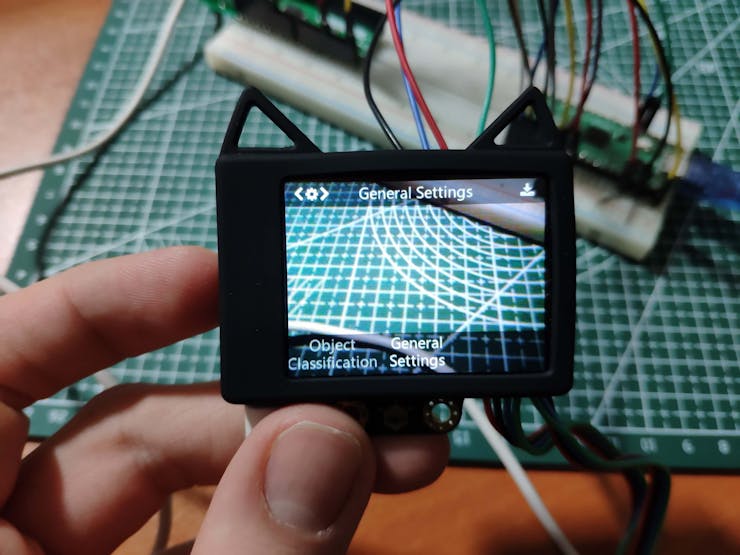
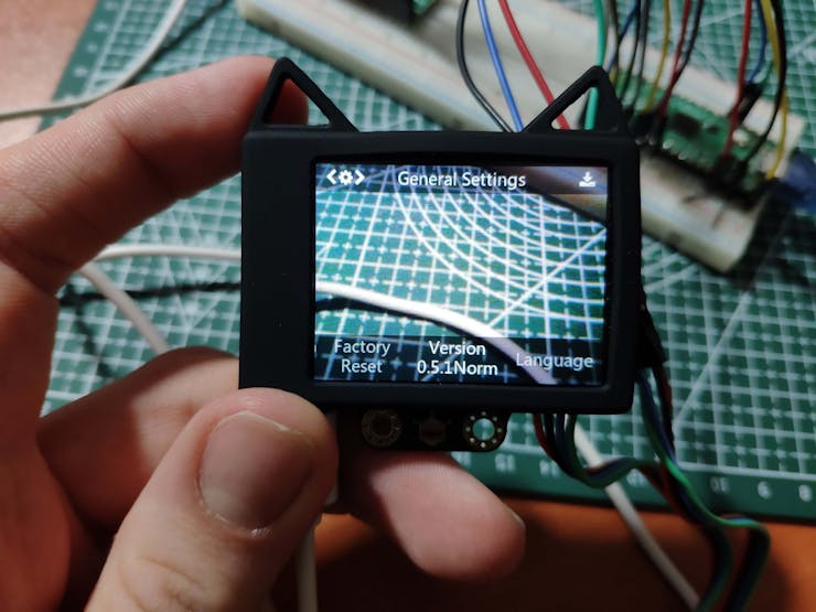
#️⃣ After connecting the HuskyLens AI camera to the computer (Windows) via a micro USB cable, click the General Settings to view the version number.
#️⃣ Then, install the HuskyLens Uploader for Windows from here. If requested, you may need to install the CP2102N chip driver from here.
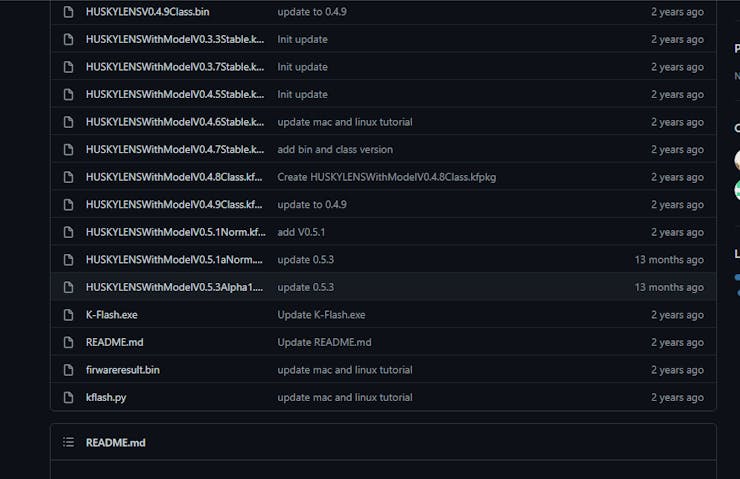
#️⃣ Search for the latest firmware version here, currently V0.5.3Alpha1, and download it.
 #️⃣ Run the HuskyLens Uploader, a small black CMD window will pop up first, and after a while, the interface window will appear: Then, click the Select File button to upload the latest firmware file.
 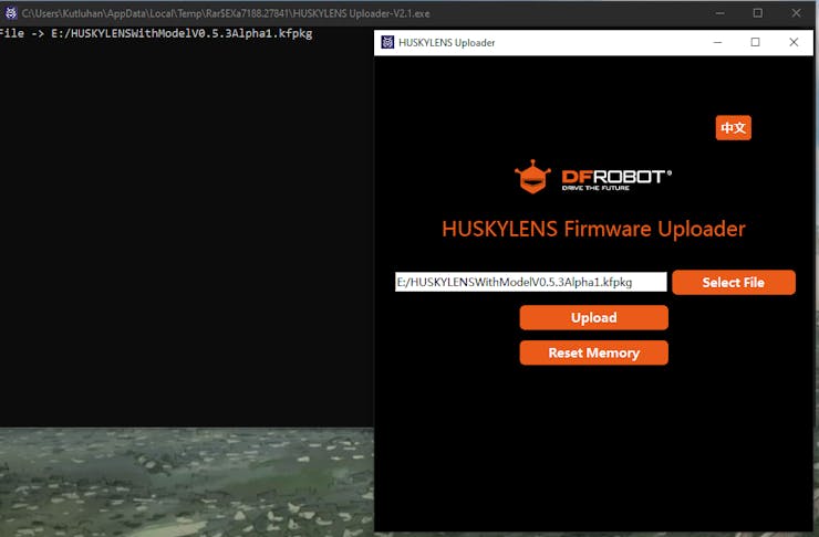 #️⃣ Finally, click the Upload button and wait about 5 minutes until the firmware is upgraded successfully.
 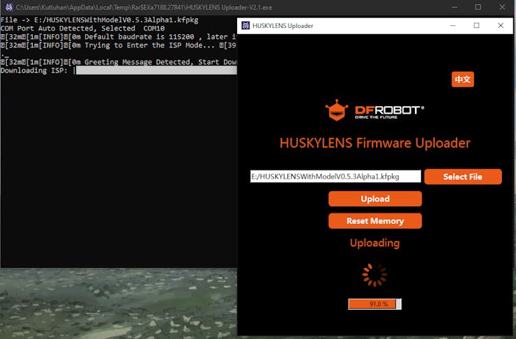 After following the steps above, HuskyLens should display the upgraded version number on the settings menu.
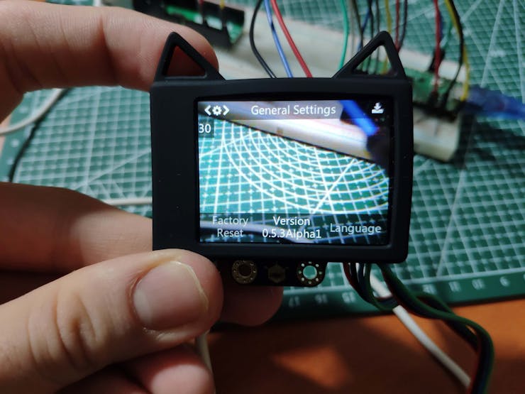
Step 5.1: Detecting tags (AprilTags) w/ HuskyLens
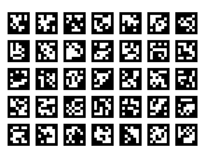
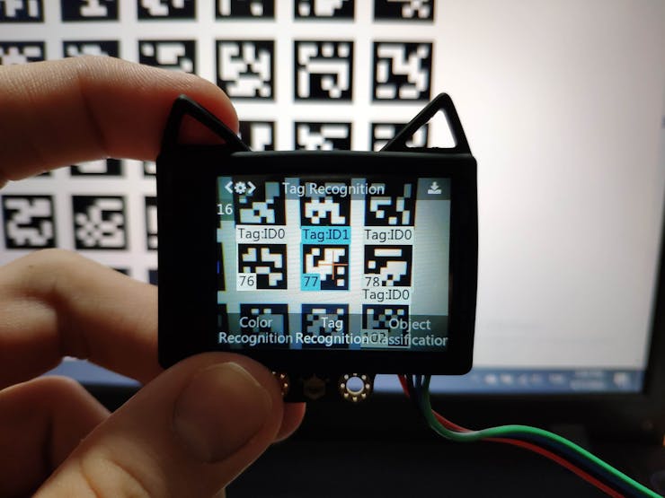
After upgrading the firmware, I trained HuskyLens to learn three different AprilTags from the figure below for each printer axis (X-axis, Y-axis, and Z-axis) so as to track the printer's lateral and vertical motions.
 #️⃣ First of all, switch to the Tag Recognition mode.
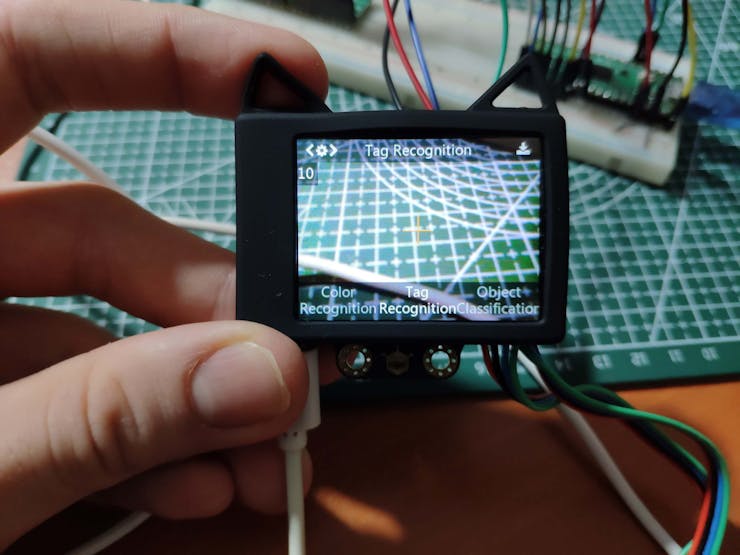
#️⃣ Since the default setting is to learn a single tag, long press the function button to open the parameter setting interface.
#️⃣ Then, switch to the Learn Multiple parameter and activate it.
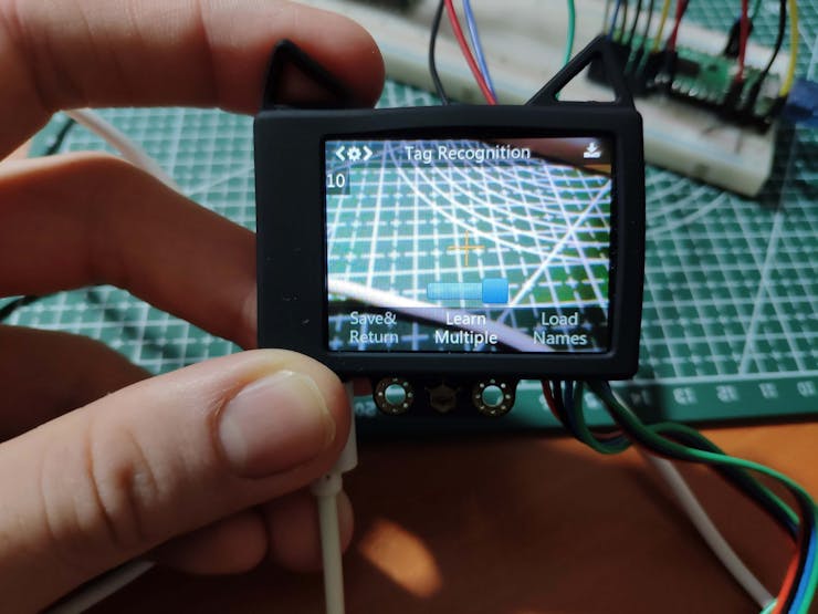 #️⃣ Finally, save the settings and return to the Tag Recognition mode.
 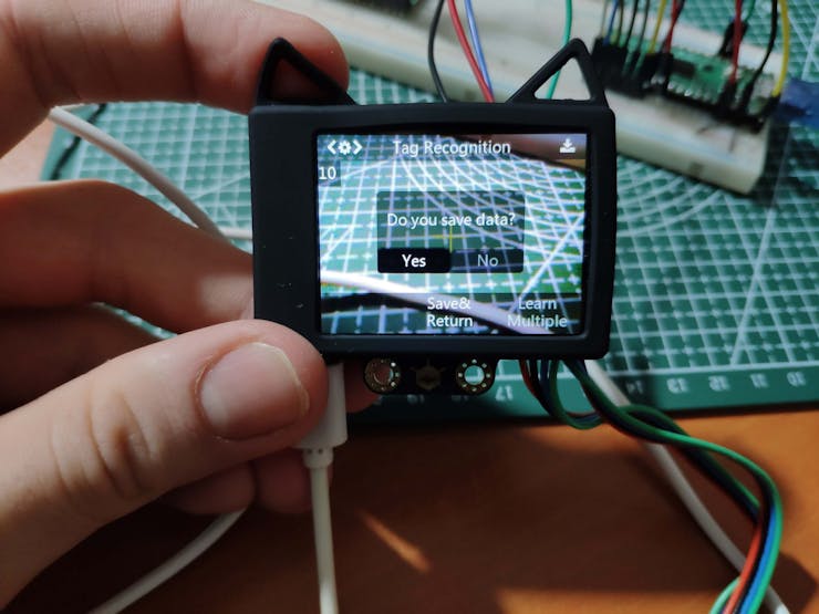 #️⃣ To learn a new tag (AprilTag), point the yellow + symbol to the selected tag and press the learning button. Then, release the learning button to complete learning the given tag.
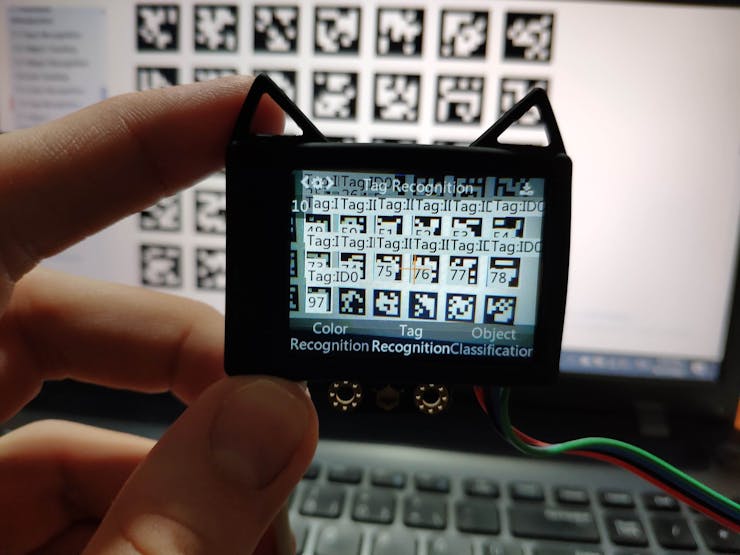
 #️⃣ To continue learning tags, short press the learning button before the countdown ends.
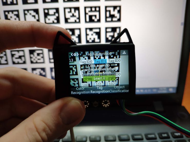
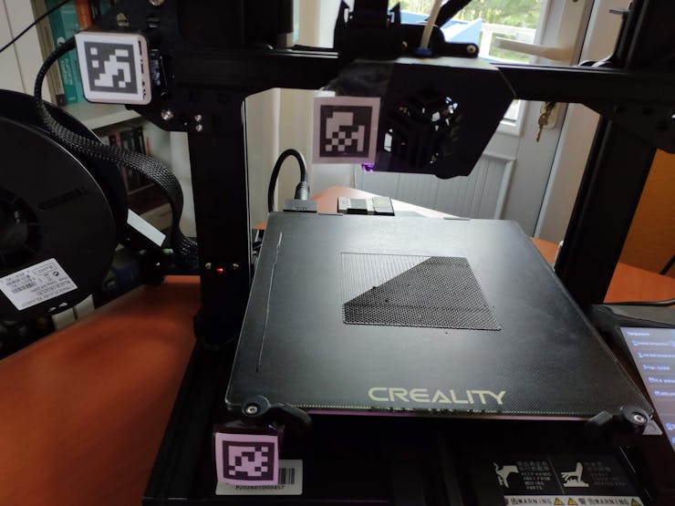
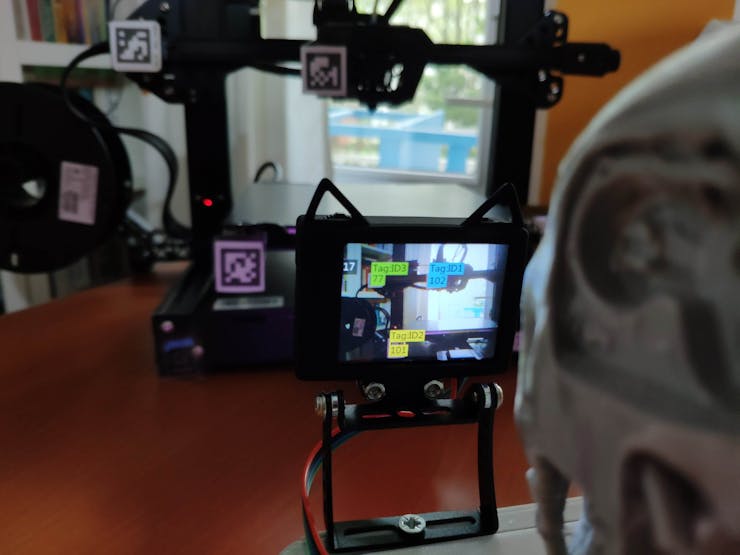
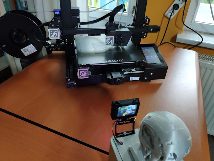
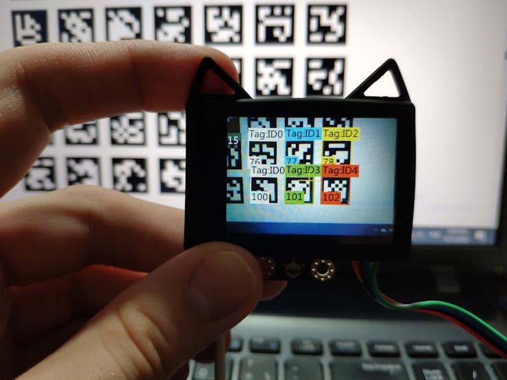 After training HuskyLens to learn tags (AprilTags) for each printer axis, I fastened each learned tag to my Creality CR-6 SE 3D printer's X-axis, Y-axis, and Z-axis without blocking its fans, sensors, or belts.
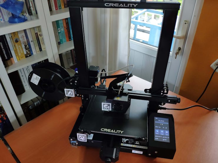
Step 6: Setting up Raspberry Pi Pico
Since I decided to program the Raspberry Pi Pico on Thonny, I needed to configure some settings and install MicroPython for Raspberry Pi Pico on Thonny.
#️⃣ First of all, download the latest Thonny IDE version, compatible with Windows, macOS, and Linux. If you are programming the Pico on Raspberry Pi, Thonny is already installed on the Raspberry Pi OS.
#️⃣ Then, find the BOOTSEL button on your Raspberry Pi Pico.
#️⃣ Press the BOOTSEL button and hold it while connecting the other end of the micro USB cable to your computer.
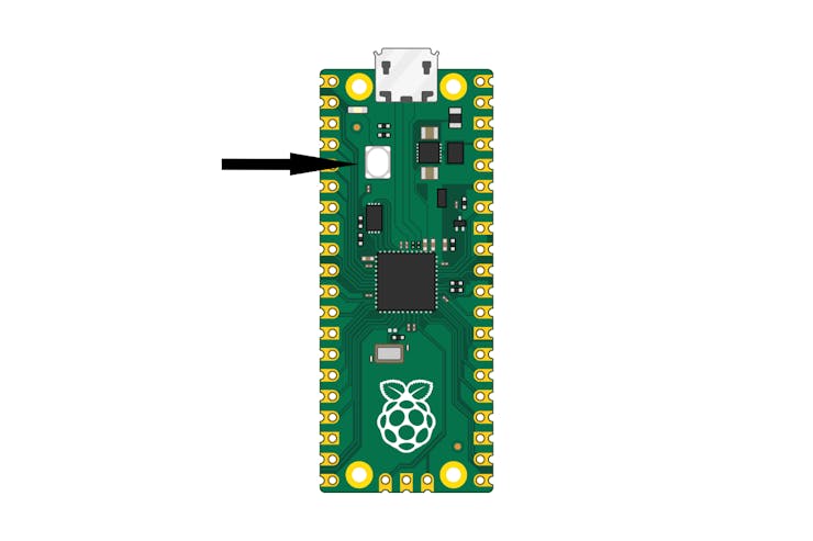
#️⃣ This puts the Raspberry Pi Pico into the USB mass storage device mode (Bootloader Mode).
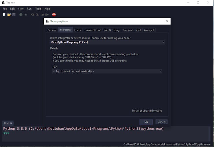
#️⃣ Thonny should automatically open the installation screen. If not, at the bottom right-hand corner of the window, click on the Python version, choose Configure interpreter..., and select MicroPython (Raspberry Pi Pico).
#️⃣ Then, on the Interpreter Tab screen, click the Install or update firmware link.
 #️⃣ When the dialog box pops up, click the Install button to copy the latest version of the MicroPython firmware to the Raspberry Pi Pico.
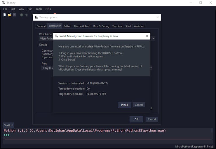
#️⃣ Wait for the installation to complete and click Close.
After completing the steps above, Thonny should recognize the board and firmware automatically when plugging the Raspberry Pi Pico to the computer without pressing the BOOTSEL button.
Step 6.1: Modifying CircuitPython libraries for Raspberry Pi Pico and the WIZnet Ethernet HAT
Since the WIZnet Ethernet HAT requires Adafruit CircuitPython libraries, I needed to set and configure CircuitPython on Thonny. Plausibly, Thonny has a built-in file transfer feature that makes copying files and libraries to the Raspberry Pi Pico very easy.
However, while working on this project, I encountered many bugs, errors, and incompatibilities regarding CircuitPython libraries. Therefore, I had to modify nearly all libraries and files to rectify the occurring issues and bugs.
Below, I will explain how to set CircuitPython and fix the mentioned issues and bugs step by step. But, you can download the lib.zip folder and copy the lib folder directly to your Raspberry Pi Pico without replicating the steps below.
#️⃣ First of all, download the latest versions of Blinka and PlatformDetect modules to run CircuitPython libraries on MicroPython.
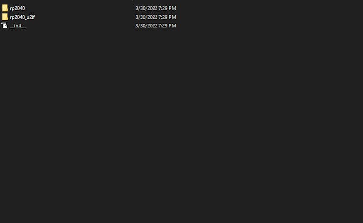
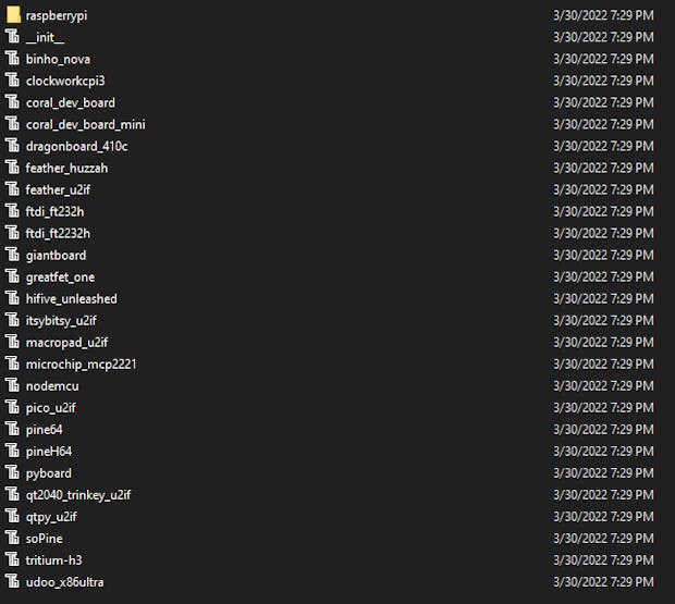
#️⃣ To install the PlatformDetect module to the Raspberry Pi Pico, copy the adafruit_platformdetect folder and upload it to the Pico under the lib folder.
#️⃣ To install the Blinka module to the Raspberry Pi Pico, copy everything inside the src folder and upload those files to the Pico under the lib folder.
#️⃣ To free up some space, remove the unnecessary files under the adafruit_blinka folder before uploading modules to the Pico.
#️⃣ To run the WIZnet Ethernet HAT, download the adafruit_bus_device and adafruit_wiznet5k libraries. Then, upload these libraries to the Pico under the lib folder.
#️⃣ If Thonny throws attribute errors like below, change the monotonic function with the ticks_cpu function in all files under the adafruit_wiznet5k folder.
Traceback (most recent call last):
  File "", line 49, in
  File "/lib/adafruit_wiznet5k/adafruit_wiznet5k.py", line 188, in __init__
AttributeError: 'module' object has no attribute 'monotonic'

Traceback (most recent call last):
  File "<stdin>", line 55, in <module>
  File "/lib/adafruit_wiznet5k/adafruit_wiznet5k.py", line 199, in __init__
  File "/lib/adafruit_wiznet5k/adafruit_wiznet5k.py", line 219, in set_dhcp
  File "/lib/adafruit_wiznet5k/adafruit_wiznet5k_dhcp.py", line 491, in request_dhcp_lease
  File "/lib/adafruit_wiznet5k/adafruit_wiznet5k_dhcp.py", line 363, in _dhcp_state_machine
AttributeError: 'module' object has no attribute 'monotonic'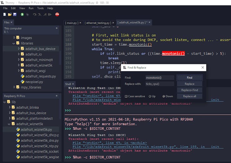
#️⃣ If Thonny throws an error regarding allocation, set the MAX_PACKET bytes to 3500 or lower in the adafruit_wiznet5k.py file under the adafruit_wiznet5k folder.
Traceback (most recent call last):
  File "<stdin>", line 50, in <module>
  File "/lib/adafruit_wiznet5k/adafruit_wiznet5k.py", line 176, in __init__
MemoryError: memory allocation failed, allocating 4000 bytes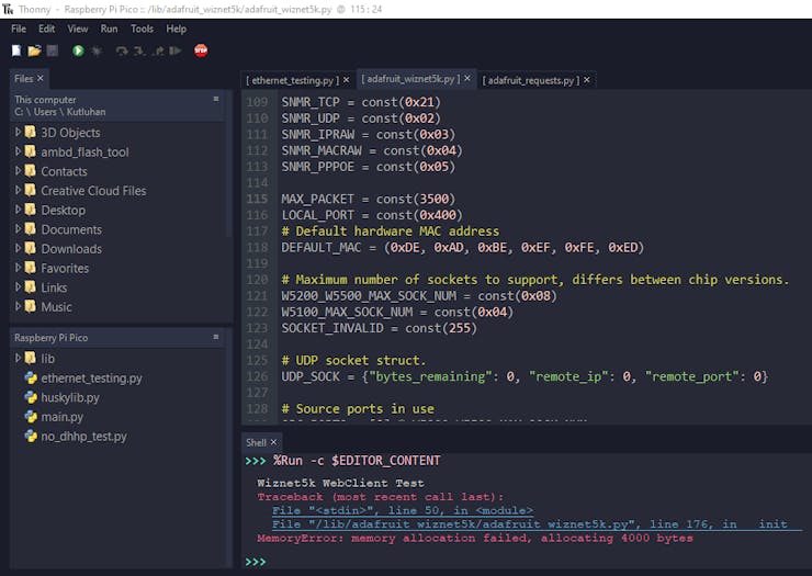
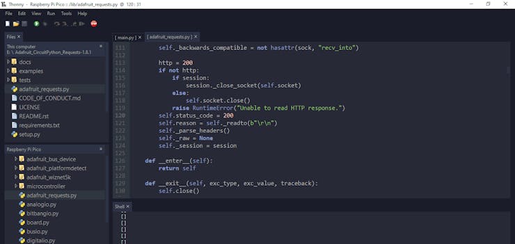
#️⃣ To make HTTP requests to a given web application with the WIZnet Ethernet HAT, download the adafruit_requests library. Then, upload the adafruit_requests.py file to the Pico under the lib folder.
Since the latest versions of the adafruit_requests library are not working with the adafruit_wiznet5k library, I utilized the 1.8.1 version in this project.
Also, I needed to modify the adafruit_requests.py file to disable checking for the server response since it causes timeout errors on Thonny.
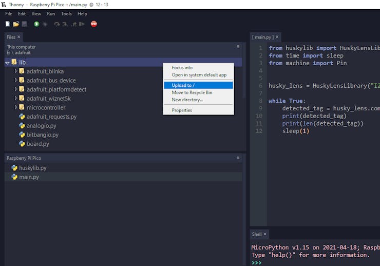
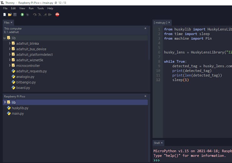
 After configuring module folders and modifying library files, I saved all required folders and files under the lib folder. Then, I uploaded the lib folder to the Raspberry Pi Pico via the built-in file transfer feature on Thonny.
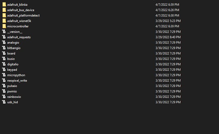
Step 6.2: Reading results generated by HuskyLens with Raspberry Pi Pico
Since HuskyLens does not provide an official library for the Raspberry Pi Pico, I modified these functions to obtain tag recognition results from HuskyLens via the I2C protocol.
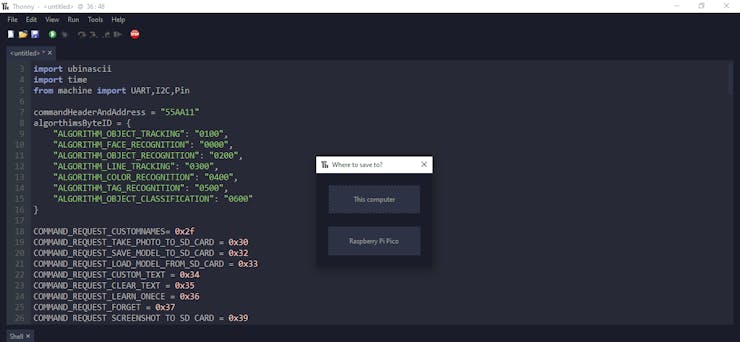
After modifying the functions, I uploaded them under the huskylib.py file to the Pico.
Then, I was able to get the learned blocks with IDs generated by HuskyLens for each detected tag (AprilTag) and process them to derive tag coordinates (tag positions).
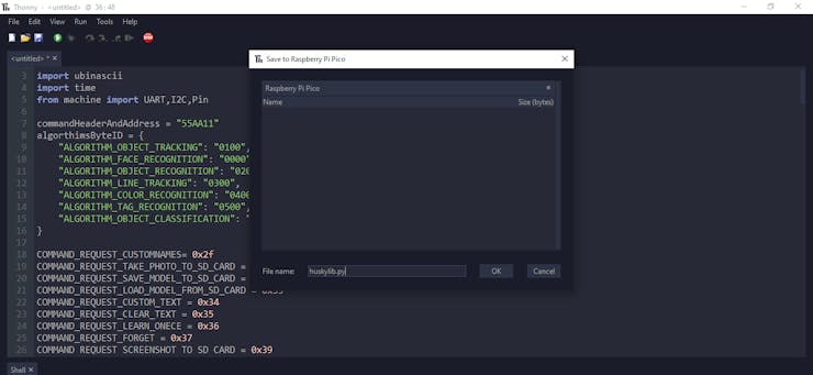
#️⃣ When saving code files to the Raspberry Pi Pico, click the Save button and choose the Raspberry Pi Pico option on Thonny.
Step 7: Programming Raspberry Pi Pico
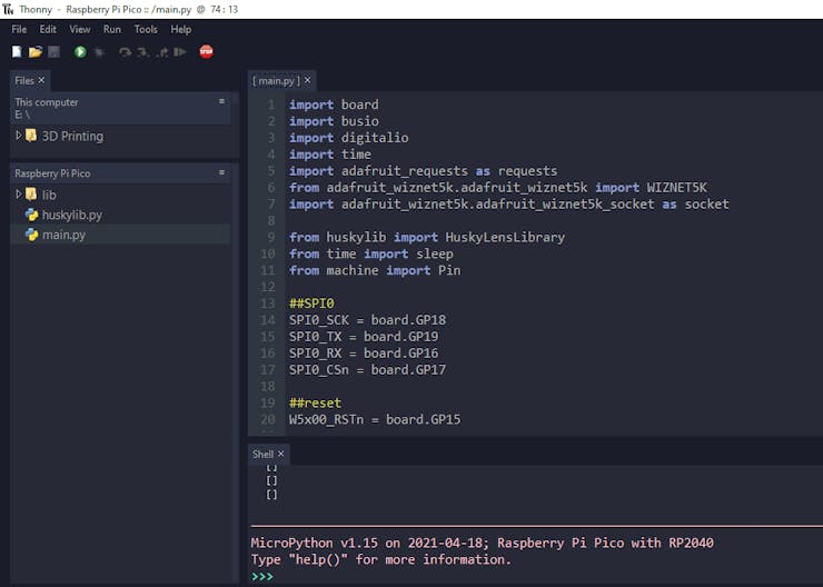
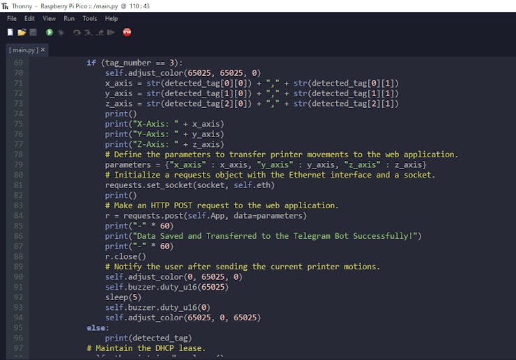
After uploading all required modules and libraries, I saved the following code in the main.py file to run it automatically when the Raspberry Pi Pico is powered up.
⭐ Include the required modules and libraries:
import board
import busio
import digitalio
import time
import adafruit_requests as requests
from adafruit_wiznet5k.adafruit_wiznet5k import WIZNET5K
import adafruit_wiznet5k.adafruit_wiznet5k_socket as socket
from huskylib import HuskyLensLibrary
from time import sleep
from machine import Pin, PWM
⭐ Define the IoT_3D_printer_tracker class and its functions.
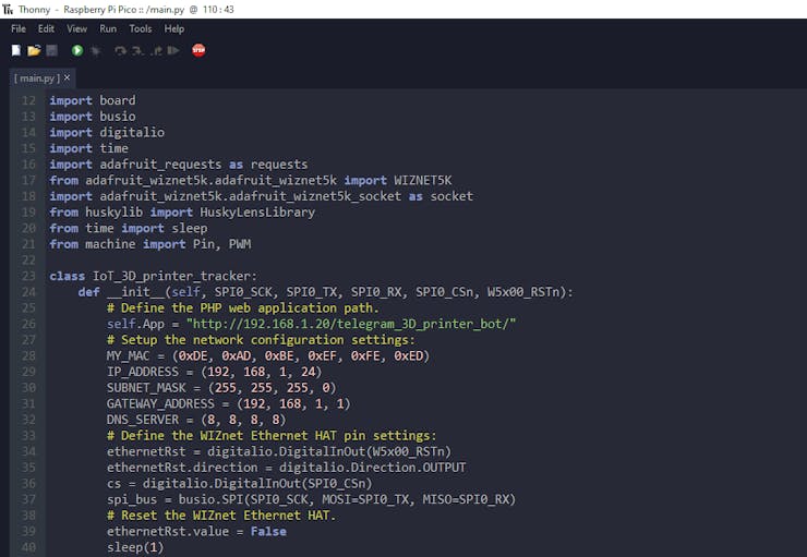
⭐ In the __init__ function:
⭐ Define the PHP web application path.
⭐ Setup the network configuration settings with the WIZnet Ethernet HAT's default MAC address:
0xDE, 0xAD, 0xBE, 0xEF, 0xFE, 0xED
⭐ Define the WIZnet Ethernet HAT pin settings.
⭐ Reset the WIZnet Ethernet HAT.
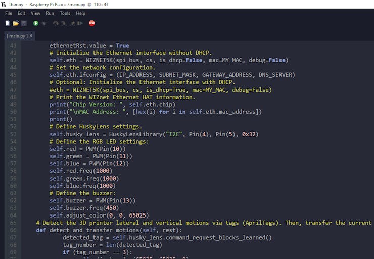
⭐ Initialize the Ethernet interface without DHCP.
⭐ Set the network configuration.
⭐ Print the WIZnet Ethernet HAT information.
⭐ Define the HuskyLens AI camera settings to activate the I2C protocol.
def __init__(self, SPI0_SCK, SPI0_TX, SPI0_RX, SPI0_CSn, W5x00_RSTn):
        # Define the PHP web application path.
        self.App = "http://192.168.1.20/telegram_3D_printer_bot/"
        # Setup the network configuration settings:
        MY_MAC = (0xDE, 0xAD, 0xBE, 0xEF, 0xFE, 0xED)
        IP_ADDRESS = (192, 168, 1, 24)
        SUBNET_MASK = (255, 255, 255, 0)
        GATEWAY_ADDRESS = (192, 168, 1, 1)
        DNS_SERVER = (8, 8, 8, 8)
        # Define the WIZnet Ethernet HAT pin settings:
        ethernetRst = digitalio.DigitalInOut(W5x00_RSTn)
        ethernetRst.direction = digitalio.Direction.OUTPUT
        cs = digitalio.DigitalInOut(SPI0_CSn)
        spi_bus = busio.SPI(SPI0_SCK, MOSI=SPI0_TX, MISO=SPI0_RX)
        # Reset the WIZnet Ethernet HAT.
        ethernetRst.value = False
        sleep(1)
        ethernetRst.value = True
        # Initialize the Ethernet interface without DHCP.
        self.eth = WIZNET5K(spi_bus, cs, is_dhcp=False, mac=MY_MAC, debug=False)
        # Set the network configuration.
        self.eth.ifconfig = (IP_ADDRESS, SUBNET_MASK, GATEWAY_ADDRESS, DNS_SERVER)
        # Optional: Initialize the Ethernet interface with DHCP.
        #eth = WIZNET5K(spi_bus, cs, is_dhcp=True, mac=MY_MAC, debug=False)
        # Print the WIZnet Ethernet HAT information.
        print("Chip Version: ", self.eth.chip)
        print("\nMAC Address: ", [hex(i) for i in self.eth.mac_address])
        print()
        # Define HuskyLens settings.
        self.husky_lens = HuskyLensLibrary("I2C", Pin(4), Pin(5), 0x32)
        # Define the RGB LED settings:
        self.red = PWM(Pin(10))
        self.green = PWM(Pin(11))
        self.blue = PWM(Pin(12))
        self.red.freq(1000)
        self.green.freq(1000)
        self.blue.freq(1000)
        # Define the buzzer:
        self.buzzer = PWM(Pin(13))
        self.buzzer.freq(450)
        self.adjust_color(0, 0, 65025)
⭐ In the detect_and_transfer_motions function:
⭐ If HuskyLens recognizes three tags (AprilTags) for each printer axis in the same frame, obtain tag coordinates (positions) for X-axis, Y-axis, and Z-axis.
⭐ Define the data parameters to transfer printer movements (detected tag positions) to the given web application.
⭐ Initialize a requests object with the Ethernet interface and a socket.
⭐ Then, make an HTTP POST request with the data parameters to the web application.
⭐ After sending the current printer motions successfully, notify the user via the RGB LED and the buzzer.
⭐ Maintain the DHCP lease.
def detect_and_transfer_motions(self, rest):
            detected_tag = self.husky_lens.command_request_blocks_learned()
            tag_number = len(detected_tag)
            if (tag_number == 3):
                self.adjust_color(65025, 65025, 0)
                x_axis = str(detected_tag[0][0]) + "," + str(detected_tag[0][1])
                y_axis = str(detected_tag[1][0]) + "," + str(detected_tag[1][1])
                z_axis = str(detected_tag[2][0]) + "," + str(detected_tag[2][1])
                print()
                print("X-Axis: " + x_axis)
                print("Y-Axis: " + y_axis)
                print("Z-Axis: " + z_axis)
                # Define the parameters to transfer printer movements to the web application.
                parameters = {"x_axis" : x_axis, "y_axis" : y_axis, "z_axis" : z_axis}
                # Initialize a requests object with the Ethernet interface and a socket.
                requests.set_socket(socket, self.eth)
                print()
                # Make an HTTP POST request to the web application.
                r = requests.post(self.App, data=parameters)
                print("-" * 60)
                print("Data Saved and Transferred to the Telegram Bot Successfully!")
                print("-" * 60)
                r.close()
                # Notify the user after sending the current printer motions.
                self.adjust_color(0, 65025, 0)
                self.buzzer.duty_u16(65025)
                sleep(5)
                self.buzzer.duty_u16(0)
                self.adjust_color(65025, 0, 65025)
            else:
                print(detected_tag)
            # Maintain the DHCP lease.
            self.eth.maintain_dhcp_lease()
            sleep(rest)
⭐ In the adjust_color function, change the RGB LED color by using the PWM frequency (0 - 65025).
def adjust_color(self, red_x, green_x, blue_x):
        self.red.duty_u16(65025-red_x)
        self.green.duty_u16(65025-green_x)
        self.blue.duty_u16(65025-blue_x)
⭐ Define the tracker class object with the WIZnet Ethernet HAT pins.
tracker = IoT_3D_printer_tracker(board.GP18, board.GP19, board.GP16, board.GP17, board.GP15)

while True:
    tracker.detect_and_transfer_motions(30)
Modes and Features
🌐🤖 If the WIZnet Ethernet HAT connects to the router via the Ethernet interface without DHCP, the device turns the RGB LED to blue.
 🌐🤖 If HuskyLens recognizes three tags (AprilTags) for each printer axis in the same frame, the device turns the RGB LED to yellow.
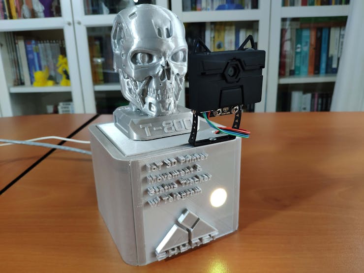
 🌐🤖 Then, if the WIZnet Ethernet HAT transfers tag coordinates (positions) for X-axis, Y-axis, and Z-axis to the PHP web application via an HTTP POST request successfully, the device turns the RGB LED to green and activates the buzzer to notify the user.
 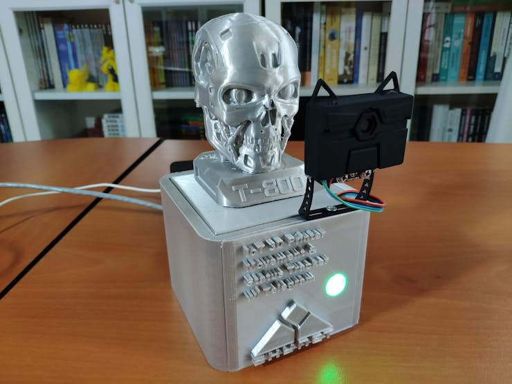 🌐🤖 After completing the first HTTP POST request successfully, the device turns the RGB LED to magenta as the default color.
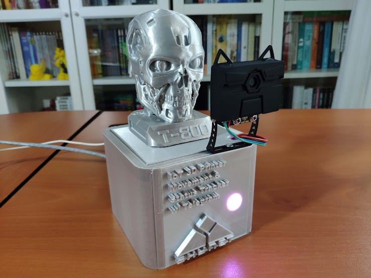
🌐🤖 When the web application receives the current printer movements (tag positions), it compares them to the previous printer movements stored in the database table to detect potential malfunctions related to the printer motions.
🌐🤖 Then, the application sends the current printer movements with a schematic describing 3D printer motions to the given Telegram bot via the Telegram Bot API.
🌐🤖 If the web application detects potential malfunctions on X-axis, Y-axis, or Z-axis, it adds notification messages to the transferred update up to two axes.
⚠️ X-Axis: Potential Malfunction Detected!
⚠️ Y-Axis: Potential Malfunction Detected!
⚠️ Z-Axis: Potential Malfunction Detected!

🌐🤖 If the web application detects malfunctions on three axes, it adds this notification message to the transferred update:
⛔ 3D Printer is not working!
 🌐🤖 Also, the device prints notifications and the detected printer movements (tag positions) on the shell for debugging.
 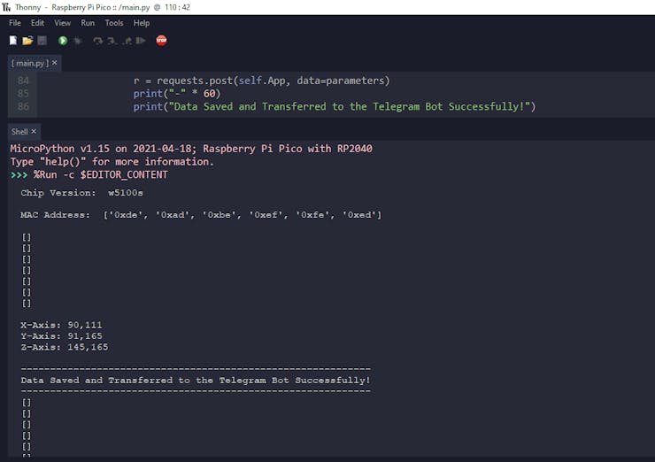 As far as my experiments go, the device works impeccably while tracking the printer movements and informing me of potential malfunctions related to the printer motions 🙂