
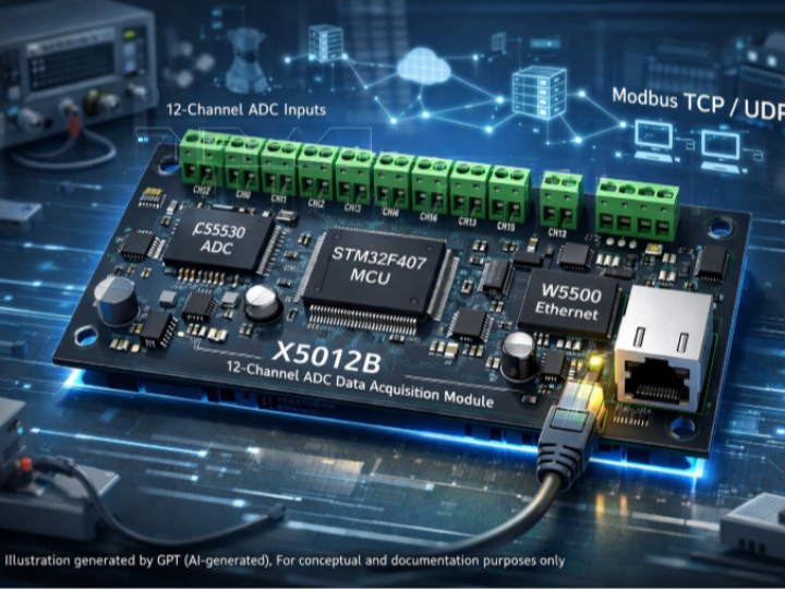
X5012B
Industrial 12ch DAQ firmware on STM32F407 with CS5530 ADCs. W5500 Ethernet outputs calibrated data via Modbus TCP and custom UDP. FreeRTOS separates sampling an
1. What This Project Actually Is
The X5012B firmware is a networked measurement controller designed for high-precision, multi-channel analog signal acquisition in industrial environments.
At the hardware level, the system combines:
- STM32F407VET6 MCU as the real-time control core
- 12-channel CS5530 ADCs for high-resolution sensor sampling
- WIZnet W5500 Ethernet controller for deterministic wired networking
At the firmware level, it integrates FreeRTOS, a Modbus TCP stack, and a custom UDP command protocol, turning the board into a standalone Ethernet-based data acquisition node rather than a simple MCU peripheral.
The project is not a demo or proof-of-concept. Its structure, calibration model, EEPROM persistence, and protocol separation indicate that it is intended for long-running, field-deployed measurement systems such as force sensors, load cells, or precision analog front-ends.
Why This Is Production-Ready, Not Just a Demo
This firmware represents a production-grade architecture that separates real-time data acquisition from unpredictable network operations—a fundamental requirement in industrial measurement systems.
Key Architectural Strengths:
Strict Task Isolation
- ADC sampling never blocks on network state
- Network failures don't affect measurement continuity
- Priority: Sensor reliability > Communication reliability
Unidirectional Data Flow
ADC Task ──▶ shared buffer ──▶ Network Task
- No reverse dependencies
- Network layer cannot control ADC state
- Structurally immune to deadlock
Minimal Critical Sections
The code uses extremely short lock periods (microseconds) with ISR-safe primitives:
LOCK_DATA(); memcpy(...); g_has_new_data = true; UNLOCK_DATA();
This is not common in hobbyist RTOS code and demonstrates real embedded systems experience.
Hardware Isolation via W5500
- TCP/IP processing offloaded to dedicated hardware
- MCU doesn't handle Ethernet interrupt storms
- Deterministic ADC timing guaranteed regardless of network load
These design choices aren't obvious from reading datasheets—they come from solving real production problems.
2. Firmware Architecture and FreeRTOS Task Model
2.1 System Startup Flow
File: Application/App_FreeRTOS.c
The firmware entry point App_freeRTOS_Start() performs a strictly ordered initialization sequence:
- BSP_Init() - Initializes clocks, GPIO, SPI, I2C, and board-level peripherals.
- Int_EEPROM_Init() - Prepares EEPROM access for persistent configuration and calibration data.
- Calib_Init() - Restores internal and user-defined calibration tables, with CRC validation.
- xTaskCreate(...) - Creates dedicated FreeRTOS tasks for networking, ADC processing, and LED status.
- vTaskStartScheduler() - Transfers control to the FreeRTOS kernel.
This structure ensures that all runtime logic executes inside deterministic RTOS tasks, not inside interrupt-heavy main loops.
2.2 Task Responsibilities
Defined in Application/App_FreeRTOS.c:
🔹 Task_Network_Core
- Initializes the W5500 Ethernet controller
- Applies network configuration (EEPROM or default)
- Starts Modbus TCP (port 502) via freeModbus
- Manages socket state machines
- Detects CFG button long-press for network reset
🔹 Task_ADC_Verify
- Samples all 12 ADC channels
- Applies scaling and calibration
- Updates shared buffers for Modbus/UDP access
🔹 Task_LED_Entry
- Visualizes system states (init error, communication active, network reset)
This clear task separation prevents network processing from blocking ADC sampling, which is critical for measurement integrity.
Production Design Pattern:
The task model implements a producer-consumer pattern with zero coupling:
- ADC task produces data at fixed intervals (never waits for network)
- Network task consumes data when sockets are ready (never blocks ADC)
- Shared buffer managed with minimal locking overhead
This architecture allows the system to maintain measurement accuracy even during network congestion, cable disconnection, or Modbus query storms.
3. ADC Sampling and Calibration Pipeline
3.1 ADC Driver Layer
Files: Driver/Dri_CS5530.c, BSP/src/bsp_cs553x.c, BSP/inc/bsp_cs553x.h
The ADC subsystem uses explicit chip-select mapping to support multiple CS5530 devices:
static const CS_Pin_Map_t ADC_CS_PINS[CS5530_COUNT] = { ... };
Sampling is abstracted through:
bool ADC_Sample(ADC_DevEnum dev, int32_t *code);
This design allows ADC hardware changes without touching higher-level application logic.
3.2 Calibration Strategy (Key Engineering Value)
Files: Application/App_Calib.c, Application/App_Calib.h
The firmware implements a two-layer calibration model:
Internal Calibration
- Fixed 3-point reference: 0 mV / 0.5 mV / 2 mV
- Restored at boot
- Guarantees baseline linearity
User Calibration
- Up to 10 calibration points per channel
- Stored in EEPROM
- CRC-protected
Processing flow: raw ADC → bit-shift → scaling → internal correction → user correction
This is characteristic of industrial measurement firmware, not hobby ADC examples.
Why This Matters for Production:
The dual-calibration model allows:
- Factory calibration to compensate for hardware variance
- Field calibration for specific sensor types without firmware changes
- Remote recalibration via Modbus without device access
This is how you build systems that can be manufactured at scale and maintained remotely.
4. Ethernet Networking with W5500
4.1 W5500 Initialization and Network Handling
Files: Interface/ETH/Int_eth.c, Common/net_config.c
The firmware uses WIZnet W5500 hardware TCP/IP offloading, initialized via:
Int_ETH_Init(); Int_ETH_ApplyNetInfo();
Key characteristics:
- Static IP or EEPROM-based configuration
- Socket reinitialization on network changes
- No software TCP/IP stack (no LwIP)
This significantly reduces MCU load compared to software-based Ethernet stacks.
Production Advantage:
W5500 handles all Ethernet interrupt processing in hardware. This means:
- ADC timing is never affected by network traffic bursts
- No Ethernet ISR competing with ADC sampling
- Predictable worst-case MCU load regardless of network activity
In measurement systems where timing jitter can corrupt sensor data, this hardware isolation is essential.
4.2 Modbus TCP Integration
Files: Interface/freeModbus/, Application/modbus_app.c
The project exposes measurement and configuration data via standard Modbus TCP, making it directly compatible with PLCs, SCADA systems, and industrial HMIs.
Register Design Highlights
Input Registers (04)
- Channel values (32-bit split into 2 registers)
- Relative and absolute measurements
Holding Registers (03/06/16)
- Network configuration
- Calibration tables
- Streaming control
Callbacks:
eMBErrorCode eMBRegInputCB(...) eMBErrorCode eMBRegHoldingCB(...)
This design allows full remote configuration without reflashing firmware.
Production-Ready Protocol Design:
The Modbus register map is designed for field serviceability:
- Zero-downtime configuration updates
- Persistent settings survive power loss
- CRC validation prevents corruption from interrupted writes
- Compatible with standard industrial automation tools
This is the difference between a prototype and a deployable product.
4.3 Custom UDP Protocol
Files: Application/App_Commu.c
In parallel with Modbus, the firmware implements a custom UDP protocol (port 9999) for:
- Device discovery
- Version queries
- EEPROM read/write
- Start/Stop streaming
- Tare operations
Packets are CRC16-protected, enabling lightweight but robust communication for custom tools or factory test software.
Why Both Modbus and UDP?
- Modbus TCP: Standard industrial integration (PLC/SCADA)
- UDP protocol: Factory testing, diagnostics, custom applications
Supporting both protocols simultaneously demonstrates proper socket resource management—a non-trivial task that many embedded Ethernet implementations get wrong.
5. System Status and Reliability Features
LED State Machine
File: Application/app_led.c
Defined system states include:
- Initialization error
- Running without communication
- Communication established
- Network reset
EEPROM + CRC Protection
Files: Interface/Int_EEPROM.c, Application/App_Calib.c
All critical parameters (network, calibration) are:
- Persisted in EEPROM
- Validated via CRC
- Automatically restored to defaults on corruption
Production Reliability Pattern:
The firmware implements defense-in-depth for configuration integrity:
- Write verification after every EEPROM operation
- CRC validation on every boot
- Graceful degradation to safe defaults on corruption
- No undefined states, ever
This level of defensive programming is what separates hobby projects from systems that run unattended for years.
6. Why W5500 Makes Sense Here
This project is a textbook example of where WIZnet W5500 is technically justified:
- Hardware TCP/IP offload avoids CPU jitter during ADC sampling
- Deterministic Ethernet latency suits industrial measurement
- Multiple hardware sockets support Modbus + UDP concurrently
- Reduced firmware complexity vs. LwIP-based designs
In measurement systems, data integrity matters more than bandwidth, and W5500 aligns perfectly with that requirement.
Technical Comparison:
Software TCP/IP Stack (LwIP):
- Ethernet ISR competes with ADC timing
- TCP processing can take 10-100+ µs per packet
- Memory allocation unpredictable
- Complex to debug under load
Hardware TCP/IP (W5500):
- Ethernet processing invisible to MCU
- Worst-case MCU load = SPI read time
- No dynamic memory allocation
- Network problems don't affect measurement
For production data acquisition, W5500 eliminates an entire category of timing-related bugs.
FAQ
Q1: Why use W5500 instead of a software TCP/IP stack like LwIP? Because ADC sampling and calibration require deterministic CPU behavior. Offloading TCP/IP to W5500 prevents network traffic from interfering with measurement timing.
Q2: Is this firmware suitable for industrial environments? Yes. The use of Modbus TCP, EEPROM persistence, CRC validation, and task separation strongly aligns with industrial controller design patterns.
Q3: Can calibration be updated remotely? Yes. Calibration points are exposed via Modbus holding registers and can be modified without reflashing firmware.
Q4: Why support both Modbus TCP and UDP? Modbus TCP ensures compatibility with industrial systems, while UDP provides a lightweight interface for diagnostics, factory tools, or custom software.
Q5: Is this tied to a specific sensor type? No. The CS5530 ADC and calibration pipeline allow the firmware to adapt to various analog sensors, including force and load measurement systems.
Q6: What makes this "production-ready" vs. a demo? The architecture prioritizes reliability over features: strict task isolation, unidirectional data flow, minimal locking, CRC-protected persistence, and hardware TCP/IP offload. These aren't obvious from datasheets—they're lessons learned from deploying measurement systems in the field.
Original Source
Repository: GZ2z2z / X5012B MCU: STM32F407VET6 Ethernet: WIZnet W5500 ADC: CS5530 Language: C Build: Keil uVision
Tags: #W5500 #STM32F4 #ModbusTCP #IndustrialIoT #DataAcquisition #ADC #FreeRTOS #WIZnet