


STM32H5-W6300 - Firmware OTA & WebServer
STM32H5-W6300 (Hygenis Board) Firmware OTA and Web Server Bootloader Project
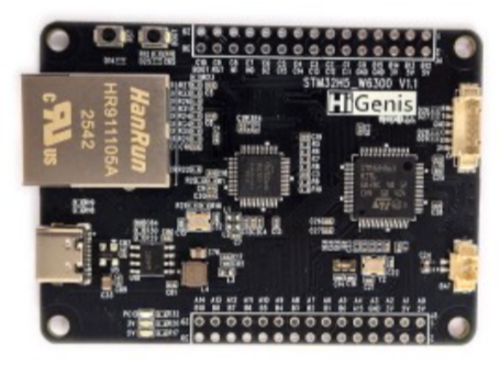
WIZnet - W6300
x 1

Well-known WIZnet maker Baram (chcbaram) built a firmware update system using STM32H5 and W6300 that goes beyond a simple OTA example.
The main idea is not just “download firmware over Ethernet.”
Instead, the user can update firmware through several different paths, including:
- UF2
- USB CDC
- WebHID
- TCP
- HTTP web interface
Internally, these methods share the same firmware update concept.
The new firmware is not written directly over the currently running application. It is first stored in a separate firmware slot. After reset, the bootloader applies the new image to the execution area.
If the new firmware repeatedly fails to boot or causes faults, the bootloader can automatically restore the previous working firmware.
Multiple Update Paths
        │
        ├─ USB UF2
        ├─ USB CDC
        ├─ WebHID
        ├─ W6300 TCP
        └─ W6300 HTTP
               │
               ▼
        Firmware Update Logic
               │
               ▼
          SLOT0 / SLOT1
               │
             Reset
               │
               ▼
           Bootloader
               │
          SLOT → FIRM
               │
               ▼
        Application Runs
               │
        ┌──────┴──────┐
      Success       Failure
        │              │
     Confirm        Rollback
In this architecture, the W6300 provides the Ethernet path for TCP- and HTTP-based firmware updates.
2. How Can the User Update the Firmware?
From the user's point of view, the same board can be updated in several different ways depending on the environment.
| Update Method | User Experience | Communication Path | Uses W6300 |
|---|---|---|---|
| UF2 | Copy a UF2 file to a USB drive | USB Mass Storage | No |
| USB CDC | Update from a PC tool or Python script | USB Serial | No |
| WebHID | Update directly from Chrome/Edge | Browser → WebHID → USB HID | No |
| TCP OTA | Send firmware to the board's IP address | Ethernet → TCP | Yes |
| HTTP Web OTA | Open the board's webpage and upload firmware | Ethernet → HTTP | Yes |
The W6300 is used only for the Ethernet-based update paths.
PC / Browser
     │
 Ethernet
     │
   W6300
     │
 TCP / HTTP
     │
 STM32H5
     │
Firmware Slot
The W6300 does not directly program the STM32H5 Flash.
It delivers the firmware data to the MCU. The STM32H5 firmware and bootloader handle:
- Flash erase
- Flash programming
- CRC verification
- Slot management
- Boot selection
- Rollback
3. How Is the Flash Memory Divided?
The STM32H5 Flash is divided into an execution area and firmware storage areas.
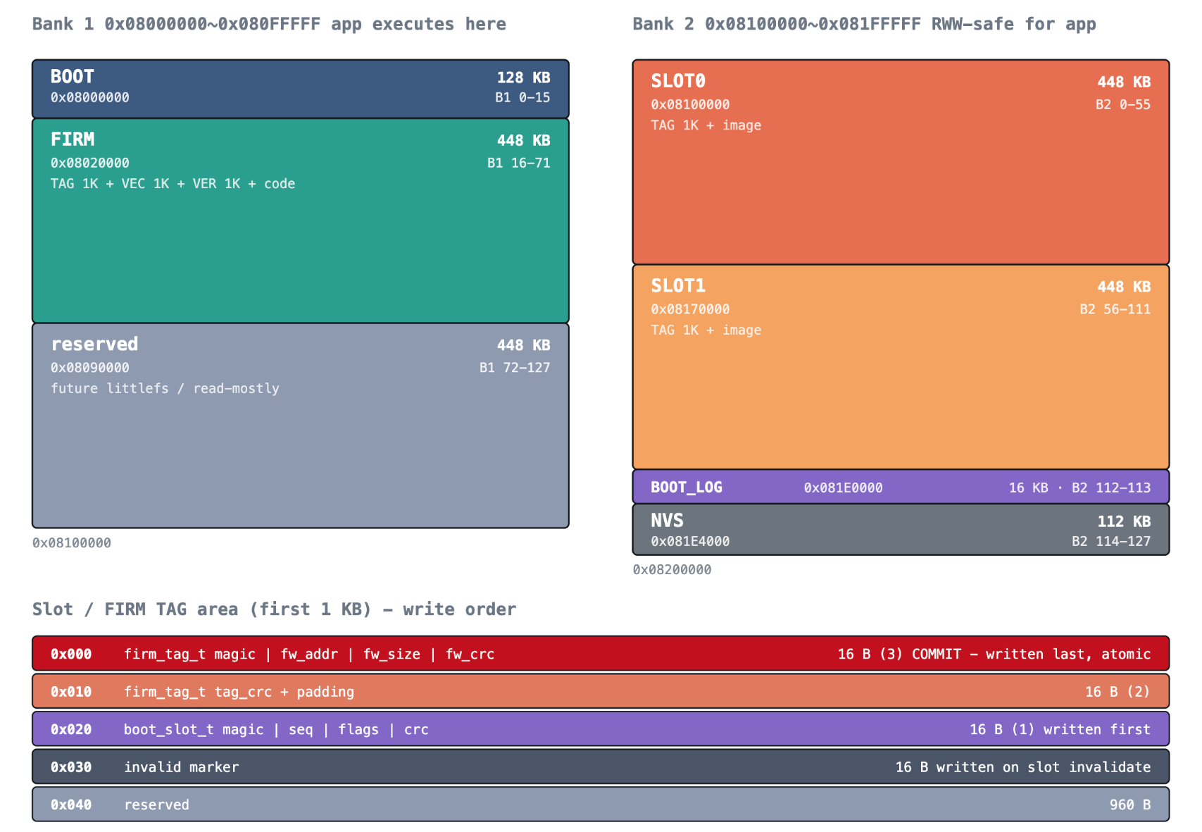
BOOT
The bootloader area.
It is responsible for applying new firmware, checking boot status, and performing rollback when necessary.
FIRM
The actual application execution area.
The STM32H5 always runs the main application from this fixed address.
SLOT0 / SLOT1
These are firmware image storage areas.
For example:
FIRM  = v1
SLOT0 = v1
SLOT1 = v2
In this state:
- FIRM is still running v1.
- SLOT0 keeps a known-good firmware image.
- SLOT1 contains the newly downloaded v2 candidate.
After reboot, the bootloader copies:
SLOT1 → FIRM
and then starts v2.
This Is Slightly Different from a Typical A/B OTA Design
A conventional A/B firmware architecture usually runs directly from either partition A or partition B.
Slot A → Execute
Slot B → Execute
This project instead uses:
SLOT0 ─┐
       ├─ Firmware storage
SLOT1 ─┘
       │
       ▼
      FIRM
       │
       ▼
    Execution
The application always runs from the same FIRM address.
One major advantage is that the application linker address remains fixed.
The firmware does not need to support execution from multiple Flash addresses.
4. How Does the System Decide Whether New Firmware Is Valid?
This is one of the most interesting parts of the project.
A simple OTA system may stop after checking CRC:
Download
   ↓
CRC OK
   ↓
Update Success
However, CRC only answers one question:
Was the firmware image transferred and stored correctly?
It does not tell us whether the firmware actually works.
For example:
CRC = PASS
Firmware boot = HardFault
is completely possible.
This project therefore performs two different levels of validation.
Stage 1: Firmware Image Validation
CRC is used to verify that the downloaded firmware image is intact.
This protects against corrupted transfers or Flash programming errors.
Stage 2: Runtime Boot Validation
The new firmware must also prove that it can actually boot and stay alive.
Conceptually:
New Firmware Applied
        │
        ▼
      Boot
        │
        ├─ Runs normally
        │       ↓
        │    Confirm
        │
        └─ Fault / Reset
                ↓
           boot_try++
                ↓
          Repeated failure
                ↓
             Rollback
The implementation also tracks fault-related resets separately.
For example:
fault_cnt >= 3
can indicate that the new firmware repeatedly enters a fault condition.
The key idea is:
Image integrity and runtime stability are treated as two different problems.
Failed Firmware Is Marked Invalid
Suppose:
SLOT0 = v1, working
SLOT1 = v2, failed
If v2 repeatedly fails to boot, the system records an invalid marker in that slot.
SLOT1
v2
INVALID
The bootloader then selects the previous valid firmware and restores it:
SLOT0(v1)
    ↓
   FIRM
The invalid marker is important because otherwise the bootloader could keep selecting the newer failed image again.
Without it:
v2 fails
   ↓
rollback to v1
   ↓
bootloader sees newer v2 again
   ↓
v2 applied again
   ↓
v2 fails again
The invalid marker essentially means:
“This firmware has already been tested and failed. Do not select it again.”
5. Why Can the Same CMD Interface Work with Multiple Transports?
This is one of the strongest software design points in the project.
The firmware update commands are separated from the underlying communication method.
The common command layer can handle operations such as:
- FW_BEGIN
- ERASE
- WRITE
- END
- VERIFY
- UPDATE
The transport underneath can change.
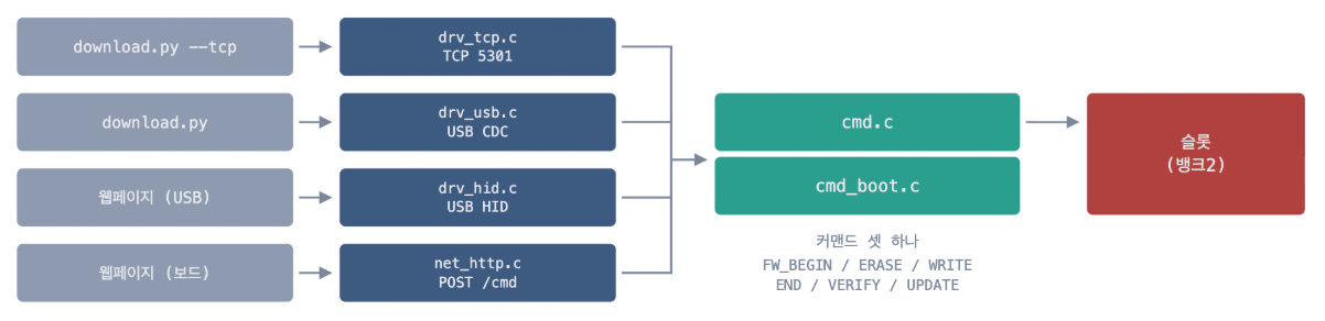
Each driver only needs to provide a common interface such as:
- open()
- close()
- available()
- flush()
- read()
- write()
From the point of view of cmd.c, it does not matter whether the bytes came from:
- USB CDC
- USB HID
- Ethernet TCP
The command parser receives the same type of byte stream.
This separation makes it much easier to add another transport later.
For example:
- UART
- CAN
- RS-485
- BLE
- MQTT
could potentially be added without rewriting the firmware update command logic.
For W6300, the TCP driver acts simply as another communication adapter between the command layer and the network socket.
6. Where Could This Bootloader Be Useful?
This architecture is especially useful for embedded systems that must operate reliably in the field for long periods.
Industrial Control Equipment
Consider many controllers installed on a factory network.
Management PC
     │
  Ethernet
     ▼
W6300 + STM32H5
The operator can update firmware remotely through TCP or HTTP.
If the new firmware repeatedly fails, the device can automatically restore the previous working version.
This reduces the risk of leaving equipment unusable after an update.
Building Automation and IoT Gateways
Devices installed in ceilings, electrical panels, or remote cabinets are often difficult to access physically.
Instead of opening the enclosure and connecting a debugger:
Browser
   ↓
Device IP
   ↓
Firmware Upload
can be enough.
The W6300 provides the wired Ethernet path for this update.
Production and Manufacturing
Different update methods can be used at different stages of the product lifecycle.
During manufacturing:
USB → Initial firmware programming
After deployment:
Ethernet → Remote firmware update
The same firmware update architecture can support both situations.
Development and Field Maintenance
Developers can choose the most convenient interface for the job.
Development       → USB CDC
Simple recovery   → UF2
Browser-based USB → WebHID
Installed device  → TCP / HTTP
Instead of maintaining completely different update mechanisms, the project reuses the same core update logic.
7. FAQ
Q1. Does the W6300 perform the firmware update itself?
No.
The W6300 provides the Ethernet communication path.
The STM32H5 handles Flash programming, slot management, boot validation, and rollback.
Q2. Why is it called WebHID if the board uses USB HID?
They refer to different layers.
USB HID is the device interface exposed by the STM32H5.
WebHID is the browser API that allows JavaScript in Chrome or Edge to communicate with that HID device.
Browser
   │
WebHID
   │
USB HID
   │
STM32H5
Q3. Why not write the new firmware directly into the FIRM area?
Because the current application is already running from the FIRM area.
Instead, the application first downloads the new image into a slot.
Application
   ↓
Write to SLOT
   ↓
Reset
   ↓
Bootloader
   ↓
SLOT → FIRM
This greatly reduces the risk of corrupting the currently running firmware during an interrupted update.
Q4. Can firmware pass CRC verification and still be rolled back?
Yes.
CRC only confirms that the firmware image is intact.
The firmware may still contain a software bug that causes:
- HardFault
- repeated reset
- failed initialization
- unstable startup
The system therefore also checks runtime boot behavior using mechanisms such as boot_try and fault_cnt.
Q5. Why are two firmware slots used?
A firmware update can technically be implemented with only one staging slot.
However, two slots allow the system to keep both:
Previous known-good firmware
+
New candidate firmware
at the same time.
If the candidate fails, the previous version can be restored immediately without downloading it again.