
roboracing-firmware
RoboRacing uses W5500 Ethernet on Arduino boards for TCP/UDP control across an autonomous racing car.
WIZnet - W5100
x 1

WIZnet - W5500
x 1
What the Project Does
RoboRacing Firmware is an embedded control project for an autonomous racing vehicle developed by the RoboJackets RoboRacing team. The repository describes the firmware as code that runs on the team’s microcontrollers and sensors, using Arduino and Mbed-based controllers that communicate with a ROS client over USB Serial or Ethernet TCP. The active platforms are Rigatoni and Sedani, while older Bigoli and Macaroni platforms are kept as archived references.
The main technical idea is a distributed vehicle control network. Instead of putting every actuator on one large controller, the vehicle separates functions across multiple boards: drive control, steering control, brake control, manual RC input, and emergency-stop logic. Each board owns a safety-critical function, and the boards exchange compact network messages over Ethernet.
For the Rigatoni platform, the provided project brief identifies five Arduino control boards using WIZnet W5500 Ethernet shields: E-Stop Motherboard, Drive Control, Steering Control, Manual RC Control, and Brake Control. The same brief lists static IP addresses from 192.168.0.3 to 192.168.0.7, with the ROS/NUC computer at 192.168.0.2.
This is a good WIZnet use case because autonomous racing control has different constraints from a normal web-connected Arduino project. The network must be simple, deterministic enough for repeated control messages, and easy to debug under field conditions. The project uses small ASCII command frames such as $v=2.5; for target velocity, $S=0.15; for steering, $B=123.4; for braking force, and $G; or $D; for E-Stop state propagation.
System Block Diagram
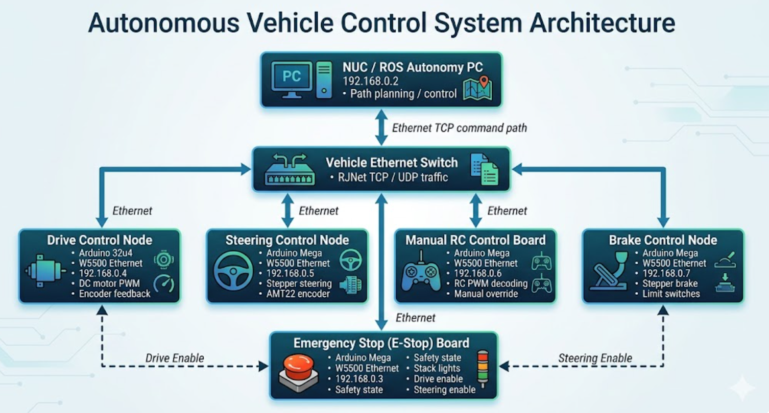
Generated By Gemini
Where WIZnet Fits
The WIZnet product in this project is the W5500 SPI hardwired TCP/IP Ethernet controller, used through Arduino Ethernet shields. The provided project brief states that all five Arduino control boards in the Rigatoni control system use W5500 Ethernet shields, with board-specific chip-select and reset pins.
W5500 sits at the transport boundary between each microcontroller and the vehicle Ethernet network. The Arduino boards run local control loops and safety logic, while W5500 provides the wired network interface used for TCP command exchange and UDP safety-state propagation.
That separation matters. An ATmega2560 or ATmega32u4 is small compared with a modern embedded Linux computer. It should spend its time reading encoders, checking limit switches, updating motor commands, and servicing watchdog timers. W5500 gives each board a practical Ethernet interface over SPI, allowing the control network to remain wired, inspectable, and compatible with the Arduino Ethernet library.
The project also shows a concrete W5500-specific engineering detail: ARP and TCP retry timing must be bounded. The uploaded brief points out that the firmware reduces WIZnet retransmission behavior to avoid long blocking delays when a destination MAC address cannot be resolved through ARP.
In a racing vehicle, that is not a minor optimization. If a network call blocks too long, a board may miss control-loop timing, fail to refresh the watchdog, or delay a transition into a safe state. The W5500 is useful here not just because it adds Ethernet, but because the Arduino Ethernet stack exposes retransmission controls that the team can tune for a real-time-ish control application.
Implementation Notes
Drive Control: Ethernet startup and bounded retries
File path: rigatoni/Drive/DriveControl/DriveControl.ino
The Drive board initializes Ethernet with a board-specific chip-select pin, assigns a static MAC/IP pair, checks that the Ethernet shield exists, waits for link, and then reduces retransmission behavior before starting its TCP server. The repository source shows this active initialization sequence in the Drive controller.
resetEthernet();
Ethernet.init(ETH_CS_PIN);
Ethernet.begin(driveMAC, driveIP);

while(Ethernet.hardwareStatus() == EthernetNoHardware) {
  Serial.println("Ethernet shield was not found. Sorry, can't run without hardware.");
  delay(100);
}

while(Ethernet.linkStatus() == LinkOFF) {
  Serial.println("Ethernet cable is not connected.");
  delay(100);
}

Ethernet.setRetransmissionCount(ETH_NUM_SENDS);
Ethernet.setRetransmissionTimeout(ETH_RETRANSMISSION_DELAY_MS);
server.begin();
This code exists because Drive Control is both a control board and a network node. It receives speed commands from Manual or NUC, talks to the Brake and E-Stop boards as a TCP client, and exposes its own server for incoming messages. The W5500 link must be present before the control role can safely begin.
The most important detail is the retransmission configuration. Default network retries can be acceptable in a desktop application, but they are risky in a vehicle controller. By reducing retry count and timeout, the firmware prefers a fast failure over a long blocking wait.
Drive Control: network messages feed the state machine
The Drive controller processes messages from several peers. It reads a full RJNet message, checks the sender IP, and updates motor enable state, brake acknowledgement timing, manual speed command, or NUC speed command. The source shows this logic in handleSingleClientMessage().
String data = RJNet::readData(otherBoard);
IPAddress otherIP = otherBoard.remoteIP();

if (data.equals(speedRequestMsg)) {
  RJNet::sendData(otherBoard, "v=" + String(get_speed()) + ",I=" + String(motorCurrent));
} else if (otherIP == estopIP) {
  motorEnabled = parseEstopMessage(data);
  lastEstopReply = millis();
} else if (otherIP == brakeIP) {
  lastBrakeReply = millis();
} else if (otherIP == manualIP) {
  manualTargetVelocity = parseSpeedMessage(data);
  lastManualSpeedTime = millis();
} else if (otherIP == nucIP) {
  nucTargetVelocity = parseSpeedMessage(data);
  lastNUCSpeedTime = millis();
}
This code explains why Ethernet is central to the system. The Drive board does not only run a motor; it continuously decides whether it is allowed to run the motor. If the E-Stop board stops replying, the Brake board stops acknowledging, or no valid speed commander is active, the state machine falls back toward a disabled state. The vehicle control policy is therefore distributed across network messages and local fail-safe checks.
E-Stop Motherboard: WIZnet timing comment
File path: rigatoni/EstopMotherboard/EstopMotherboard.ino
In the fetched current file, the Ethernet initialization block inside the E-Stop sketch appears commented out, so it should not be described as active runtime code in that file. However, the source still contains the WIZnet-specific note explaining why retransmission timing was tuned: unresolved ARP can make the WIZnet retry and block for a long time.
// If you don't set retransmission to 0, the WIZNET will retry 8 times
// if it cannot resolve the MAC address of the destination using ARP
// and block for a long time.

Ethernet.setRetransmissionCount(0);
Ethernet.setRetransmissionTimeout(ETH_RETRANSMISSION_DELAY_MS);
This is a strong engineering clue. The team was not just “using Ethernet”; they encountered a specific embedded networking failure mode and adjusted W5500 retry timing to protect vehicle behavior.
Communication Model
The Rigatoni network uses a compact custom protocol called RJNet. The provided project brief describes a shared TCP port, a message format using $ as a start marker and ; as an end marker, a 128-byte maximum buffer, and a 10 Hz communication cadence.
The messages are short because they carry control intent rather than large data streams:
$v=2.5;      target velocity in m/s
$S=0.15;     target steering angle in radians
$B=123.4;    requested braking force in newtons
$A=0.12;     steering angle feedback
$F=50.0;     braking force feedback
$G;          E-Stop state: go
$D;          E-Stop state: disabled
This is exactly the type of traffic where W5500 makes sense. The payloads are small, the messages are frequent, and wired connectivity is more valuable than high bandwidth. A shared Ethernet switch also makes the topology easier to observe with standard tools during debugging.
Safety Design
The safety design is layered. The uploaded brief identifies watchdog timers on the Brake, Drive, Steering, and E-Stop boards, with 500 ms timeouts on several actuator boards and 1000 ms on the E-Stop board. It also describes fail-safe transitions when Ethernet connections are lost or when E-Stop messages are not received within the expected window.
The Drive code confirms this pattern. It marks the system unsafe when the Brake or E-Stop TCP connection is lost, when either board times out, or when neither Manual nor NUC has recently provided a valid speed command.
This is the right way to think about W5500 in a safety-relevant student vehicle. Ethernet is not assumed to be perfect. Instead, Ethernet messages are treated as timed evidence that a peer is alive and that a command is still fresh. When that evidence disappears, the state machine disables motion.
Practical Tips / Pitfalls
- Use static IP addresses for each controller. In a vehicle network, fixed addressing makes peer identity, debugging, and timeout logic much simpler than DHCP.
- Bound W5500 retransmission behavior. Long ARP or TCP retry blocking can interfere with control loops and watchdog servicing.
- Do not rely on TCP connection status alone. The Drive controller also tracks the time since the last valid reply from Brake and E-Stop, which is a better safety signal.
- Keep messages short and parseable. The
$...;framing is simple enough for 8-bit boards and makes serial-style debugging easier. - Separate safety traffic from high-level autonomy. The NUC can command target speed, but local boards still enforce E-Stop, brake acknowledgement, and timeout behavior.
- Check Ethernet shield CS and reset pins per board. The project uses different W5500 CS/RST assignments across E-Stop, Drive, Steering, Manual, and Brake boards.
- Treat link loss as a normal event. A racing vehicle should enter a safe state when a cable, switch port, or peer board fails.
FAQ
Q: Why use W5500 for RoboRacing Firmware?
A: W5500 gives each Arduino controller a wired Ethernet interface through the standard Arduino Ethernet library. That is useful for a distributed vehicle where Drive, Brake, Steering, Manual, and E-Stop boards must exchange small control messages at a predictable cadence without depending on Wi-Fi.
Q: How does W5500 connect to the Arduino boards?
A: The W5500 Ethernet shields connect over SPI, with a board-specific chip-select pin and reset pin. The uploaded project brief lists W5500 CS/RST assignments for E-Stop, Drive, Steering, Manual, and Brake boards.
Q: What role does W5500 play in this project?
A: W5500 is the wired network interface for the vehicle’s distributed control system. It carries TCP command messages between boards and supports UDP-style E-Stop state broadcasting in the documented architecture. It does not run the control algorithms; it transports the commands and status signals that those algorithms depend on.
Q: Can beginners follow this project?
A: The basic Ethernet initialization is approachable for Arduino users, but the full system is not beginner-level. It combines W5500 networking, watchdog timers, actuator control, encoder feedback, RC override, static IP planning, and safety state machines.
Q: How does W5500 compare with Wi-Fi here?
A: Wi-Fi is convenient for telemetry, but it is a poor fit for low-level vehicle control because RF conditions and association state can change unpredictably. W5500 Ethernet gives the team a wired topology with fixed nodes, visible link state, and easier failure handling.
Source
- Original project: RoboJackets/roboracing-firmware.
- Repository license: Apache-2.0.
- Verified source files:
rigatoni/Drive/DriveControl/DriveControl.inoandrigatoni/EstopMotherboard/EstopMotherboard.ino. - Provided project brief: RoboRacing Firmware technical description for WIZnet curation.
Tags
#W5500 #WIZnet #ArduinoEthernet #RoboRacing #AutonomousVehicle #DistributedControl #Ethernet #TCP #UDP #RJNet #ArduinoMega #ATmega32u4