
MySmartHouse3
An ESP32-C6 gateway uses the W5500 to bridge a CAN-based smart home network to an MQTT cloud.

WIZnet - W5500
x 1
What the Project Does
This project is a gateway firmware design for a multi-node smart home system built around two very different network layers.
At the field level, sensors, relays, and motor-control nodes communicate over a CAN 2.0 bus. That local bus is used for deterministic, wired device-to-device communication across rooms or floors. Each slave node handles a concrete function such as relay output, sensor reporting, or motor actuation. The gateway node is device #1, and it acts as the master of the CAN segment.
At the uplink level, the master node bridges that CAN traffic to an MQTT broker over secure Ethernet. The project description shows the cloud path as MQTT over WebSocket Secure, with TLS on top, and the gateway uses ESP-IDF components to bring up Ethernet, obtain an IP address, and run the MQTT client stack.
The core system flow is straightforward.
A local event begins on a slave node. For example, a temperature sensor, relay state change, or motor control event is encoded into a CAN frame and transmitted onto the bus. The master receives that frame, parses it, optionally logs it to NVS, checks whether scenario logic or parameter rules need to run, and then forwards relevant state upstream as MQTT data. In the opposite direction, cloud-originated commands arrive through MQTT, enter the gateway through Ethernet, are translated into CAN control messages, and are then dispatched to the target device node.
This is what makes the project more than a generic “ESP32 with Ethernet” example. Architecturally, it is a protocol bridge between a field bus and an IP network:
Cloud app or server → MQTT broker → Ethernet uplink → gateway firmware → CAN bus → target device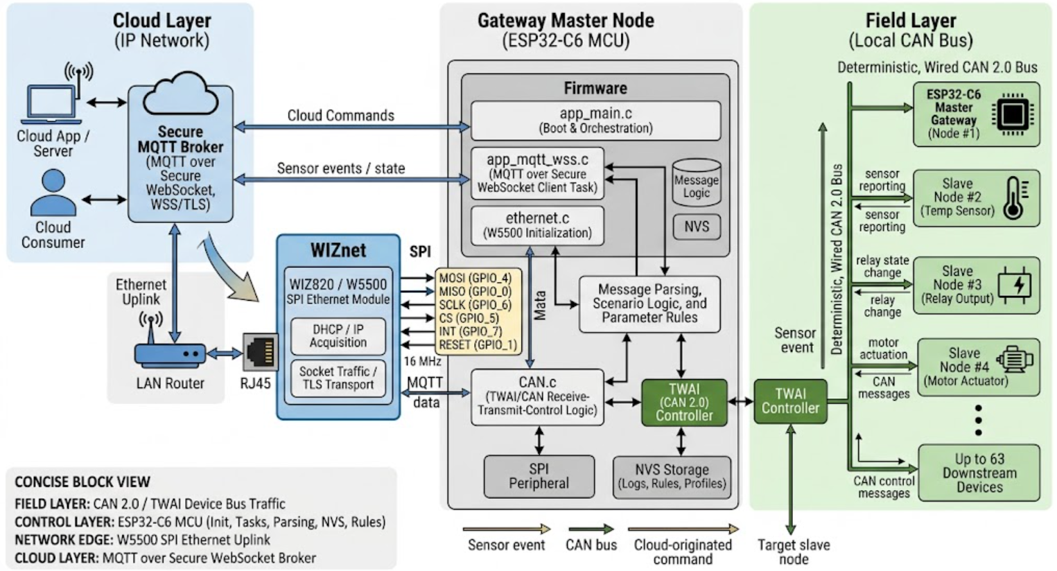
Generated By Gemini
and in reverse:
sensor or actuator event → CAN bus → gateway firmware → Ethernet uplink → MQTT broker → cloud consumer.
The provided markdown also makes clear that the firmware is organized around separate roles rather than a monolithic loop. app_main.c orchestrates boot and task startup, CAN.c handles TWAI/CAN receive-transmit-control logic, ethernet.c initializes the W5500-based Ethernet path, and app_mqtt_wss.c manages MQTT over secure WebSocket. That separation matters because it shows the gateway is intentionally structured as a transport bridge, not just as an application demo.
Where WIZnet Fits
The exact WIZnet product used here is the W5500, implemented through a WIZ820 SPI Ethernet module according to the provided project description. In this system, the W5500 sits between the ESP32-C6 MCU and the external LAN. It is connected over SPI on the MCU side and out to RJ45 and the router on the network side.
Functionally, the W5500 is the gateway’s Ethernet front end. Its position in the architecture is very specific:
ESP32-C6 application logic and bus control
→ SPI
→ W5500 Ethernet controller
→ RJ45 / LAN router
→ Internet / MQTT broker.
That placement gives the project a clear division of labor.
The CAN bus handles local device coordination. The ESP32-C6 handles gateway logic, task scheduling, profile storage, and message translation. The W5500 handles the wired Ethernet interface that makes cloud connectivity possible for the whole CAN domain. In practical terms, W5500 is the single network exit point for as many as 63 downstream devices behind the gateway.
This matters technically for three reasons.
First, the project avoids putting a separate TCP/IP-capable network interface on every device node. That keeps the leaf nodes simpler and preserves CAN as the local control backbone.
Second, the wired Ethernet link is stable and physically bounded in a way that suits a gateway role better than a wireless uplink in installations where reconnection behavior and interference can become operational problems.
Third, the project uses the W5500 at the point where network state becomes system-critical: DHCP, IP acquisition, socket traffic, and MQTT/TLS transport all depend on that Ethernet path being present and recoverable. The provided boot flow shows that the master node brings up W5500 Ethernet, binds it into the ESP-IDF network stack, waits for IP acquisition, and only then starts the MQTT WSS task. That confirms the W5500 is not optional in the architecture. It is a prerequisite for the cloud side of the system.
A concise block view looks like this:
- Field layer: CAN 2.0 / TWAI for device bus traffic
- Control layer: ESP32-C6 for initialization, task control, message parsing, NVS, and rule execution
- Network edge: W5500 for Ethernet uplink over SPI
- Cloud layer: MQTT over secure WebSocket to the broker.
Implementation Notes
I do not have the original repository source tree here, so I cannot independently verify exact line numbers from the repo itself. What I can verify is the structure and code excerpts included in the provided markdown, and those excerpts are enough to explain the system integration without inventing missing details.
The clearest integration evidence is the boot sequence described in the markdown. The master node’s startup flow explicitly lists:
eth_init()inethernet.cesp_netif + TCP/IP stackbinding- IP acquisition wait
mqtt_wss_client_task()inapp_mqtt_wss.c.
That ordering matters because it shows the actual dependency chain. CAN and local tasks can exist on their own, but cloud messaging is only launched after the W5500 Ethernet path is alive.
The provided configuration snippet also shows how the W5500 is enabled in software:
CONFIG_ETH_USE_SPI_ETHERNET=y
CONFIG_ETH_SPI_ETHERNET_W5500=y
This indicates the project is using the ESP-IDF SPI Ethernet path rather than a custom raw driver. In other words, W5500 is integrated through the standard ESP-IDF Ethernet abstraction, which is the right architectural choice for maintainability and compatibility with the rest of the network stack.
The markdown also includes the W5500 driver instantiation pattern:
eth_w5500_config_t w5500_config = ETH_W5500_DEFAULT_CONFIG(1, &spi_devcfg);
w5500_config.int_gpio_num = spi_eth_module_config->int_gpio;
esp_eth_mac_t *mac = esp_eth_mac_new_w5500(&w5500_config, &mac_config);
esp_eth_phy_t *phy = esp_eth_phy_new_w5500(&phy_config);
esp_eth_driver_install(ð_config_spi, ð_handle);From a system-design perspective, this is the key integration point. It shows that the W5500 is brought in as the Ethernet MAC/PHY side of the gateway uplink, not as an ad hoc socket driver bolted directly into application code. That is why the rest of the firmware can treat Ethernet, IP, TLS, and MQTT as part of a clean layered stack.
The hardware mapping in the provided markdown is also useful because it shows the W5500 is connected in a practical interrupt-driven SPI design:
MOSI: GPIO_4
MISO: GPIO_0
SCLK: GPIO_6
CS: GPIO_5
INT: GPIO_7
RESET: GPIO_1
SPI clock: 16 MHz.
That layout explains why the W5500 is appropriate here. The gateway needs a compact, SPI-connected Ethernet path that can coexist with an MCU already busy with CAN receive/transmit tasks and NVS-backed profile handling. The W5500 occupies exactly that boundary between local real-time control and external IP connectivity.
Practical Tips / Pitfalls
- Confirm that the gateway role is isolated to the master node. In this project, cloud connectivity belongs to device #1, so avoid spreading Ethernet responsibilities into CAN slave firmware without a clear reason.
- Keep the W5500 interrupt line wired and handled correctly. An interrupt-driven receive path is preferable to polling in a gateway that is already servicing CAN tasks.
- Budget startup time around Ethernet readiness. The provided flow waits for IP acquisition before starting MQTT, which is the correct dependency order for stable bring-up.
- Validate SPI signal integrity early, especially at the configured 16 MHz clock. Gateway failures that look like “cloud instability” often begin as board-level SPI issues.
- Treat CAN and MQTT as separate timing domains. CAN may produce bursts that do not map neatly to cloud publish cadence, so queueing and back-pressure handling need attention.
- Use NVS carefully for device profiles and cached network state. This project stores many downstream profiles, so partition layout and write frequency matter.
- Test reconnect behavior under cable unplug, router reboot, and broker timeout conditions. In a gateway design, Ethernet recovery is just as important as first boot success.
FAQ
Q: Why use W5500 in this project instead of adding network connectivity to every smart home node?
A: The architecture is built around a CAN field bus with one master gateway. W5500 is therefore used once, at the boundary between the local CAN domain and the IP network, so a single Ethernet interface can expose the entire multi-node installation to MQTT without redesigning every slave as an IP endpoint.
Q: How does W5500 connect to the ESP32-C6 in this system?
A: It connects over SPI, with dedicated MOSI, MISO, SCLK, chip-select, interrupt, and reset lines. The provided pin map shows a conventional SPI Ethernet integration, which is appropriate for a gateway MCU that must also manage CAN tasks and storage.
Q: What role does the W5500 play in this specific project?
A: It is the Ethernet uplink interface for the gateway node. It carries MQTT-over-secure-WebSocket traffic between the ESP32-C6 firmware and the LAN router, allowing CAN events to be published to the cloud and cloud commands to be translated back into CAN messages.
Q: Can a beginner follow this project?
A: It is not a beginner-only project. A reader should already be comfortable with ESP-IDF, SPI peripheral bring-up, CAN/TWAI concepts, and MQTT/TLS deployment, because the project is really a multi-layer gateway rather than a simple sensor example.
Q: How does this compare with a Wi-Fi uplink for the same gateway role?
A: A Wi-Fi uplink can reduce cabling, but this design is clearly optimized around a wired-control mindset: CAN for local field communication and Ethernet for the cloud edge. In that context, W5500 fits the system goal better because it keeps the gateway’s uplink on a stable wired path rather than introducing an additional wireless dependency at the point where all field traffic exits to the cloud.
Tags
#W5500 #ESP32C6 #CAN #TWAI #MQTT #Ethernet #SmartHome #IoTGateway #WIZnet