
Industrial RGB LED Control: Low-Cost Modbus HMI System with W5500
A low-cost Modbus-based WS2812 control system combining C# HMI, STM32 firmware, and WIZ750SR TCP/IP—an affordable alternative to industrial LED controllers.
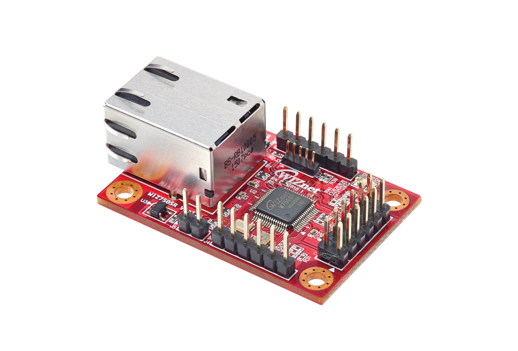
WIZnet - WIZ750SR
x 1
Why This Project Matters
This isn't a typical LED blinker project. It's a fully-functional industrial HMI system with complete Modbus protocol implementation, a professional GUI, STM32 firmware, and TCP/IP network expansion.
It was created by SeongmiAppa (성미아빠), a well-known maker and community contributor in Korea’s electronics scene—actively involved in the “Electronics Craft Knowledge-Sharing Community (전자공작 지식나눔 전문 카페)” and “Danggeuni’s AVR Playground (당근이의 AVR 갖구 놀기)” on Naver. His projects are widely recognized for their depth, polish, and practical engineering value, and this system is one of his standout works.
Commercial Solution: $2,000 - $20,000+
- Industrial Modbus LED Controller: $200 - $700
- HMI Touch Panel: $800 - $2,000
- Modbus Gateway: $100 - $300
This DIY Solution: $100 - $200
- STM32 Board + WS2812 LEDs + WIZ750SR + PC Software = 90-95% cost savings
System Architecture Overview

PC HMI (C#) → Modbus TCP/Serial → WIZ750SR → UART → STM32 Slave → WS2812 LEDs (8 units)The system operates in layers:
- User Interface: C# WinForm HMI
- Network Layer: WIZ750SR (TCP ↔ UART gateway)
- Control Logic: STM32 Modbus Slave
- Hardware: 8× WS2812 RGB LEDs
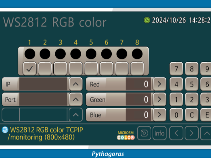
Part 1: LCD Visualization (HMI Panel Design)
Role: Professional GUI designed to replicate industrial HMI touch panels.

GUI Components:
- 8 LED Status Indicators: Real-time color display with checkboxes
- RGB Value Display: Three digital displays showing current R/G/B values (0-255)
- Numeric Ten-Key Pad: For RGB value input with 0-9, C (clear), E (enter)
- IP/Port Configuration: Displays connection settings (192.168.0.13:5000)
- Control Buttons: Up/Down arrows, Enter, navigation buttons
- Connection Status: LED indicator showing TCP connection state
- Timestamp Display: Real-time system clock
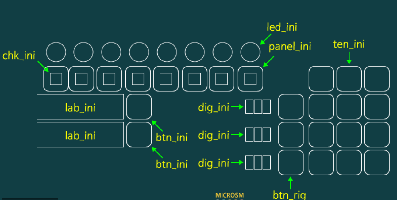
UI Layout:
- Left panel: LED selection (1-8) with visual feedback
- Center: RGB value inputs with increment/decrement controls
- Right: Numeric keypad for direct input
- Bottom: Connection info and status display
Significance: Completely replaces expensive industrial touch panel HMIs ($800-$2,000) with a free PC-based WinForm application that looks and functions identically to commercial HMI panels.
→ Professional industrial UI/UX at zero cost
Part 2: C# PC HMI (Modbus RTU via Serial)
Role: Acts as the Modbus RTU Master, generating and sending commands from a PC to the STM32 controller through RS232 serial communication.
Modbus Packet Builder
Generates proper Modbus RTU frames (Function 0x03 Read, 0x06 Write) including CRC16.
Real-Time LED Control
Controls 8 WS2812 LEDs × RGB = 24 registers (0–255 range).
Serial TX/RX Engine
Periodic transmit timer (timer1_sub)
Asynchronous receive handler (serialPort_DataReceived)
Full CRC check and packet validation
GUI Synchronization
Updates LED color previews using received register values.
Diagnostic Logging
Displays TX/RX data in HEX for debugging and verification.
Communication Path
PC (C# HMI) → RS232 Serial → STM32 Modbus Slave → WS2812 RGB LEDs
Why It Matters
This module provides a complete industrial-grade Modbus RTU Master implementation—not a simple LED demo, but a fully structured communication engine usable in actual HMI and automation systems.
→ WS2812
→ Industrial-grade Modbus Master implementation
Part 3: STM32 Modbus Slave Firmware
Role: Interprets Modbus Master commands and controls WS2812 LEDs accordingly.
Core Implementation:
- USART Interrupt Handler: Receives Modbus frames byte-by-byte
- Frame Parser: Validates packet structure and CRC
- Function Code Processing:
- 0x03: Read Holding Registers (returns current RGB values)
- 0x06: Write Single Register (updates LED color)
- Register Map Management: Maps addresses 0-23 to LED channels
- WS2812 Driver: Generates precise timing signals for LED control
- Exception Handling: Returns proper Modbus error codes
Register Map Structure:
Address 0: LED1 Red (0-255)
Address 1: LED1 Green (0-255)
Address 2: LED1 Blue (0-255)
Address 3: LED2 Red (0-255)
...
Address 23: LED8 Blue (0-255)
Firmware Flow:
- Receive Modbus frame via UART interrupt
- Validate CRC16 checksum
- Parse function code and address
- Execute read/write operation on register map
- Update WS2812 LED output
- Send Modbus response with CRC
→ Commercial-grade Modbus Slave architecture
Part 4: TCP/IP Network Expansion (WIZ750SR Integration)
Role: Transforms the serial-based system into a network-enabled industrial device.

Key Innovation:
The WIZ750SR acts as a transparent TCP ↔ UART gateway, enabling network control without any STM32 firmware modifications.
System Expansion:
- Before: PC → Serial → STM32
- After: PC → TCP/IP → WIZ750SR → UART → STM32
- Result: Remote control from anywhere on the network
Multi-Device Support:
As shown in the diagram, the system can control multiple STM32 units simultaneously through a single network connection, making it scalable for larger installations.
→ From local device to networked industrial controller
Complete System Flow Sequence
[Insert Images 1 & 2]
         ┌─────────────────────────────────┐
         │       PC HMI (C# WinForm)       │
         │  - RGB value input (0~255)     │
         │  - LED 1~8 selection           │
         │  - Modbus packet generation    │
         └───────────────┬─────────────────┘
                   Modbus TCP/Serial
                          │
                          ▼
              ┌──────────────────────┐
              │     WIZ750SR         │
              │  TCP → UART Gateway  │
              └──────────┬───────────┘
                       UART
                         │
                         ▼
              ┌─────────────────────────────┐
              │   STM32 Modbus Slave        │
              │  - Packet parsing/CRC check │
              │  - Function 0x03/0x06 exec  │
              │  - Register map management  │
              └──────────┬──────────────────┘
                         │
                    WS2812 Protocol
                         │
                         ▼
              ┌─────────────────────┐
              │  8× RGB LEDs        │
              │  (WS2812)           │
              └─────────────────────┘
Operation Flow:
- User inputs RGB values via HMI GUI
- C# application generates Modbus packet with CRC
- Packet sent via TCP/IP to WIZ750SR
- WIZ750SR converts TCP to UART transparently
- STM32 receives, validates, and processes command
- WS2812 LEDs update to new colors
- STM32 sends response back through the chain
- GUI displays updated LED status
What Makes This Special
🔹 Industrial-Standard Architecture
- Full Modbus RTU/TCP protocol implementation
- CRC validation and exception handling
- Register-based memory management
- Professional HMI interface design
🔹 Seamless Network Scalability
- Serial → TCP/IP with zero firmware changes
- WIZ750SR provides transparent gateway
- Multi-device simultaneous control
- Remote access capability
🔹 Massive Cost Efficiency
- Commercial setup: $2,000 - $20,000+
- This solution: $100 - $200
- 90-95% cost savings
🔹 Real-World Applications
- Industrial lighting control systems
- Automation education platforms
- Test equipment interfaces
- Low-cost HMI prototyping
- Laboratory instrumentation
Technical Specifications
Hardware:
- MCU: STM32 (any UART-capable model)
- Network: WIZ750SR (Serial-to-Ethernet)
- LEDs: 8× WS2812 RGB
- Interface: RS232/RS485 or TCP/IP
Software:
- PC: C# WinForm with AsyncSocket
- Protocol: Modbus RTU/TCP
- Registers: 24 holding registers (8 LEDs × RGB)
- Function Codes: 0x03 (Read), 0x06 (Write)
⭐ Conclusion
This project demonstrates how to build a complete industrial control system using affordable components while maintaining commercial-grade architecture and functionality.