
ESP32-SMS-SRV
ESP32 SMS gateway using W5500 Ethernet, GSM modem, web UI, MQTT, and OTA for reliable wired field alerts.
Espressif - ESP32
x 1

WIZnet - W5500
x 1
What the Project Does
This project turns an ESP32 into a network-managed SMS gateway that can be used for equipment alarms, facility notifications, machine status messages, remote maintenance alerts, and caller ID logging.
The core idea is simple: the system separates network control from cellular messaging.
The W5500 Ethernet side connects the ESP32 to the local network. Through that connection, an operator can open a browser dashboard, configure the device, send SMS messages, check SMS history, review caller logs, configure MQTT topics, test broker connectivity, and perform OTA updates. A server or automation tool can also interact with the device through HTTP API endpoints or MQTT messages.
The GSM modem side connects the ESP32 to the mobile network. It is responsible for sending SMS messages and reporting modem events such as incoming calls, ring events, and caller ID information. The ESP32 communicates with the GSM modem through UART using AT commands.
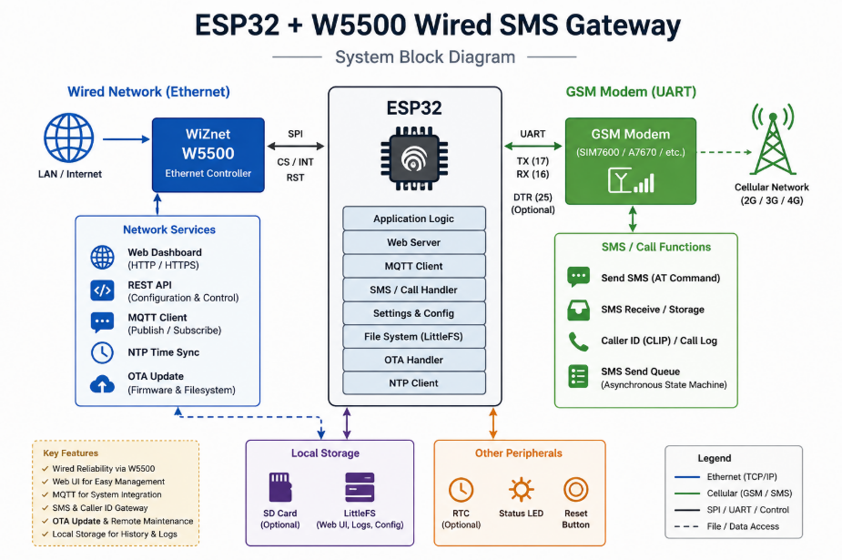
The system therefore works as a bridge between three worlds:
A browser-based operator interface, an MQTT-based automation system, and a GSM-based SMS channel.
When a user sends an SMS from the web dashboard, the request enters the ESP32 through the W5500 Ethernet connection. The web server validates the request and passes it to the GSM modem module. Instead of blocking the whole firmware while the modem sends the message, the system uses an asynchronous queue and state machine. This allows the ESP32 to keep serving the dashboard, maintaining MQTT, parsing modem events, and updating status while SMS transmission is still in progress.
When an SMS request comes from MQTT, the flow is similar. A server, Node-RED flow, IoT platform, or backend application publishes a message to the configured SMS topic. The ESP32 MQTT client receives that payload, converts it into a send request, places it into the SMS queue, and later publishes status or acknowledgement information back to MQTT.
Caller ID handling follows the opposite direction. The GSM modem emits unsolicited result codes such as RING or +CLIP. The ESP32 parses those events, extracts the caller number, stores the event in call_log.json, and can publish the caller information to MQTT. This makes the project useful not only for outgoing alerts but also for logging call attempts from field devices, operators, or alarm systems.
The browser dashboard is served from LittleFS using files under the Data/ directory. The UI is designed as an integrated maintenance surface rather than a single-purpose SMS form. It includes SMS sending, SMS history, call history, contacts, MQTT settings, device settings, OTA update, and an AT command console.
This makes the project closer to a small deployable field gateway than a simple ESP32 demo.
Where WIZnet Fits
The WIZnet product used in this project is the W5500 Ethernet controller.
In this architecture, the W5500 is not a decorative network option. It is the primary wired communication path for managing and integrating the SMS gateway.
The W5500 is responsible for the LAN-side communication used by:
- the web dashboard,
- HTTP API endpoints,
- MQTT broker connection,
- MQTT SMS trigger reception,
- MQTT status and caller ID publishing,
- NTP time synchronization,
- OTA firmware upload,
- filesystem upload,
- remote configuration.
The GSM modem handles SMS and caller events, but the W5500 handles the control and operations network.
This separation is important. SMS gateways are often installed in places where reliability matters more than convenience: factory panels, utility rooms, alarm cabinets, equipment racks, remote monitoring boxes, or building management systems. In those environments, Wi-Fi may be blocked, unstable, overloaded, or prohibited by policy. A wired Ethernet connection through W5500 gives the device a more predictable maintenance and automation path.
The W5500 also makes sense for an MCU-based design because it provides hardware TCP/IP offload. The ESP32 does not need to spend as much application-level effort maintaining a software TCP/IP stack for Ethernet traffic. The W5500 includes its own TCP/IP engine, internal buffering, SPI interface, and multiple socket support. In a project that already needs to manage a web server, MQTT reconnects, GSM modem timing, JSON configuration files, OTA uploads, and local logs, offloading network transport is a practical design choice.
The project notes identify the current hardware connections as:
- ESP32 as the main controller,
- WIZnet W5500 Ethernet module over SPI,
- GSM modem over UART,
- GSM UART RX on
16, - GSM UART TX on
17, - optional DTR control on
25, - W5500 CS/RESET noted as
5, requiring board-level verification.
The W5500 pin note is especially important. If CS and RESET are not correctly separated or configured for the target board, Ethernet initialization may appear inconsistent. Before using the project in a real installation, the schematic and firmware pin definitions should be checked together.
Implementation Notes
The repository source code was not provided directly, so real code snippets cannot be verified or quoted from source files. The notes below are based on the supplied project description. Any code shown here is a conceptual integration example based on common W5500 usage patterns and should be adapted to the actual repository before use.
The project appears to be divided into clear firmware modules.
main.ino is the firmware entry point. Its role is to initialize the platform and keep the main services alive. A typical boot order for this project would be filesystem mount, settings load, Ethernet initialization, web server startup, GSM modem initialization, MQTT configuration load, NTP synchronization setup, and OTA handler registration.
The main loop should avoid long blocking delays. This is important because the ESP32 has to keep several services responsive at the same time. While the GSM modem is sending an SMS, the web UI should still load. While MQTT is reconnecting, modem URC parsing should still continue. While an operator opens the status page, the SMS queue should not be interrupted.
webserver.cpp/.h likely handles the HTTP server, API routes, Basic Auth protection, static file serving from LittleFS, and request parsing for settings, SMS sending, history retrieval, MQTT configuration, AT commands, and OTA pages.
The web server is the human-facing control plane. Operators can use it to send a test SMS, inspect device state, check whether MQTT is connected, confirm modem signal status, and upload firmware or filesystem files. Because /api/* endpoints are protected with HTTP Basic Auth, the web layer also acts as a basic administrative boundary.
gsm_modem.cpp/.h is the most timing-sensitive part of the firmware. GSM modems do not behave like simple serial printers. They require command sequencing, response waiting, prompt detection, timeout handling, and parsing of unsolicited events. For SMS sending, a queue and state machine are more robust than a single blocking function.
A good GSM send flow usually includes:
- accept SMS request from web or MQTT,
- enqueue recipient and message,
- check modem readiness,
- send AT command for SMS mode,
- send recipient command,
- wait for modem prompt,
- write message body,
- send control character,
- wait for final result,
- store success or failure in history,
- publish acknowledgement if MQTT is enabled.
That structure matches the project description: asynchronous queue plus state machine in gsm_modem.cpp.
mqtt_module.cpp/.h handles broker connection, topic subscription, publish events, reconnect behavior, and configuration loading from mqtt_config.json.
MQTT gives the project its automation value. Without MQTT, the device is mainly a browser-operated SMS gateway. With MQTT, it becomes a networked actuator for SMS delivery. A Node-RED flow, SCADA-adjacent system, backend alert service, or IoT platform can publish a JSON payload to the SMS topic and receive acknowledgement or status through return topics.
For example, the intended MQTT usage can be understood like this:
{
  "to": "+821012345678",
  "message": "Compressor alarm: high temperature"
}
The ESP32 receives the payload, validates the destination and message, inserts the job into the GSM send queue, and publishes delivery state or failure information after the modem responds.
ntp_sync.cpp/.h provides time synchronization. This matters because SMS history and caller ID logs are only useful when timestamps are reliable. In an alarm environment, a log entry without accurate time is much less valuable. The W5500 Ethernet connection enables the ESP32 to contact an NTP server after network initialization.
settings.cpp/.h manages runtime configuration. This includes timezone, modem behavior, timeout values, ring count behavior, serial speed, and other operational parameters. A useful detail in the project description is that settings changes are applied immediately where possible. That is important for field maintenance because operators should not need to reflash firmware just to adjust modem timeout or MQTT settings.
ota_update.cpp/.h handles firmware and filesystem upload through /ota. This is a key operational feature. Once an SMS gateway is installed inside a panel or cabinet, physical USB access may be inconvenient. OTA allows firmware updates and UI file updates over the wired Ethernet link.
Data/index.html and Data/js/script.js form the dashboard. The UI includes SMS history, SMS sending, call logs, contacts, MQTT settings, system settings, OTA update, and AT console. This confirms that the project is designed as an integrated appliance-style interface rather than a minimal API-only firmware.
The local data files appear to include:
sms_history.jsonfor sent message records,call_log.jsonfor incoming call or caller ID records,mqtt_config.jsonfor broker and topic settings,- contact or configuration JSON files under
Data/.
The provided API list shows a practical management interface.
Important GET endpoints include:
/api/settings,/api/modem-status,/api/sms-status,/api/sms-history,/api/call-log,/api/mqtt-config.
Important POST endpoints include:
/api/send-sms,/api/contactsor/api/save-contacts,/api/settings,/api/mqtt-config,/api/mqtt-test,/api/set-password,/api/at/send.
The project description also notes two implementation risks that should be mentioned honestly.
First, some frontend configuration and backend routes may not fully match. For example, contact-related endpoints may differ between Data/config.json, frontend JavaScript, and server-side handlers. This should be checked before demonstration or deployment because a route mismatch can make a UI feature appear broken even when the firmware module exists.
Second, the AT console response handling is described as incomplete or partially commented. This does not necessarily affect normal SMS sending, but it matters for diagnostics. If the AT console is shown in a UCC demonstration, it should be presented as a maintenance/debug feature, not as a fully finished modem terminal unless the actual code confirms complete response handling.
Conceptual integration example based on WIZnet ioLibrary
The actual repository code was not provided, so this is not a verified project snippet. It shows the kind of W5500 initialization logic that the project architecture depends on.
#include <SPI.h>
#include <Ethernet.h>

#define W5500_CS_PIN 5

byte mac[] = { 0x00, 0x08, 0xDC, 0x12, 0x34, 0x56 };

void initEthernet() {
  Ethernet.init(W5500_CS_PIN);

  if (Ethernet.begin(mac) == 0) {
    // DHCP failed: production firmware should retry,
    // fall back to static IP, or expose an error state.
    return;
  }

  // At this point the ESP32 can start web, MQTT, NTP, and OTA services.
}
This configuration matters because the W5500 must be initialized before network-dependent services start. The web server, MQTT client, NTP sync module, and OTA handler all depend on the Ethernet interface being ready.
A more complete firmware would also check link status, DHCP result, local IP, reconnect timing, and failure reporting through the dashboard.
void networkServiceLoop() {
  // Keep MQTT alive without blocking GSM modem processing.
  mqttLoop();

  // Continue handling HTTP requests.
  webServerLoop();

  // Keep GSM state machine running independently.
  gsmModemLoop();
}
This second example shows the architectural principle. The firmware should not let MQTT reconnect attempts, SMS sending, web requests, or modem parsing block each other for long periods. The project’s queue and state-machine design is the correct direction for that reason.
Practical Tips / Pitfalls
- Verify the W5500 SPI wiring before debugging firmware. Check MISO, MOSI, SCK, CS, RESET, 3.3 V power, and common ground. A wrong CS pin can look like a software failure.
- Separate W5500 CS and RESET clearly in the schematic and firmware. The supplied notes mention W5500 CS/RESET as
5, but this should be validated for the actual board. - Confirm Ethernet link status before testing MQTT. A successful compile does not prove the cable, switch port, PHY link, DHCP server, or MAC address configuration is correct.
- Use DHCP for fast demonstrations, but prefer static IP or DHCP reservation for field installation. Operators need a predictable dashboard address.
- Keep GSM modem handling asynchronous. SMS sending can take several seconds, and the firmware should still serve the dashboard and process MQTT during that time.
- Put limits on
sms_history.jsonandcall_log.json. LittleFS can fill up if call logs or SMS records grow forever. - Test MQTT reconnect behavior with the broker offline. The gateway should continue local SMS and web functions even when MQTT is unavailable.
- Protect OTA access carefully. Basic Auth is better than an open upload page, but production deployments should also consider network segmentation, stronger authentication, or VPN-only access.
- Validate frontend and backend endpoint names before a UCC demo. A mismatch between JavaScript API calls and server routes can interrupt the demonstration even if the underlying module works.
- Treat the AT console as a diagnostic tool. If response handling is incomplete, avoid presenting it as a fully reliable terminal until the code is finished and tested.
FAQ
Q: Why use WIZnet W5500 for this ESP32 SMS gateway?
A: The W5500 provides a wired Ethernet path for the gateway’s control and maintenance functions. In this project, it supports the web dashboard, HTTP APIs, MQTT connection, NTP synchronization, and OTA updates. This is useful in industrial or facility environments where Wi-Fi may be unstable, restricted, or difficult to maintain.
Q: How does the W5500 connect to the ESP32?
A: The W5500 connects to the ESP32 through SPI. The project notes identify W5500 CS/RESET as pin 5, while the GSM modem uses UART RX 16 and TX 17, with optional DTR on pin 25. The exact W5500 CS and RESET wiring should be confirmed against the board design before use.
Q: What role does the W5500 play in this specific project?
A: The W5500 is the LAN-side transport interface. It carries web UI traffic, API requests, MQTT messages, NTP traffic, and OTA uploads. It does not send SMS directly; SMS is handled by the GSM modem. The W5500 keeps the management and automation network stable while the modem handles cellular messaging.
Q: Can beginners follow this project?
A: Beginners can follow the concept, but implementation requires some ESP32 experience. The developer should understand SPI wiring, UART modem communication, Arduino libraries, JSON configuration files, basic IP networking, MQTT topics, and AT command behavior. The most difficult part is not the W5500 itself, but coordinating web, MQTT, filesystem, OTA, and GSM modem timing in one firmware.
Q: How does W5500 Ethernet compare with ESP32 Wi-Fi for this gateway?
A: ESP32 Wi-Fi is convenient when cabling is not available, but it depends on signal quality, credentials, RF conditions, and access point stability. W5500 Ethernet is better when the gateway is installed permanently and must remain reachable from a local server, Node-RED instance, MQTT broker, or maintenance PC. For an SMS alarm gateway, wired management access is usually easier to trust than wireless access.
Source
Original project link: Not provided.
Source basis: User-provided ESP32-SMS-SRV project description for WIZnet Maker UCC curation.
Curation structure reference:
FAQ structure reference:
License: Not specified.
Tags
#W5500 #WIZnet #ESP32 #Ethernet #SMSGateway #GSMModem #MQTT #LittleFS #OTA #IndustrialIoT #Arduino #CallerID