
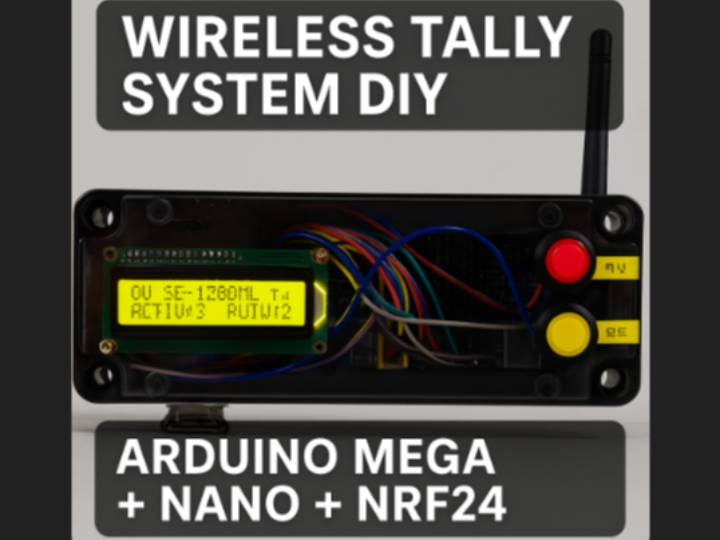
DIY Wireless Tally System(자작 무선 탈리만들기)
A custom DIY wireless tally system built with Arduino Mega(with Ether Shield), Nano, and NRF24, supporting ATEM, Vmix, DataVideo, Sony, and AVMatrix switchers.

Arduino - Arduino Mega 2560
x 1
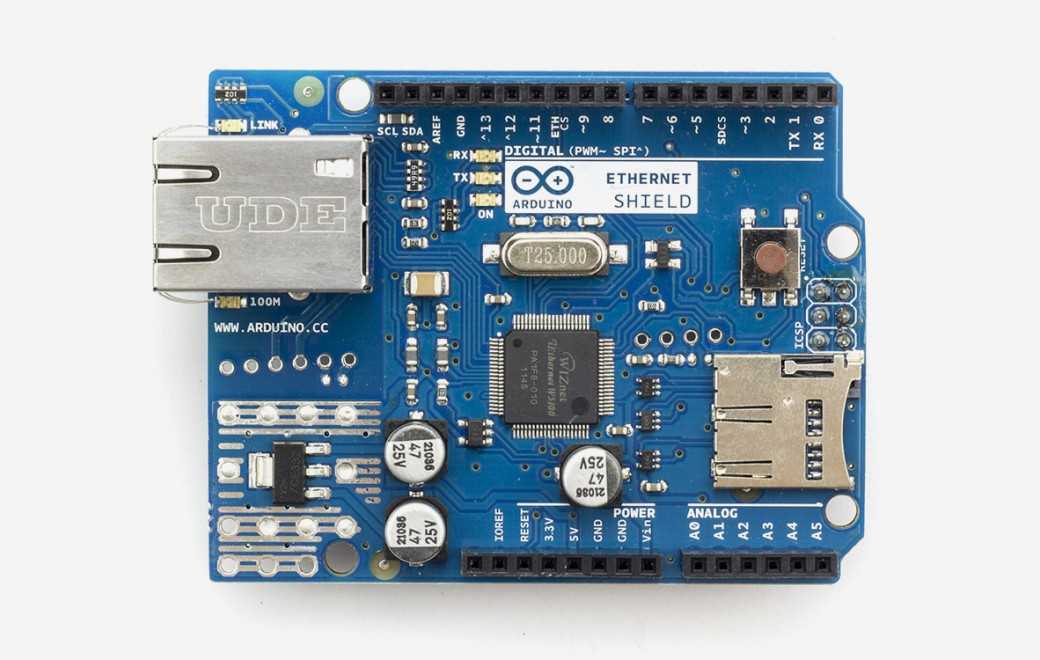
Arduino - Arduino Ethernet Shield
x 1
✔ DIY Wireless Tally System Project (Arduino Mega + Nano + NRF24L01)
by Choi Ki-Hyun
Originally shared in a Korean pro-broadcasting community where live-production directors exchange technical knowledge.
Tally systems are essential in analog switchers and live broadcasting environments.
In this project, I built a fully wireless tally transmitter/receiver system that supports multiple switchers such as Vmix, DataVideo, Sony, AVMatrix, and Blackmagic ATEM, and displays tally status using wireless LED modules.
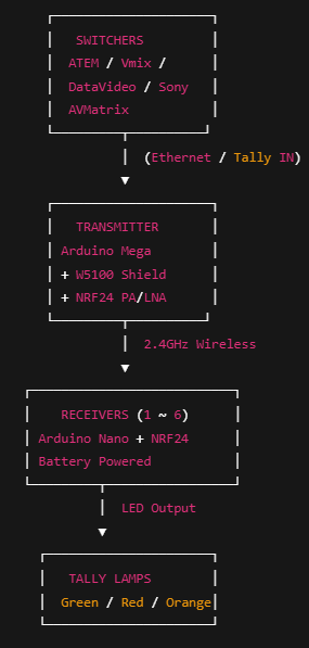
1) System Overview
This project is divided into two main components: Transmitter and Receiver.
✦ Transmitter
Arduino Mega
Arduino Ethernet Shield (W5100) ← highlighted as the network interface
NRF24L01+ PA/LNA (long-range)
✦ Receiver
Arduino Nano
NRF24L01 (3.3V powered)
✦ Communication
2.4GHz NRF24L01 wireless link
Supports Vmix / DataVideo / Sony / AVMatrix / Blackmagic ATEM
Output: G/R Tally Lamp (up to 6 channels)
The transmitter receives tally signals from the switcher and sends them wirelessly.
Each receiver uses an LED module to show Preview (Green) and On-Air (Red) states in real time.
2) Transmitter Details
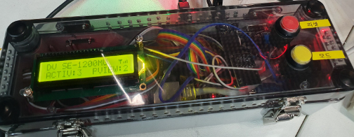
The transmitter is built around an Arduino Mega + W5100 Ethernet Shield,
parsing each switcher’s protocol and sending tally data to the wireless module.
✦ Main Features
Ethernet-based ATEM protocol decoding
Vmix REST API / DataVideo / AVMatrix support
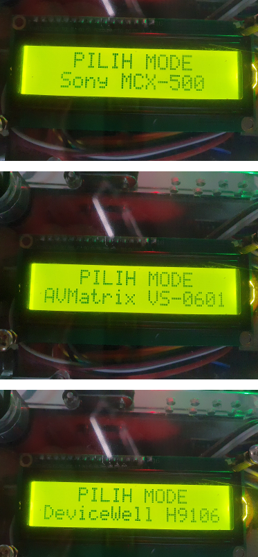
LCD menu for selecting switcher mode
(Sony MCX-500 / DataVideo SE-1200 / AVMatrix VS-0601, etc.)
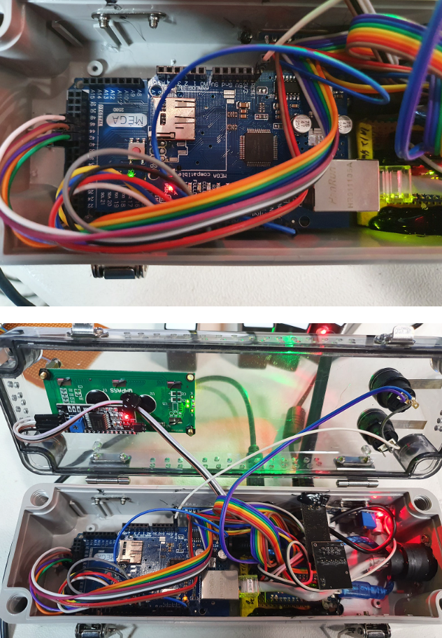
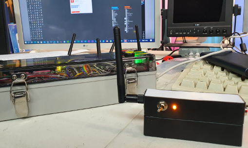
✦ Hardware Configuration
Power switch, reset button, mode selector
D-SUB port → accepts external wired tally signals to retransmit wirelessly
Ethernet port for Vmix/ATEM
External antenna + long-range wireless module
Internal layout: Mega board + NRF24 power module + wiring harness
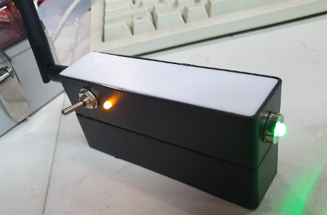
3) Receiver Unit
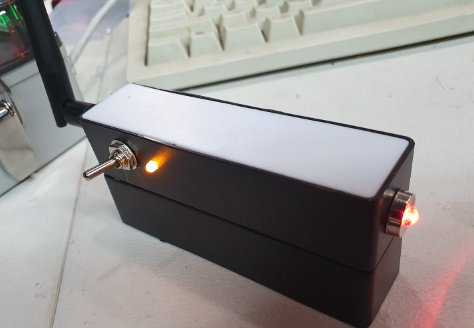
Each receiver displays tally information using a single dual-color LED.
✦ Receiver Features
Arduino Nano
NRF24L01 2.4GHz module
Powered by 18650 battery + USB battery case
Single LED behavior:
Green: Preview
Red: On-Air
Both ON → Orange mixed light
4) Circuit & Reference Material
Reference material used during development:
ATEM Library: https://github.com/kasperskaarhoj/SKAARHOJ-Open-Engineering
Modified schematic & Arduino sketches: Included in attached ZIP
Note: The original reference video had A6/A7 pin numbers swapped, so the schematic was redrawn correctly.
5) Component List
| Category | Parts |
|---|---|
| MCU | Arduino Mega, Arduino Nano |
| Ethernet | Arduino Ethernet Shield(W5100) |
| Wireless | NRF24L01 + PA/LNA (Receiver uses standard NRF24L01) |
| Display | LCD 1602 I2C |
| Resistor | 220Ω (LED current limiting) |
| Power | 18650 battery + USB power case |
| Controls | Toggle switch, push button |
| Others | Glue gun, strong adhesive, LED holders, connectors, hardware |
Associated purchase links are available in the original Korean post.
6) Build Notes & Troubleshooting
● NRF24 Power Sensitivity
The NRF24L01+PA module is very sensitive to noise.
Transmitter operates on a stable 5V module
Receiver runs on regulated 3.3V
Adding 10µF–47µF capacitors greatly stabilizes wireless performance
● T-Bar Signal Issue (ATEM)
Based on the Blackmagic ATEM sketch,
the T-Bar code is occasionally not interpreted correctly.
Cause: internal ATEM protocol value changes + analog slider handling
→ Still investigating; community advice is welcome.
7) Completion & Testing
Full testing was performed with Vmix, DataVideo, and ATEM.
All six channels responded correctly with Preview / On-Air states.
Although only four receivers were assembled, the system architecture supports easy expansion.