
cropdroid-room
Ethernet-based room controller integrating multi-sensor monitoring and relay-driven AC control, exposing lightweight HTTP JSON telemetry.
1. What This Project Actually Does
This project is best understood as a wired room automation node that continuously monitors environmental conditions while controlling multiple AC-powered devices through relay outputs.
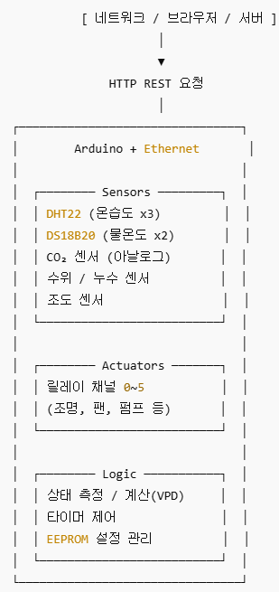
On the sensing side, it aggregates heterogeneous inputs: three DHT22 temperature/humidity sensors for room conditions, two 1-Wire temperature probes for water or pod monitoring, analog leak or water-level sensors, a photoresistor for ambient light, and an analog CO₂ proxy derived from voltage measurements. These values are periodically sampled in a fixed loop cycle and exposed over Ethernet as structured JSON.
On the actuation side, the controller manages six independent relay-switched outlets, each mapped to a digital GPIO pin. Channels can be toggled instantly or activated with a timer-based auto-off mechanism, enabling basic automation patterns such as delayed shutdown of heaters, pumps, or lighting.
Rather than using cloud services or message brokers, the system exposes a minimal REST-like HTTP interface on port 80, making it suitable for local dashboards, industrial HMIs, or supervisory controllers that require predictable, always-available access.
2. Firmware Architecture and Control Logic
2.1 Periodic Loop Design
The firmware follows a deliberately simple architecture built around a 2-second main loop cadence, chosen to respect the minimum sampling interval of DHT22 sensors.
Each loop iteration performs the following sequence:
Read DallasTemperature probes (water/pod temperature)
Read three DHT22 sensors (temperature, humidity, heat index)
Sample photoresistor (light level)
Compute VPD (Vapor Pressure Deficit) using temperature and humidity
Notably, only sensor #0 is used for VPD calculation
Read analog CO₂ voltage and convert it to a ppm-like estimate
Read analog leak/water-level inputs and normalize to percentage
Process HTTP requests and update relay/timer states
This structure prioritizes predictable behavior over throughput, which aligns with room-scale automation rather than high-frequency control.
2.2 Relay Control and Timers
Each of the six relay channels is mapped to a fixed GPIO pin:
Two control modes are supported:
Immediate switching via /switch/{channel}/{position}
Timed activation via /timer/{channel}/{seconds}
Timer-based control is implemented by storing startMillis and intervalMillis for each channel. Auto-off is enforced by comparing elapsed time during each loop iteration. Because enforcement depends on the main loop cadence, the design correctly avoids claiming real-time precision and instead provides best-effort delayed shutdown.
3. Network Behavior and Ethernet Strategy
3.1 Ethernet Initialization with EEPROM Persistence
The network layer uses the Arduino Ethernet library (<Ethernet.h>), with MAC and IP configuration persisted in EEPROM.
If EEPROM is uninitialized, the firmware:
Writes default MAC/IP values
Attempts DHCP using the default MAC
If EEPROM contains valid data:
Reads MAC from bytes 0–5
Reads static IP from bytes 6–9
Initializes Ethernet with fixed addressing
This approach allows field configuration without reflashing firmware, which is a practical requirement for deployed control nodes.
3.2 HTTP JSON Interface
An EthernetServer listens on port 80 and implements minimal request parsing by tokenizing the URL path. Responses are assembled as JSON strings in fixed-size buffers stored in SRAM, with extensive use of PROGMEM to conserve memory on AVR-class MCUs.
Key endpoints include:
/state — full sensor and relay state snapshot
/switch/{channel}/{position} — direct relay control
/timer/{channel}/{seconds} — timed relay activation
/sys — firmware, hardware ID, uptime
/eeprom/{addr}/{value} — low-level configuration
/reset and /reboot — remote lifecycle control
No authentication or authorization is implemented, which is an explicit design tradeoff that must be considered in deployment environments.
4. Relationship to WIZnet Ethernet Hardware (Code-First Interpretation)
The firmware includes <Ethernet.h> and relies on the standard Arduino Ethernet stack. In the Arduino ecosystem, this library is typically backed by WIZnet W5x00-family Ethernet controllers via Ethernet shields or modules.
However, the source code does not explicitly name a specific chip (e.g., W5100 or W5500), and no BOM text is provided. Therefore, it is technically accurate to state:
This project implicitly targets WIZnet-based Ethernet hardware through the Arduino Ethernet library, without binding itself to a specific W5x00 variant.
From an architectural standpoint, this design aligns well with WIZnet’s hardware TCP/IP approach:
TCP/IP processing is offloaded from the MCU
SRAM usage remains low compared to software stacks such as LwIP
Wired Ethernet ensures stable, deterministic connectivity for always-on control nodes
If optimized further, the same firmware model could benefit from:
W5500 for larger internal buffers and multi-socket handling
W6100 to extend the REST interface into IPv6 environments
W55RP20 to consolidate MCU and Ethernet into a single industrial-grade component
These are conceptual optimization paths, not claims about the current implementation.
5. Why This Design Matters in Practice
This project demonstrates a pragmatic approach to room-scale industrial or maker automation:
Wired Ethernet avoids the variability and recovery issues common in Wi-Fi
Simple HTTP+JSON lowers integration barriers
Sensor-to-actuator latency is bounded and predictable
EEPROM-backed configuration supports field deployment
The system remains understandable, debuggable, and maintainable
Rather than chasing complexity, it focuses on reliability and determinism, which are often more valuable in real installations.
FAQ
Q1: Why use Ethernet instead of Wi-Fi for this controller?
A wired Ethernet connection provides stable latency and continuous availability, which is important for relay control and monitoring tasks that should not fail due to RF interference, reconnection delays, or access point issues. This project prioritizes predictable behavior over mobility.
Q2: What role does WIZnet hardware play in this architecture?
Although the code does not specify a chip, the Arduino Ethernet library is commonly backed by WIZnet W5x00 controllers. These devices offload TCP/IP processing in hardware, allowing the MCU to focus on sensor reading and control logic with minimal RAM usage.
Q3: Is the CO₂ measurement a calibrated sensor reading?
No. The CO₂ value is derived from a simple analog voltage conversion and linear approximation. It should be treated as a relative or proxy indicator, not as a calibrated NDIR CO₂ measurement suitable for regulatory or scientific use.
Q4: How accurate are the timer-based relay controls?
Timer enforcement depends on the main loop execution cycle, which runs approximately every two seconds. This design is appropriate for delayed shutoff and safety timers but is not intended for high-precision real-time control.
Q5: Is this project suitable for industrial deployment?
Architecturally, yes—especially in controlled networks. However, production deployment would require additional considerations such as authentication, electrical certification, enclosure design, and fail-safe behavior.
Tags
#Ethernet #RoomController #RelayControl #IndustrialIoT #Arduino #WIZnet #HTTPJSON
이더넷 기반 환경 모니터링 및 릴레이 제어 룸 컨트롤러는 어떻게 구현되는가?
1. 이 프로젝트의 본질
이 시스템은 유선 이더넷 기반의 룸 자동화 노드로 볼 수 있습니다.
온도, 습도, 수온, 누수, 조도, CO₂ 유사 지표를 지속적으로 수집하면서, 6개의 릴레이 출력으로 히터, 펌프, 조명 등 AC 부하를 제어합니다.
이 코드는 실시간 스트리밍 시스템이 아닌 적절한 타이밍에 즉각 수행하는 제어용 실시간 시스템입니다. 스마트팜에서 쓰이는 VPD (Vapor Pressure Deficit)기술을 사용했고, 클라우드의 사용이나 높은 난이도의 스택 없이 실시간 성이 보장되고 예측 가능한 시간에 작동하는 구조 현장 장비 제어에 최적화 되어 있습니다.
센서 데이터는 2초 주기의 루프에서 수집되며, 모든 상태는 로컬 네트워크를 통해 JSON 형태로 제공됩니다. 클라우드 의존 없이도 HMI, PLC, 상위 제어기와 직접 연동이 가능합니다.
2. 실제 설치 환경은 이런 모습이다
이 장치는 보통 아래 같은 곳에 설치됩니다.
(1) 스마트팜 / 재배실
(2) 실험실 환경 제어
(3) 서버실 보조 모니터링
(4) 수경재배 시스템
연결된 장비:
온습도 센서 (3곳)
물 온도 센서 (2곳)
CO₂ 센서
수위 / 누수 센서
조도 센서
릴레이 6채널 (조명, 팬, 펌프 등)
3. 내부 구조 한눈에 보기 (텍스트 블록도)
4. “웹 서버”로 운용하는 프로젝트
아두이노가 80번 포트 웹 서버로 동작합니다.
즉, 브라우저나 서버에서:
형태로 접근합니다.
👉 별도 앱 없이도 REST API로 제어 가능
5. 가장 많이 쓰는 기능 3가지
- 현재 상태 조회
온도 / 습도
CO₂ 농도
물 온도
수위 / 누수
조도
릴레이 상태
➡️ 모니터링용
- 장비 ON / OFF
예:
조명 ON
팬 OFF
➡️ 원격 수동 제어
- 타이머 자동 제어
예:
→ 2번 릴레이를 30초만 켰다가 자동 종료
➡️ 펌프·밸브 제어에 최적
6. 이 코드가 “잘 만든 이유”
✔️ 센서 + 제어 + 네트워크 통합
✔️ 메모리 절약 (PROGMEM 사용)
✔️ 실시간 데이터 + 제어 분리
✔️ 서버 / 모바일 / 자동화 시스템 연동 쉬움
즉,
취미용 예제가 아니라 실제 운용 가능한 구조
7. 한 문장 요약 (확실한 정의)
“이 코드는 아두이노를 웹 기반 환경 제어기로 만들어
공간의 상태를 실시간으로 측정하고
전기 장비를 원격·자동 제어하기 위한 펌웨어다.”
FAQ (한국어)
Q1. 왜 Wi-Fi 대신 이더넷을 사용했나요?
유선 이더넷은 무선 간섭, 재연결 문제 없이 안정적인 지연 특성을 제공합니다. 릴레이 제어와 같이 실패하면 안 되는 작업에 더 적합합니다.
Q2. WIZnet 칩은 이 프로젝트에서 어떤 역할을 하나요?
코드에 명시되지는 않지만, Arduino Ethernet 라이브러리는 보통 WIZnet 기반 하드웨어를 사용합니다. 이를 통해 TCP/IP 처리를 MCU 외부에서 수행할 수 있습니다.
Q3. CO₂ 값은 정확한 측정인가요?
아닙니다. 단순한 아날로그 전압 기반 근사치이며, 보정된 NDIR 센서로 간주해서는 안 됩니다.
Q4. 타이머 제어는 얼마나 정확한가요?
메인 루프 주기에 의존하므로 초 단위 정밀 제어는 아닙니다. 안전 차단이나 지연 OFF 용도로 적합합니다.
Q5. 산업 현장에 바로 사용할 수 있나요?
구조적으로는 가능하지만, 실제 양산이나 산업 적용을 위해서는 보안, 인증, 전기 안전 설계가 추가로 필요합니다.