
Brew_Arduino
This project presents an automated brewery control system using Ethernet-based PC-to-controller communication, integrating temperature, flow, and actuator ctrl.
1. What This Project Is — In Practical Terms
This project represents a professionally engineered, fully automated brewing control system, designed and built from the ground up rather than assembled from off-the-shelf automation modules.
At its core, the system automates a multi-kettle brewing setup (HLT, MLT, and boil kettle) by continuously reading temperatures and flow rates, then controlling heating elements, gas burners, pumps, and solenoid valves based on feedback from a PC-based brewing program. The design explicitly avoids black-box controllers by implementing custom hardware, firmware, and PC software, enabling full transparency and extensibility.
A key architectural decision is the use of Ethernet as the primary communication channel between the PC (a small NUC-class computer) and the brewing electronics. USB is retained only for debugging. This separation allows the brewing system to operate as a stable, network-connected industrial-style control node rather than a fragile, tethered USB device.
2. System Architecture Overview

Image generated by Gemini.
이미지는 제미니가 생성했습니다.
2.1 PC ↔ Controller Communication
The brewing PC runs a dedicated control application responsible for:
Executing PID temperature control
Logging all commands and sensor data
Orchestrating the brewing process (mashing, boiling, cooling)
Communication with the brewing electronics occurs via:
Ethernet (primary) for operational control
USB (virtual COM port) for debugging and commissioning
The serial protocol is deliberately simple and human-readable (e.g., A0, Bxx yyy, Vxxx), which makes the system testable with standard terminal software and easy to diagnose in the field.
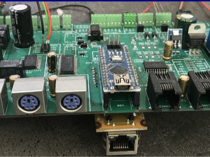
2.2 Microcontroller Core
The brewing electronics are centered around an Arduino Nano (ATmega328P) mounted on a custom main PCB. The microcontroller performs three critical roles:
Sensor acquisition (temperature, flow)
Actuator control (relays, valves, burners)
Deterministic execution of commands received from the PC
Rather than pushing complex logic into the MCU, higher-level decisions remain on the PC. This division of responsibility simplifies firmware while maintaining robust control behavior.
3. Sensor Subsystem Design
3.1 Temperature Measurement Strategy
The system supports up to six temperature sensors, using a hybrid approach:
I2C digital sensors (LM92) for high accuracy (±0.33 °C)
One-Wire sensors (DS18B20) for mechanical robustness and ease of mounting
To improve reliability:
Each critical vessel (HLT, MLT) uses two independent sensors
Measurements can be averaged or used redundantly
Automatic fallback occurs if one sensor fails
One notable design choice is the use of hardware One-Wire bridges (DS2482-100) instead of software timing. This eliminates microsecond-level timing sensitivity and significantly improves long-term reliability.
3.2 Flow Measurement
Four FS300A flow sensors are used to measure liquid transfer between vessels and through the counterflow chiller. The Arduino counts pulses (~330 pulses per liter), enabling:
Accurate volume tracking
Real-time flow verification
Calibration down to ~0.1 L resolution
This allows the brewing program to reason about both temperature and mass transfer, which is critical for repeatable brewing.
4. Actuator Control and Power Electronics
4.1 High-Voltage Switching (230 V AC)
All high-power components (pumps, heaters, burners) are switched via:
Triac-based circuits (BTA25H)
Zero-cross detection using MOC3043 opto-triac drivers
Galvanic isolation between logic and mains power
Thermal protection is implemented by monitoring triac temperature and disabling outputs if predefined thresholds are exceeded. This is an industrial-grade safety practice rarely seen in hobby systems.
4.2 Gas Burner Control
Both non-modulating and modulating gas valves are supported:
Non-modulating valves use relay-based 24 V AC switching with hysteresis
Modulating valves are driven by 25 kHz PWM, generated directly by the ATmega328P Timer1
The PWM duty cycle is derived from PID output values (0–100%), allowing fine-grained heat control that closely matches professional brewing systems.
4.3 Solenoid Valve Matrix
Eight 24 V DC solenoid ball valves are controlled using:
MCP23017 (16-bit I2C IO expander)
TD62783 Darlington driver arrays
Resettable PTC fuses for output protection
This design mirrors PLC-style output modules, emphasizing fault containment and serviceability.
5. Ethernet as the System Backbone
Although the documentation focuses on functionality rather than specific Ethernet chip models, the design clearly assumes an Arduino Ethernet stack and wired networking as a first-class citizen.
From an architectural standpoint, Ethernet provides:
Deterministic latency for control commands
Stable, long-duration connections
Easy integration with PCs and local networks
Independence from USB cable length and host stability
This aligns strongly with industrial automation principles, where wired Ethernet is preferred over wireless solutions for safety-critical and long-running processes like brewing.
Importantly, the documentation does not explicitly name a WIZnet chip. Therefore, Ethernet usage should be interpreted as library- and architecture-level, not as a claim about a specific controller variant.
6. Why This Project Matters Technically
This system demonstrates what happens when a brewing project is treated as a control engineering problem, not a hobby experiment:
Clear separation of sensing, control, and actuation
Redundant measurements for critical parameters
Hardware-assisted timing and isolation
Deterministic Ethernet-based communication
Full observability through logging and diagnostics
The result is a system that behaves less like a DIY gadget and more like a custom-built industrial controller adapted for brewing.
FAQ
Q1: Why is Ethernet used instead of USB-only communication?
Ethernet allows the brewing electronics to operate as a networked control node rather than a peripheral device. This improves stability, enables long cable runs, and avoids common USB issues such as enumeration failures or host-side resets during long brewing sessions.
Q2: What role does the Arduino Nano play in this system?
The Arduino Nano acts as a deterministic real-time interface between sensors, actuators, and the PC. It executes low-level control tasks and timing-sensitive operations while delegating high-level process logic to the PC software.
Q3: How is reliability achieved in temperature measurement?
Critical vessels use two independent temperature sensors with different protocols (I2C and One-Wire). The system can average readings or automatically fall back if one sensor fails, ensuring continued operation.
Q4: Is this system comparable to industrial PLCs?
Conceptually, yes. While it is built from discrete components, the architecture mirrors PLC design patterns: isolated IO, deterministic communication, modular subsystems, and explicit fault handling.
Q5: Is this design suitable for others to replicate?
Yes, provided the builder has sufficient electronics experience. The documentation, schematics, and BOM are detailed enough for technically skilled users to reproduce or adapt parts of the system safely.
Original Source
Project: Emile’s Fully Automated Brewery
Author: Emile van de Logt
Last Update: 2023-08-04
Source Files: Brew_Arduino (GitHub)
Tags
#Ethernet #BrewAutomation #IndustrialIoT #ArduinoNano #ProcessControl #HERMS #ControlEngineering
🇰🇷 한국어 버전
이더넷 기반 완전 자동화 양조 시스템은 어떻게 동작하는가?
요약 (51단어)
이 프로젝트는 이더넷 기반 PC-컨트롤러 통신을 중심으로 설계된 완전 자동화 양조 시스템을 설명합니다. Arduino Nano, 전용 PC 소프트웨어, 맞춤형 전자회로를 통해 온도·유량 측정과 액추에이터 제어를 통합하여 HERMS/RIMS 양조 공정을 안정적으로 자동화합니다.
1. 이 프로젝트의 본질
이 시스템은 기성 PID 컨트롤러를 조합한 취미용 장비가 아니라, 제어공학 관점에서 설계된 자동화 양조 플랫폼입니다.
PID는 제어 공학에서 쓰이는 하나의 알고리즘으로써, “목표값(Setpoint)”과 “현재 측정값”의 차이(오차)를 기반으로 시스템을 안정적으로 제어하는 알고리즘입니다.
PC는 양조 레시피 실행과 PID 계산을 담당하고, 전자 제어부는 센서 수집과 액추에이터 제어를 담당합니다. 두 시스템은 이더넷을 통해 지속적으로 연결되어 있으며, USB는 디버깅 용도로만 사용됩니다.
2. 전체 아키텍처
2.1 PC와 제어 전자장치의 분리
PC:
PID 제어 수행
데이터 로깅
전체 공정 시퀀싱
전자 제어부:
센서 데이터 수집
릴레이·밸브·버너 제어
명령을 결정론적으로 실행
이 구조는 장시간 운전에도 안정적인 동작을 보장합니다.
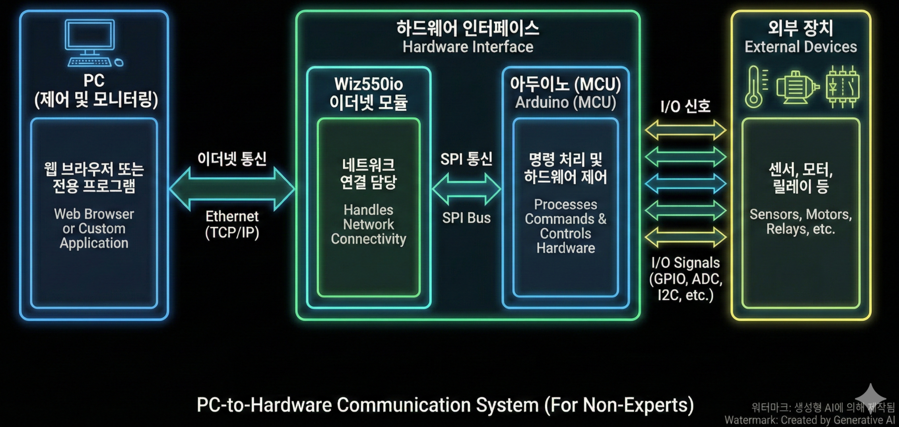
Image generated by Gemini.
이미지는 제미니가 생성했습니다.
3. 센서 설계 철학
3.1 온도 센서 이중화
HLT와 MLT에는 서로 다른 방식의 센서가 이중으로 설치됩니다:
I2C LM92 (고정밀)
One-Wire DS18B20 (기계적 신뢰성)
한 센서가 실패해도 자동으로 대체 측정이 가능하도록 설계되었습니다.
3.2 유량 측정
FS300A 유량 센서를 사용해 펄스 기반으로 유량을 계산하며, 0.1L 수준까지 보정이 가능합니다. 이는 실제 양조 공정에서 매우 중요한 정확도를 제공합니다.
4. 액추에이터 및 전력 제어
4.1 230V AC 스위칭
트라이액(BTA25H)
제로 크로싱(MOC3043)
갈바닉 절연
온도 기반 보호 로직
가정용 DIY 시스템에서는 보기 드문 산업적 설계입니다.
4.2 가스 버너 제어
비변조: 릴레이 + 히스테리시스
변조: 25kHz PWM (MCU 타이머 직접 생성)
PID 출력이 실제 열 출력으로 자연스럽게 매핑됩니다.
4.3 솔레노이드 밸브 제어
PLC와 유사하게 I2C IO 확장기 + 드라이버 어레이 + PTC 보호를 사용해 8개의 밸브를 안정적으로 제어합니다.
5. 왜 이더넷인가?
이 시스템은 무선이나 USB 중심 설계가 아닌, 유선 이더넷 기반 제어 노드라는 점이 핵심입니다.
지연 시간 예측 가능
장시간 연결 안정성
PC 및 네트워크 통합 용이
이는 산업 자동화에서 일반적으로 채택되는 접근 방식입니다.
6. 기술적으로 의미 있는 이유
이 프로젝트는 “취미용 자동화”를 넘어:
제어 분리
센서 이중화
하드웨어 타이밍 보조
전력 안전 설계
전체 시스템 가시성
을 갖춘 엔지니어링 중심 설계 사례입니다.
FAQ (한국어)
Q1. 왜 USB만 쓰지 않고 이더넷을 사용했나요?
USB는 장시간 운전 시 불안정해질 수 있습니다. 이더넷은 제어 노드를 독립 장치로 만들어 안정성과 확장성을 제공합니다.
Q2. Arduino Nano의 역할은 무엇인가요?
센서와 액추에이터를 직접 제어하는 결정론적 인터페이스 역할을 하며, 고수준 로직은 PC에 맡깁니다.
Q3. 온도 측정 신뢰성은 어떻게 확보했나요?
서로 다른 방식의 센서를 이중으로 사용해 오류 발생 시 자동 대체가 가능하도록 설계했습니다.
Q4. PLC와 비교할 수 있나요?
구조적으로는 매우 유사합니다. 다만 범용 부품으로 직접 구현한 맞춤형 PLC라고 볼 수 있습니다.
Q5. 일반 사용자도 따라 만들 수 있나요?
전자 회로와 전력 제어에 익숙하다면 가능합니다. 문서와 BOM이 매우 상세하게 제공됩니다.