
Energy Monitoring & Controlling System for a Smart Home
The device helps to monitor voltage, current, power, frequency and energy consumption of house in real time and control appliances remotely.
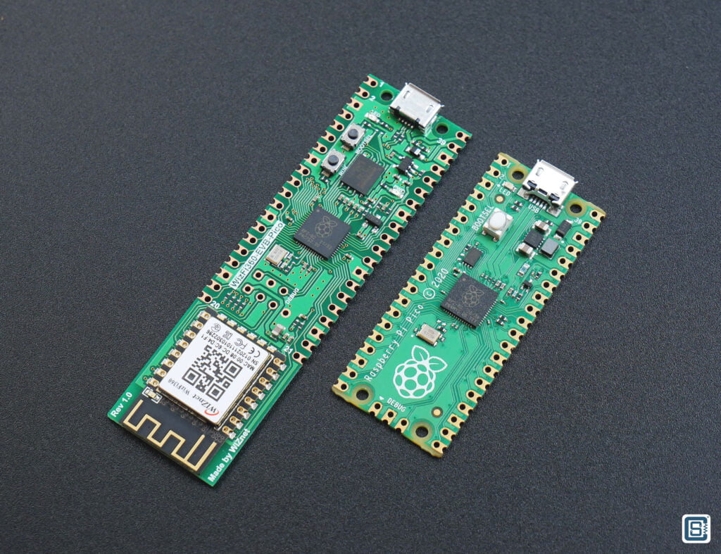
WIZnet - WizFi360-EVB-Pico
x 1
The main part or brain of the system. It collects the sensor data, sends the data to cloud and control the appliances.

seeed - Grove - 4-Channel SPDT Relay
x 1
This relay module is used to control high voltage AC/DC appliances from the WizFi360-EVB-Pico Board. Any generic relay module will work.

seeed - Grove - OLED Display 1.12'' V2
x 1
The I2C OLED display is used to display the important information and parameters.
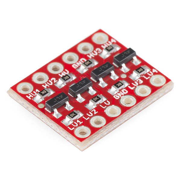
sparkfun - SparkFun Logic Level Converter - Bi-Directional
x 1
Logic level converter is used to connect 5V logic signal with 3.3V GPIO of WizFi360 board

dfrobot - Gravity: Analog AC Current Sensor
x 1
Analog non-invasive current sensor is used to measure current drawn by the applances.
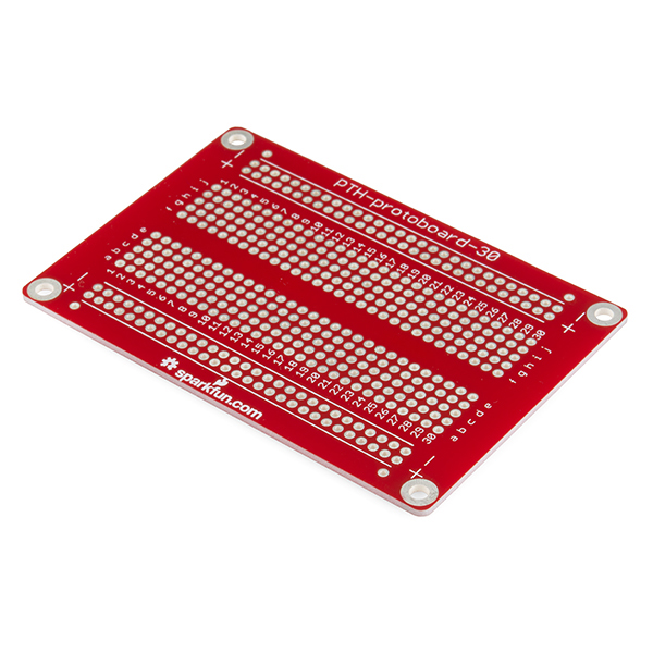
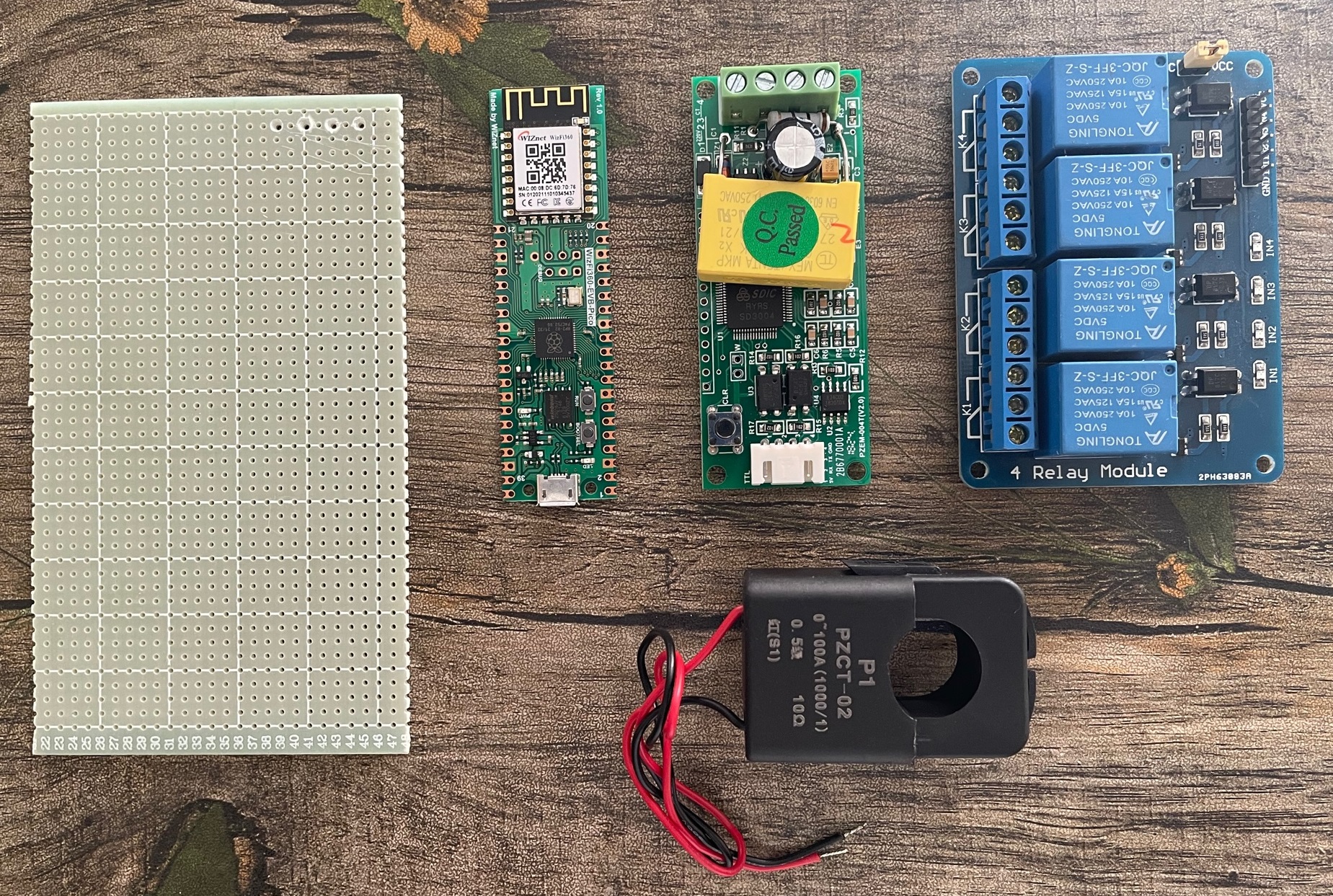
sparkfun - SparkFun Solder-able Breadboard
x 1
Any generic perfboard will be ok.

Arduino - Arduino IDE
x 1
Arduino IDE is used to develop the firmware for the system.
Ubidots - Ubidots
x 1
For cloud monitoring & dashboard
What problem I am going to solve
The world is going through one of the worst energy crises in recent times. The 2008 economic meltdown and the consequent high oil and food prices were relatively short-lived. The Covid pandemic and then the Russia-Ukraine war have kept all energy prices very high for a long time.
This unprecedented long period of high energy prices and the supply shortage is exerting tremendous pressure on all economies – developed, developing, and poor countries are facing a serious cost-of-living challenge.

My country Bangladesh is going through a severe energy crisis. Every area in the country goes through 1-6 hours of load-shedding in urban areas and 11-13 hours in rural areas daily. Because of the high fuel prices in the international market, no one seems to see any solution to this energy crisis in the here and now. But household on-grid solar systems could bring an end to this crisis but it is not affordable for most people in Bangladesh.
In this situation, we have no luxury to waste electricity.
Reducing energy use and waste is mandatory in the current situation and as well as good for the environment. Measuring and monitoring your home’s energy consumption is the first step toward finding ways to decrease it.
While almost every residence has an electric meter, it usually only shows total household energy (kWh) consumed, although some include instantaneous power being used (kW). And the meter is usually placed where it is convenient for the utility—not for you—to read. But conservation-minded homeowners and renters can choose from several products that measure and record electricity consumption to reveal the energy hogs.
If you want to use energy data to help reduce usage and waste or convince other household members to adopt energy-saving behaviors, my Smart Home Energy Monitoring & Controlling System is for you. My project deals with this problem in a simple and effective way by auditing power & energy usage which can be used in homes and industries.
Features of the system
The system will sense the current and voltage and calculate the following parameters
- Active Power
- Reactive Power
- Apparent Power
- Frequency
- Power Factor
- Energy Consumption
and sends all these parameters to the cloud through WiFi. The user can monitor the active devices and control the appliances remotely using mobile app or web dashboard.
Some Basics of Electrical Power & Energy
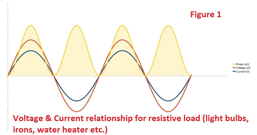
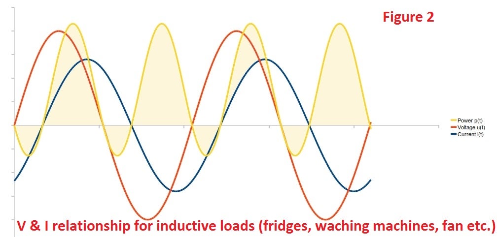
From both voltage, current and power graphs above (figure 1, 2) at mains frequency the power draw fluctuates 50/60 times a second, for us humans we can't keep up with change at this speed and so we have a more useful value for power: the average of the instantaneous power which we call real power! (or active power).
Real power is often defined as the power used by a device to produce useful work. Looking at the graph above the positive bits are power going to the load from the supply and the negative bits are power going back from the load to the supply, the power that was actually used by the load the power going to minus the power going back is the real power.
Reactive power (or imaginary power) is a measure of the power going back and forth between the load and the supply that does no useful work.
Another useful measure of power is Apparent Power which is the product of the Root-Mean-Squared (RMS) average of the Voltage and the RMS average of the Current. For purely resistive loads real power is equal to apparent power. But for all other loads, real power is less than apparent power. Apparent power is a measure of the real and reactive power but it is not an algebraic sum of the two, as the sum of the two does not take into account phase differences.
Relationship between real, reactive, and apparent power for ideal sinusoidal loads:
- Real Power = Apparent Power x cosΦ
- Reactive Power = Apparent Power x sinΦ
cosΦ is also known as the power factor.
In AC circuits, the power factor is the ratio of the real power that is used to do work and the apparent power that is supplied to the circuit. The power factor can get values in the range from 0 to 1. When all the power is reactive power with no real power (usually inductive load) - the power factor is 0.
We can calculate the power factor from the following equation:
- Power Factor = Real Power / Apparent Power
but the relationship
- (Apparent Power)2 = (Real Power)2 + (Reactive Power)2
which is true for pure sine waves is no longer correct, neither is power factor = cosΦ, since the effects of higher order harmonics in both voltage and current waves must be considered.
Calculation of Power & Energy
AC Voltage and current continually alternate, as the name suggests, if we draw a picture of the voltage and current waveform over time, it will look something like the image above (depending on what's using power - the current waveform - blue in the diagram below - is what you get if you look at a typical laptop power supply. There's an incandescent light bulb in there as well).
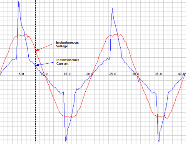
The image was made by sampling the mains voltage and current at high frequency, which is exactly what I do on my project. I will sample instantaneous voltage and current (50 samples per 20ms). Though a higher sampling rate increases the accuracy - we're limited by the Edison Arduino analog read command and calculation speed).
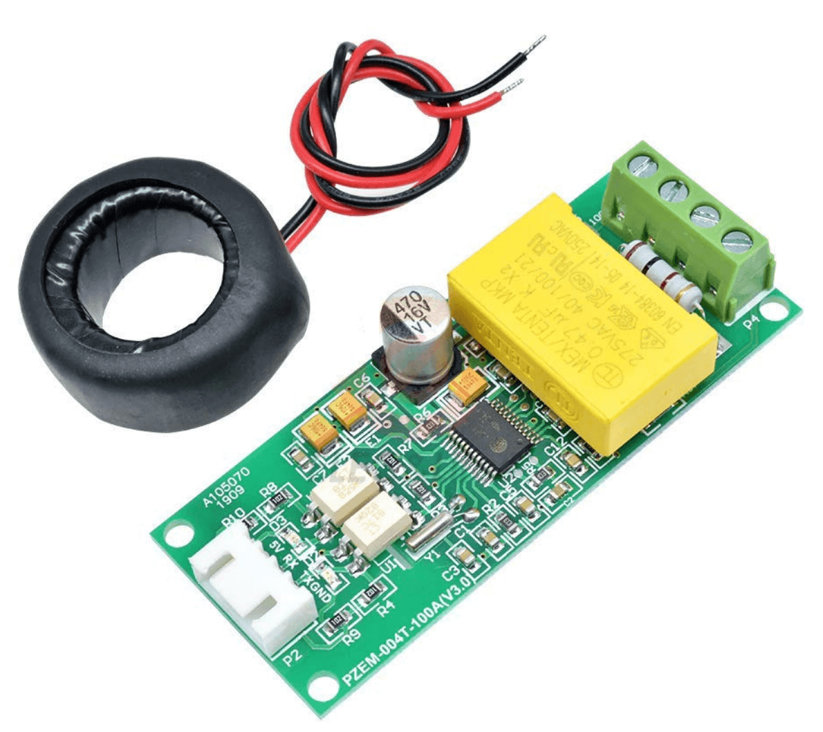
Peacefair PZEM-004T Energy Monitor
The module is used to measure Voltage, Current, Power, Energy, Power Factor, Frequency and Energy consumption without any calculation. It takes the voltage and current readings from CT & PT and does all the calculations for you.
Manufacturer (optimistic) specifications
| Function | Measuring range | Resolution | Accuracy | |
|---|---|---|---|---|
| Voltage | 80~260V | 0.1V | 0.5% | |
| Current | 0~10A or 0~100A* | 0.01A or 0.02A* | 0.5% | |
| Active power | 0~2.3kW or 0~23kW* | 0.1W | 0.5% | |
| Active energy | 0~9999.99kWh | 1Wh | 0.5% | |
| Frequency | 45~65Hz | 0.1Hz | 0.5% | |
| Power factor | 0.00~1.00 | 0.01 | 1% |
This module provides data through a UART port using Modbus. So we must connect this with the WizFi360 Pico through a UART port.
If you want to know the details about the energy monitor module you may visit the following link. https://innovatorsguru.com/ac-digital-multifunction-meter-using-pzem-004t/
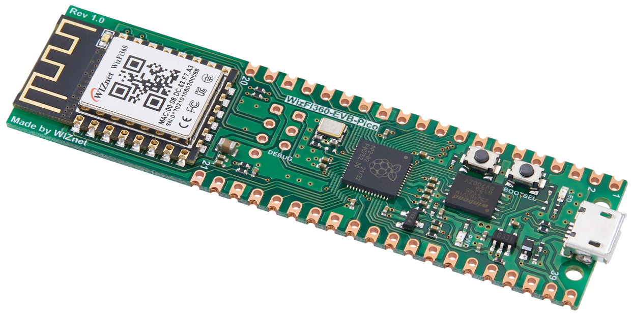
WizFi360-EVB-Pico
WizFi360-EVB-Pico is based on Raspberry Pi RP2040 and adds Wi-Fi connectivity using WizFi360. It is pin compatible with Raspberry Pi Pico board and can be used for IoT Solution development.
The Raspberry Pi Pico and the RP2040 microcontroller have become the most trending names in the maker space. It is no surprise why a product gets adopted so widely and so fast when that product is cheap and feature-packed. RP2040 is a generic ARM Cortex-M0+, dual-core 32-bit microcontroller with so many nifty features which make it a straight grab for any maker or hobbyist.
Pinout of WizFi360-EVB-Pico
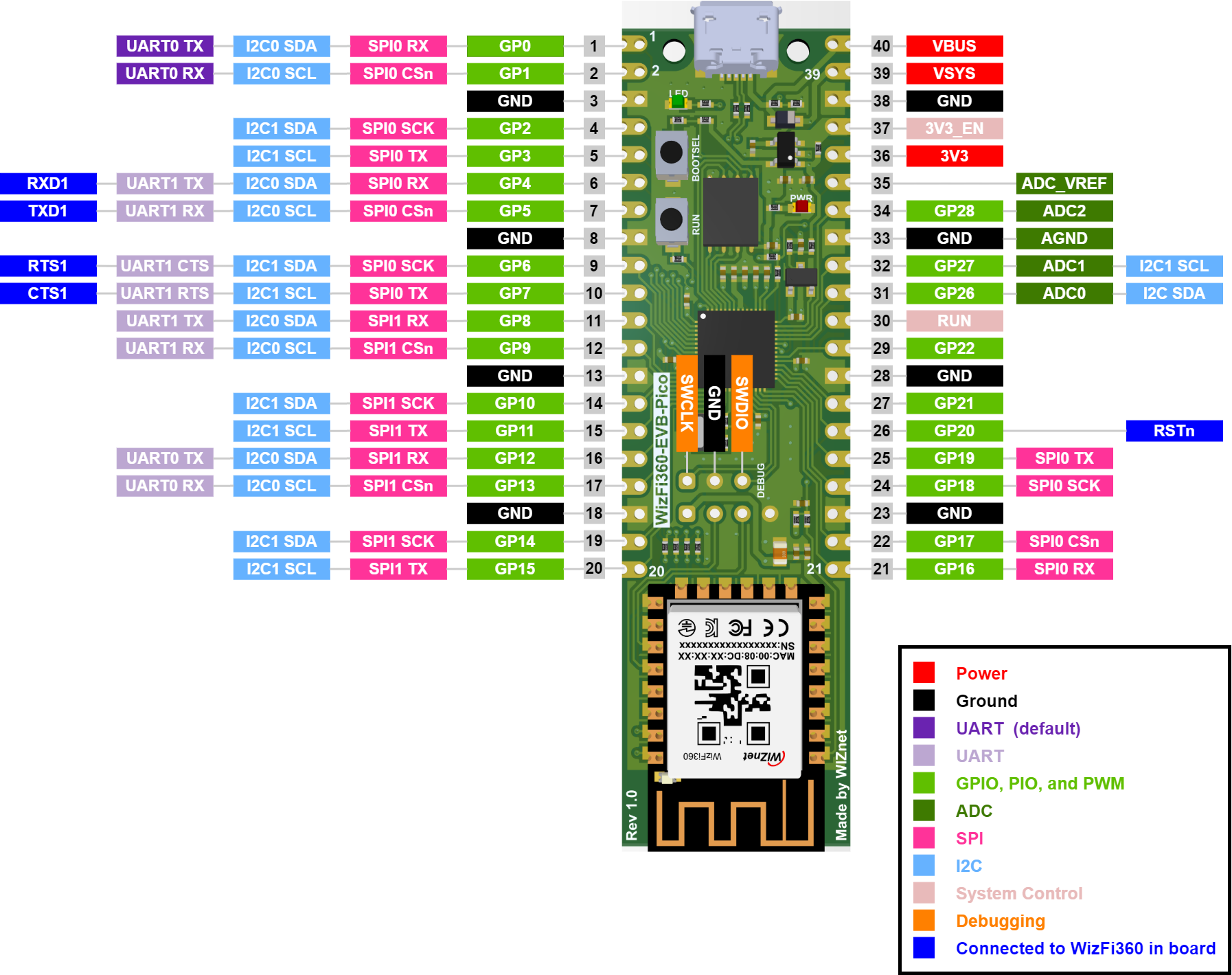
WizFi360-EVB-Pico pinout is directly connected to the GPIO of RP2040 as shown in the picture above. It has the same pinout as the Raspberry Pi Pico board. However, GPIO4, GPIO5, GPIO6, GPIO7, GPIO20 are connected to WizFi360 inside the board. These pins enable UART communication with WizFi360 to use Wi-Fi function. If you are using the Wi-Fi function, these pins cannot be used for any other purpose.
If you want to know how to get started with the WizFi360-EVB-Pico you may follow this excellent guide.
Hardware Preparation & Connection
For making the system first you need to collect all the necessary hardware mentioned in the components list provided at the beginning.
First I placed the energy monitor module in the perfboard with glue and soldered the female pin header according to the size of the WizFi360-Pico board as shown in the image below.
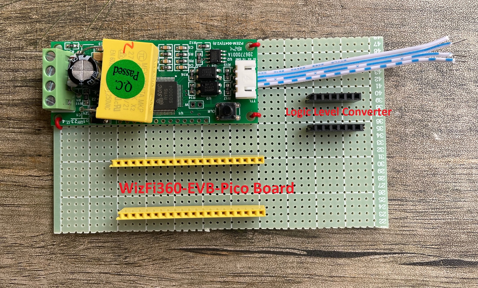
I also placed female pin headers for the logic level converter. The energy monitor module provides the data through the UART port and the logic level of the output is 5V. But the WizFi pico board is not 5V compatible. So you must use a logic level converter to protect the WizFi360 board from damage and malfunction.
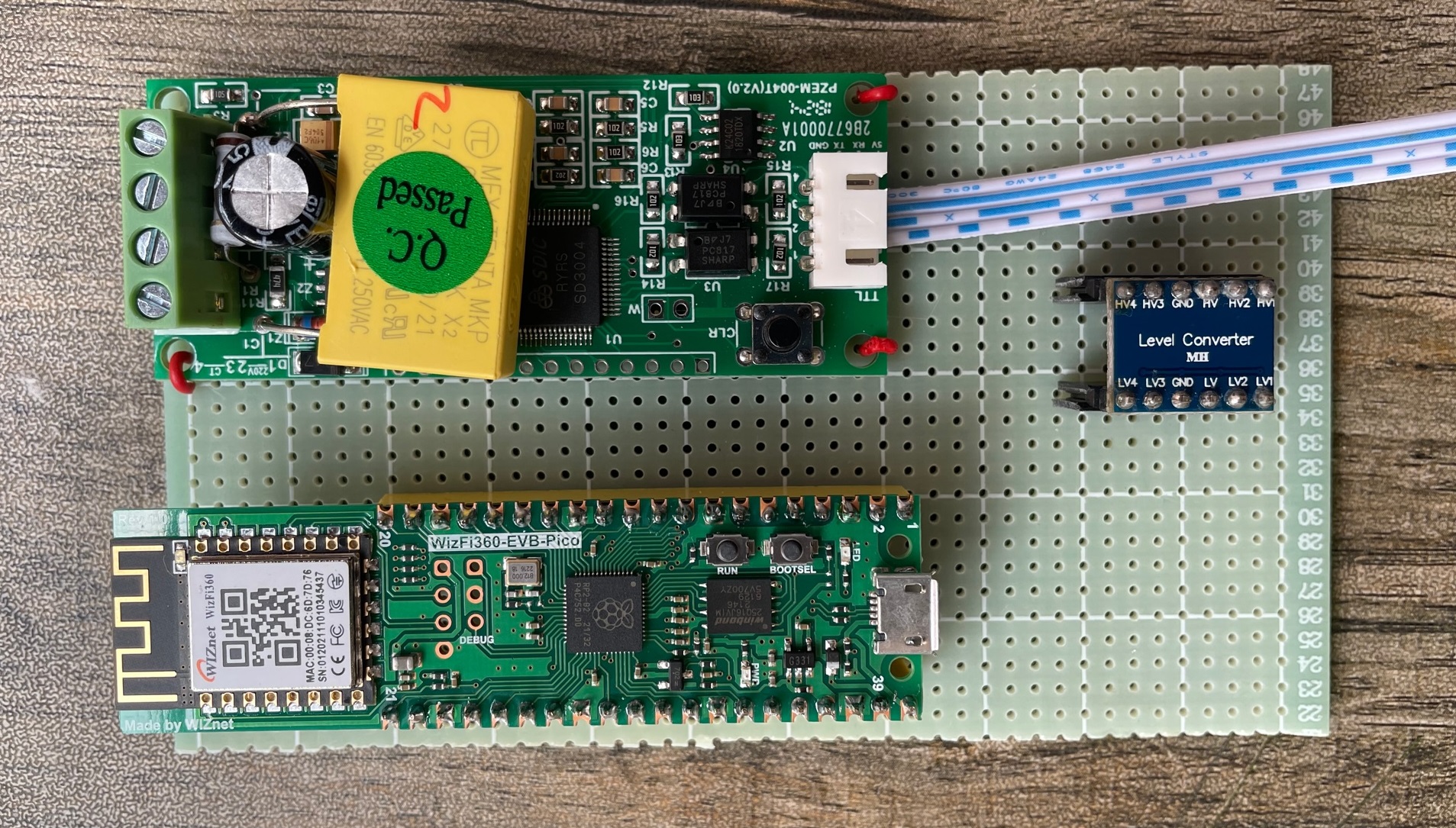
The Pico has two hardware UART. The UART1 is already connected with WizFi360 and will be used to communicate with WizFi360 using AT command. The UART0 on GPIO pins 1 and 2 is open for external UART device connection. So, we will use pins 1 & 2 to connect with the energy monitor module through the logic level converter.
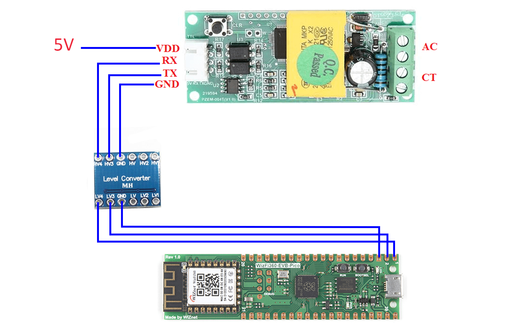
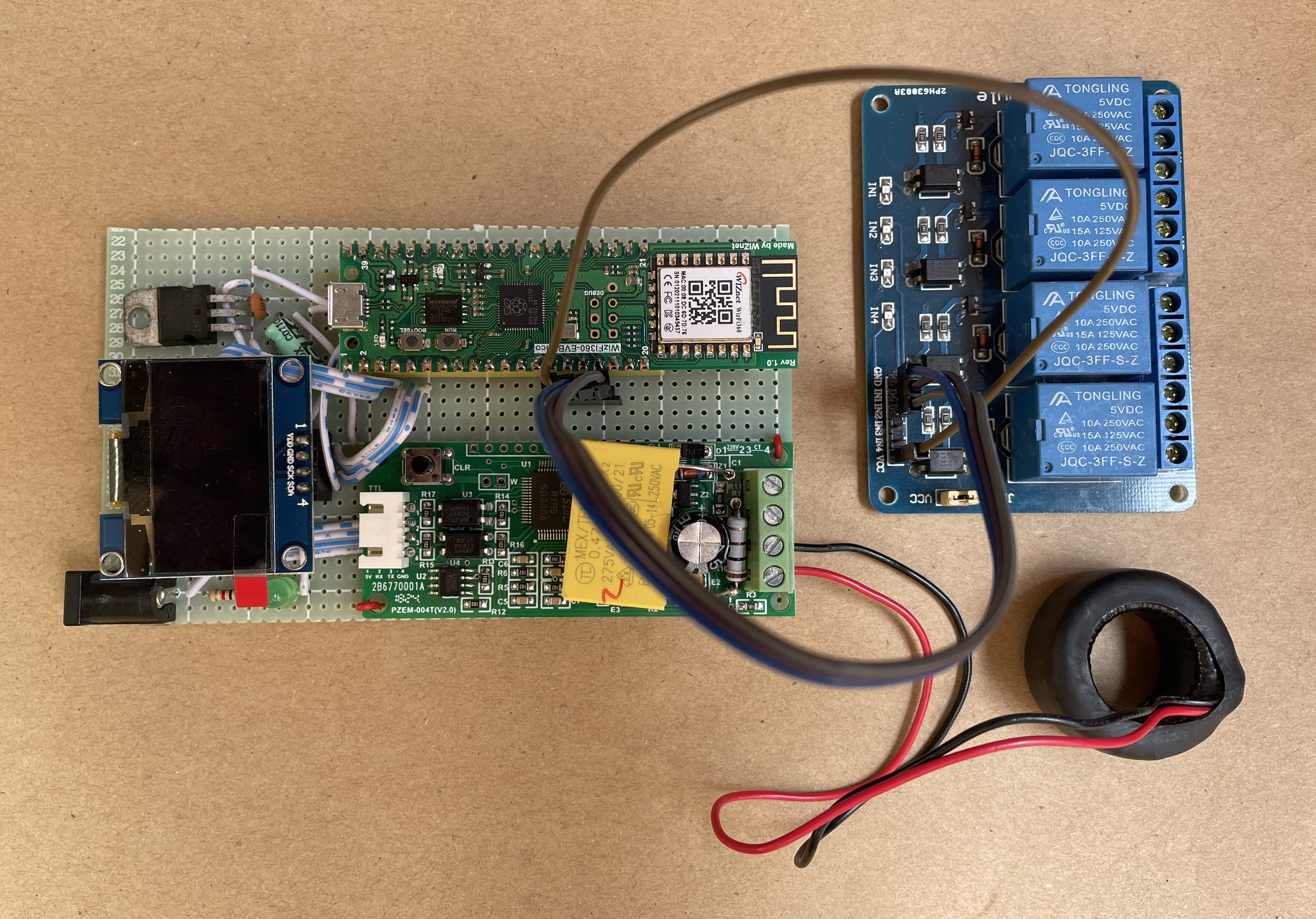
The following image shows the connection between the energy monitor module and the WizFi360 Pico.
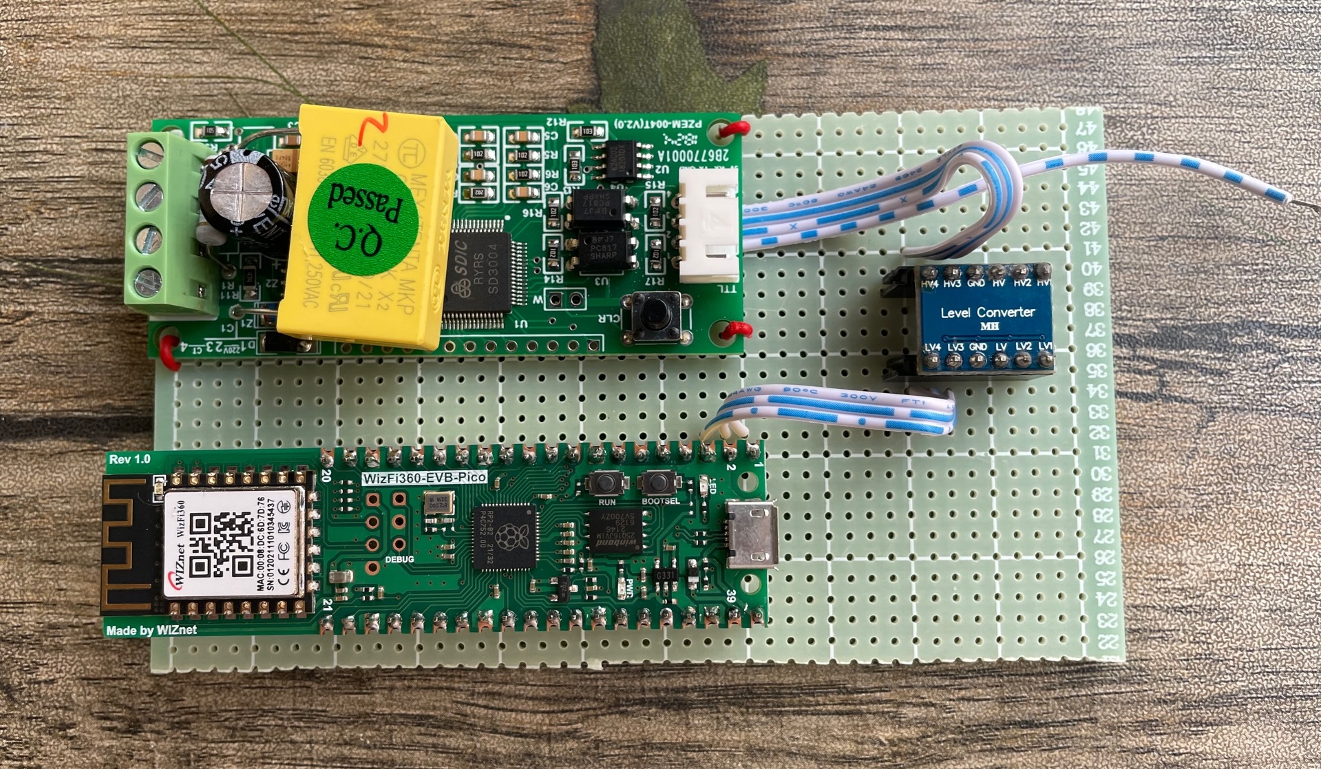
The following image shows the PCB soldering of the above connection
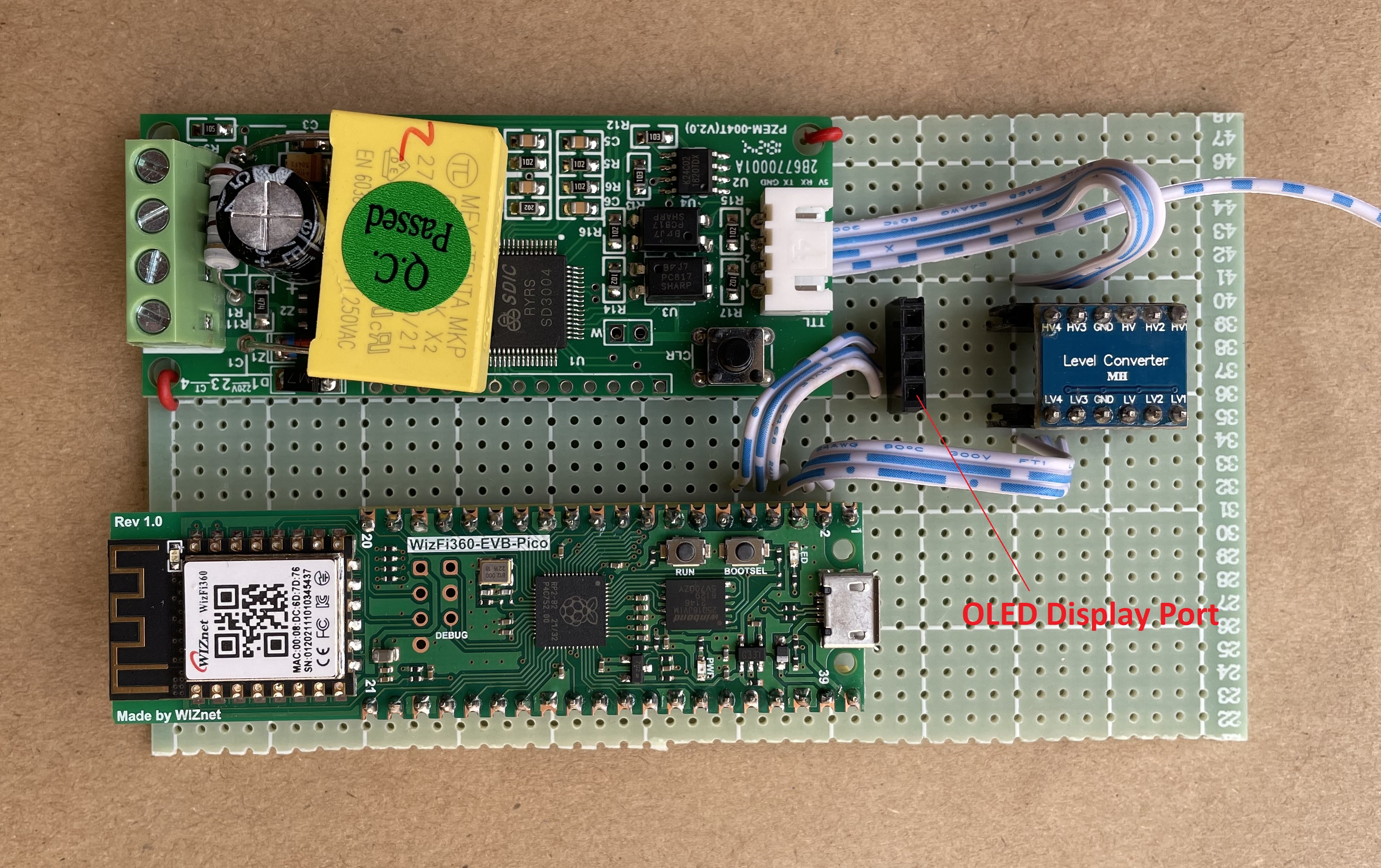
For local monitoring of the parameters, I also added an I2C OLED display to my project. For placing the OLED display I soldered a 4 pins female header to the PCB board. I used I2C1 (GPIO 4 and 5) of the WizFi360 Pico board.
For providing the power to the energy module and the WizFi360 Pico board I used a 5V linear regulator. The regulator is soldered in the breadboard with a DC barrel jack so that I can provide power to the board through a wall adapter.
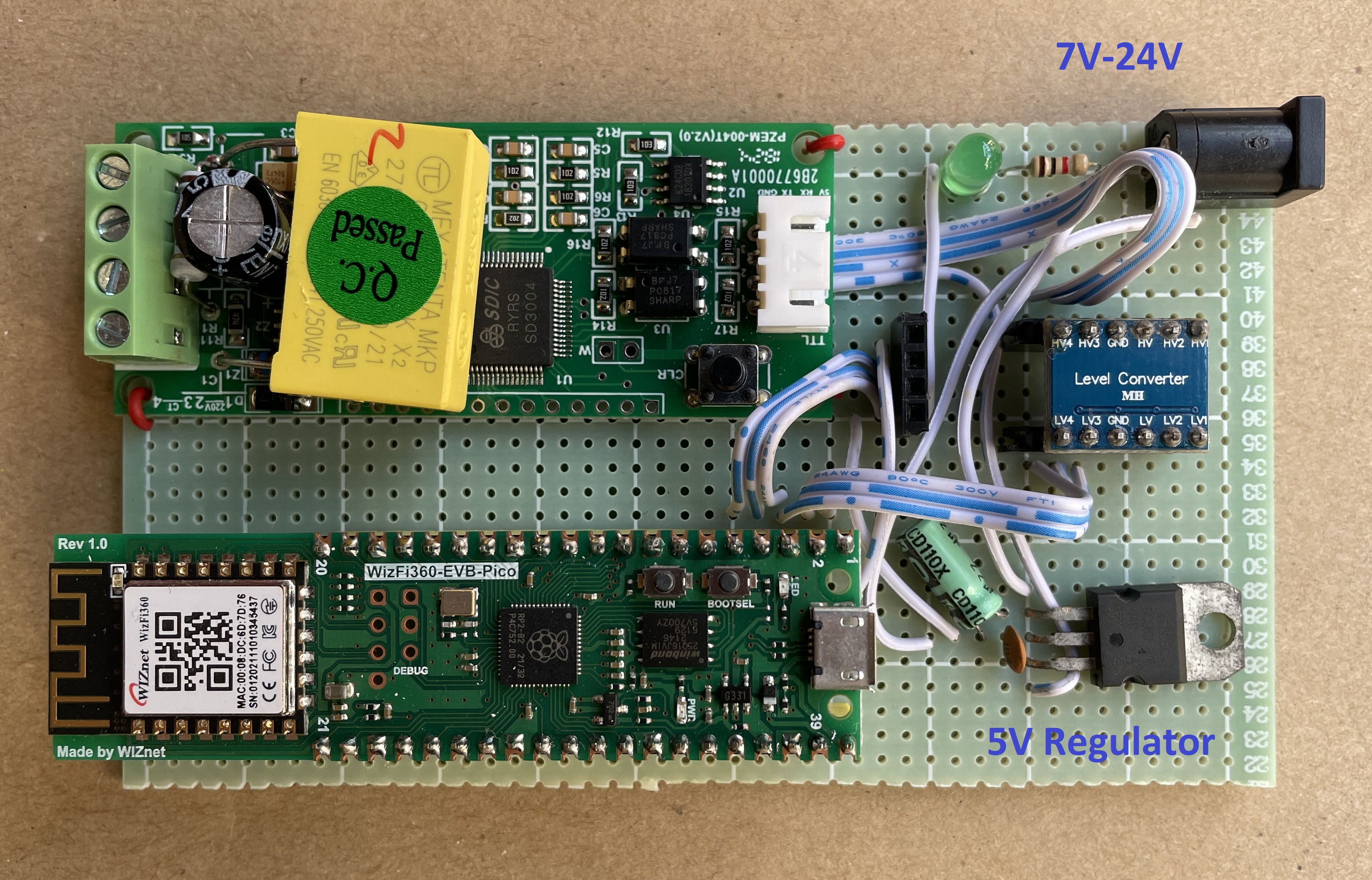
Then I connected the relay module to GPIO 12 & 13 of the WizFi360 Pico board for controlling the appliance remotely. For the demonstration, I only used two appliances but you can add more appliances according to your requirements.
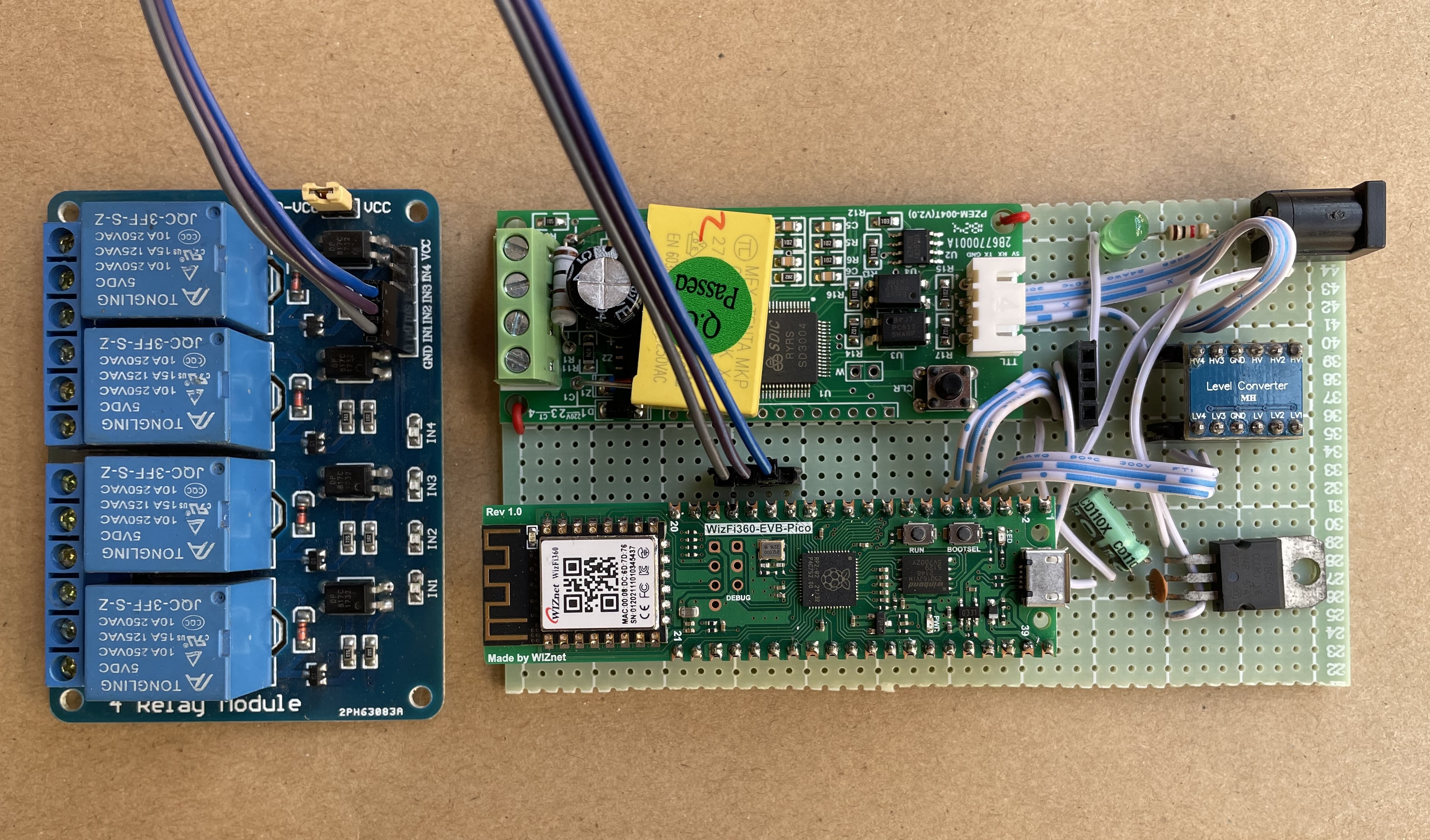
Now following the pinout of the energy monitor you need to connect the CT and the voltage supply to the energy module. For working with the energy monitor module you must provide the AC voltage to the AC Connector beside the CT connector. Otherwise, it will not work.
Schematic
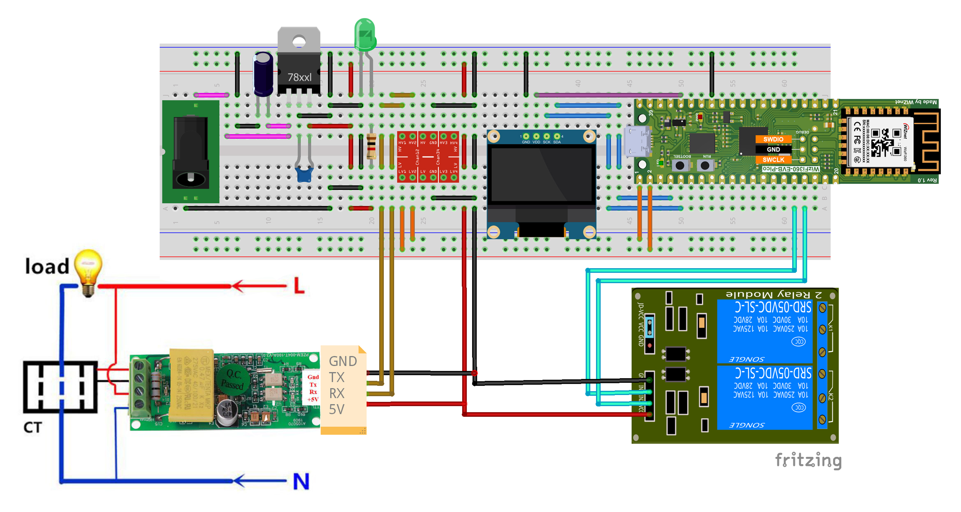
Connection
Well done! All the connections and soldering are completed. Now is the right time to write the code for the WizFi360 Pico board.
Writing Code
There are at least three ways you can write the program for the board.
- Using MicroPython
- Using Wiznet official C SDK
- Using Arduino (my favorite)
In this project, I am going to use Arduino IDE for programming the WizFi360 board. I am choosing this platform because most of the makers are used to Arduino IDE.
For building WizFi360 PICO projects with Arduino IDE, we will use the Arduino-Pico core developed by Earle F. Philhower, III. It is an RP2040 framework based on the official Pico-SDK and uses FreeRTOS for multi-thread programming. The framework is actually better than the Mbed-based RP2040 core from Arduino. To use Arduino-Pico core, you need to install the Arduino-Pico board manager, and for doing that you need to add a board index URL to the Arduino IDE’s preferences. Copy and paste the following line to the list.
https://github.com/earlephilhower/arduino-pico/releases/download/global/package_rp2040_index.jsonAfter adding this go to the Boards Manager and type pico in the search box. Install the Raspberry Pi Pico board.
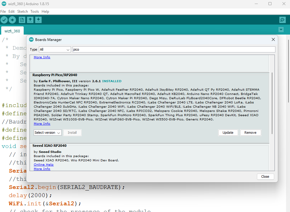
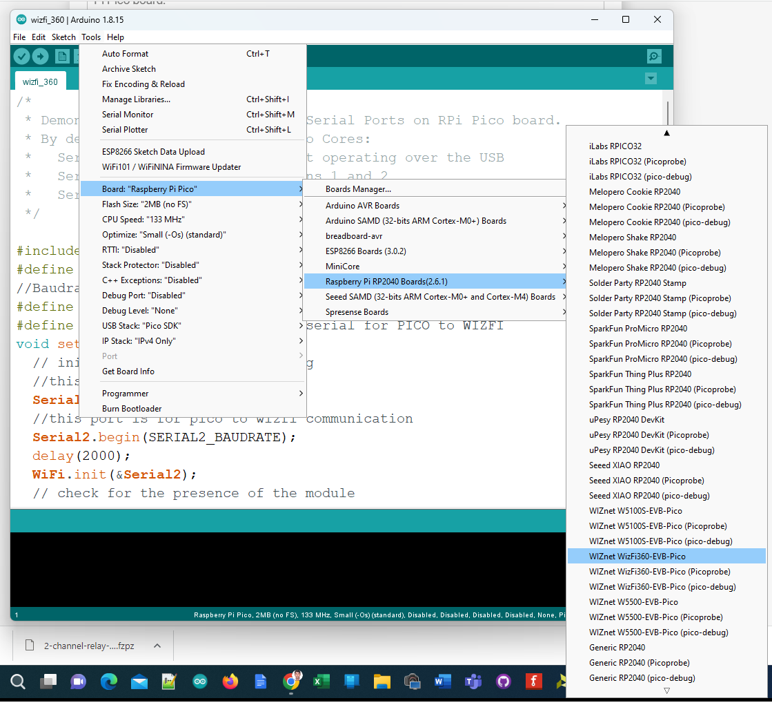
Now you can select the WIZnet WizFi360-EV-Pico board from the Tools menu. As you can see, there is a large list of supported boards. Now try opening the basic blink sketch for testing the environment setup from File → Examples → 01.Basics → Blink. Then select the port and upload the code. The LED on your board should be blinking.
Adding WizFi360 Arduino Library
WIZnet has provided an Arduino library to communicate with the WizFi360 module and a few example sketches that implement basic Wi-Fi applications. You can install the WizFi360 library by downloading it as a ZIP file and adding it to your Arduino libraries folder. Unfortunately, the library is not published yet on the official library list and therefore you can not find it on the Arduino Library Manager.
Adding OLED Library
A customize SSD1306 I2C OLED library is attached in the code section. I modified the library to work with WizFi360 Pico. Download the library and add it to your Arduino IDE.
Adding Energy Monitor Library
The PZEM-004T energy monitor library is available on GitHub. Download and add the library to Arduino from the following GitHub link:
https://github.com/mandulaj/PZEM-004T-v30If are now ready with the Arduino environment.
Configuring Ubidots Dashboard
Create an account on Ubuidots from the following link if you don't already have one.
https://industrial.ubidots.com/accounts/signup_industrial/Copy the API Token from your Ubidots and replace the TOKEN in the main code with your own token. The full source code is attached in the code section.
char ssid[] = "XXXXXXXX";
char pass[] = "XXXXXXXX";
char SERVER[] = "industrial.api.ubidots.com";
const char * TOKEN = "XXXXXXXXXXXXXXXXXX";
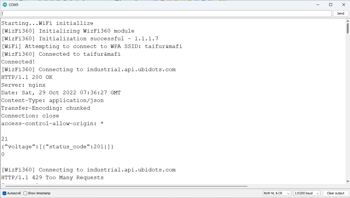
const char * DEVICE_LABEL = "XXXXXXXX"; Replace all X values with your own value and upload the code to your WizFi360-EVB-Pico board. If everything works well you will get the following output from the Arduino Serial Monitor.
Now, go to your Ubidots account and look for the device section. You will get all the parameters from the Ubidots device tab like this:
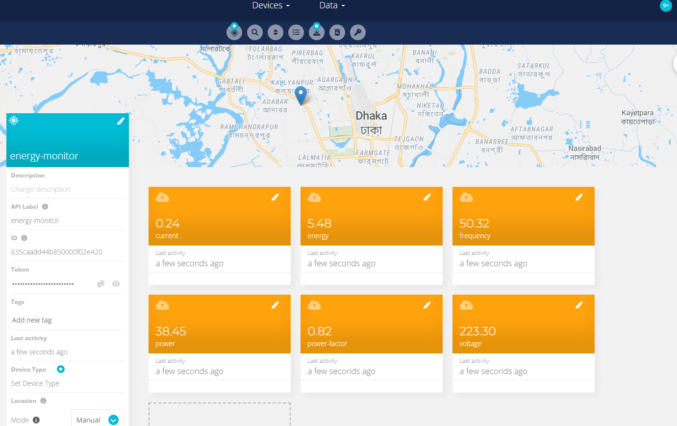
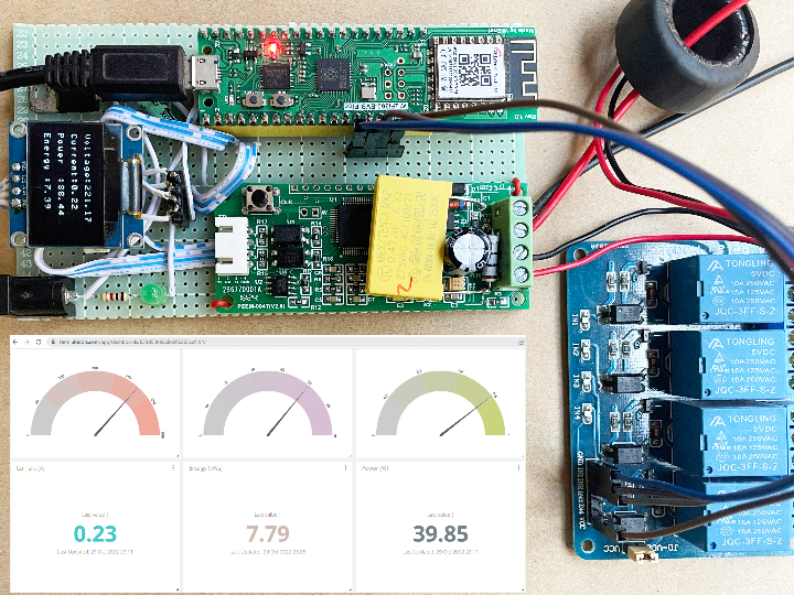
After receiving data in Ubidots you can create a dashboard from where you can visualize your all data graphically and remotely. You can also control your devices from the dashboard. The following image is the screenshot of the dashboard I have created for this project.
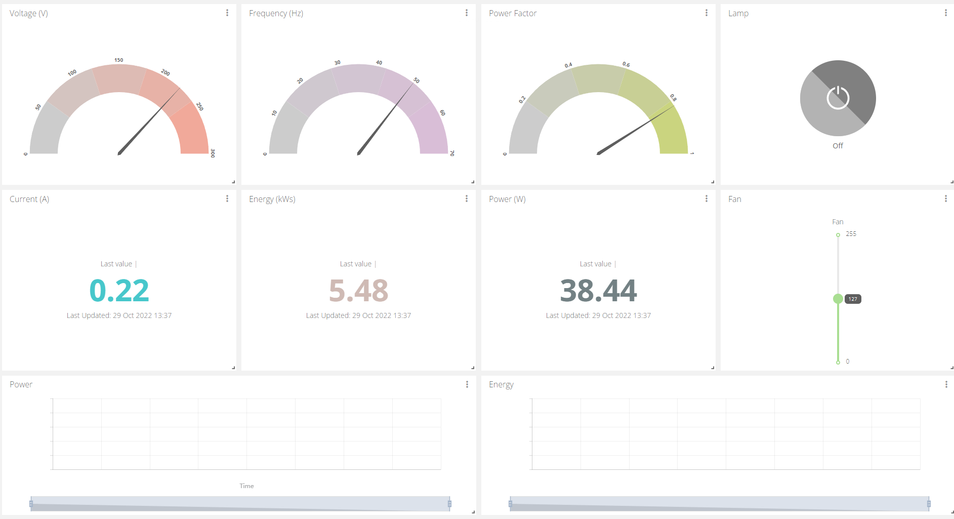
Ubidots has lots of nice widgets you can choose for your variables.
-
Full Schematic
Designed using Fritzing

-
OLED Library for WizFi360-Pico
Modified library tested for WizFi360-EVB-Pico
-
PZEM Power Meter Datasheet
-
Full Working Code
Developed in Arduino IDE