
Fish Tank / Terrarium Monitor
A WiFi / Pico equipped tank monitor. Planned monitoring includes tank temperature, water level, light level and air temperature.

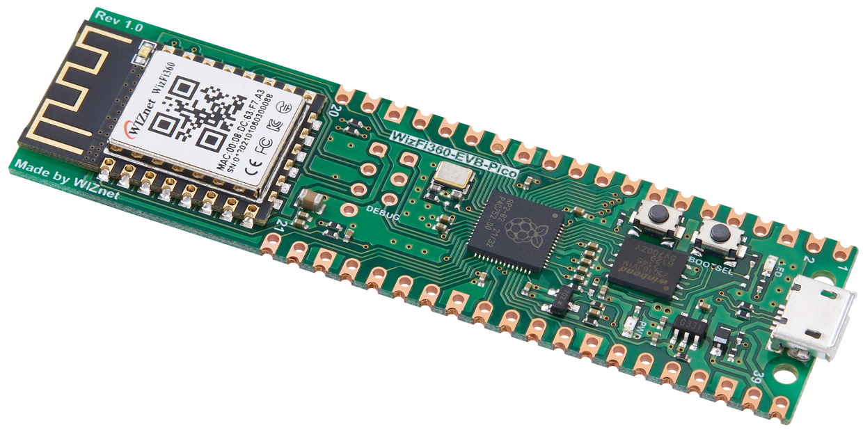
WIZnet - WizFi360-EVB-Pico
x 1
Main processor

adafruit - Adafruit Waterproof DS18B20 Digital temperature sensor
x 2
Water Temperature Sensors

Ada Fruit - Adafruit BME280 I2C
x 1
Air Temperature, Humidity

Ada Fruit - Water Detection Sensor
x 1
Leak detection

AdaFruit - Photo cell (CdS photoresistor)
x 1
Light level monitor
Aquarium Monitor (AKA AquaMon)
I have what some may consider too many aquariums. Because I enjoy data analysis and monitoring I have wanted to automate the monitoring of the environmental conditions in and around the aquariums. The sensor package I am calling AquaMon is meant to help with this project. Using the WizFi360-EVB-Pico I have been able to design a sensor package that works over WiFi to monitor the conditions within and around the tanks.
Design Considerations
There are several different conditions that I want to monitor in both my fish tanks and terrariums. I prefer to keep my data local so the WizFi360 exposes a Web Server endpoint that returns the data in JSON format. This can be processed and stored by my home servers and added to a dashboard. Future firmware versions may add more advanced reporting, http configuration and mqtt.
Any sensors that end up near the water need to be waterproof. In addition the package is kept in a plastic box with a towel for testing. The final housing will need to be water resistant, while exposing the sensors. Several waterproof or water resistant connectors are being considered for the external sensors.
Hardware and sensor selections
Here is a list of the environmental conditions that I wanted to measure, and what I picked to measure them.
- The ambient air temperature and humidity. Knowing the conditions around the tank is important. I choose the BME 280 because it works over I2C and is available and accurate. This allows allows the local air pressure to be monitored as a bonus.
- The temperature within the tank, at two different locations. This sensor has to be waterproof (aquariums are hard on things that are not). I choose that Waterproof 1-Wire DS18B20 from Adafruit. By adding two I can monitor the temperature near the heater and on the opposite side of the tank. For my aquariums this is a ceramic core heater and for terrariums this is often a heat lamp. Because of past bad experiences with One Wire interfaces on the same pin these are connected to separate pins. However, if pins are a scare resource they can share the same pin.
- The ambient and in tank light levels. I am not concerned with the absolute light levels, although this can be extracted after some calibration. So I chose to use two Photo cells on analog pins. One is pointed through the glass to monitor in tank conditions and the other is pointed at the outside environment to monitor ambient light. This allows me to adjust the light level in the tank. The Photo cell can be set in transparent silicon to protect it from water or be pointed through the glass. These can detect if the lights are on or off and even the approximate level.
- The water level within the tank. I wanted a sensor that could monitor the level without requiring electronics in the tank. I designed a custom pair of magnetic hall effect sensors. A magnet is placed within the tank on a float with the float kept within a tube. If the water level rises or falls the magnet moves up or down. When the magnetic field falls above or below one of the hall sensors they flip off, alerting me to the change. With two sensors I know what direction the water change is happening in. By configuring the sensor to require the presence of the magnet the failure state is not the default state.
- A leak sensor. This is a simple Water Detection Sensor (Adafruit 4965 but available many places). By placing this on my carpet it detects changes in conductivity when the carpet gets wet. If the voltage goes high bad things are likely happening. Due to limitations it is attached to an analog pin.
- A MicroSD card reader (optional). This allows for local storage of data and storage for more complex web pages to allow for an on device dashboard. For simplicity this is not currently included in the project but the SPI pins are reserved. This may be replaced with an integrated SPI flash chip in the future.
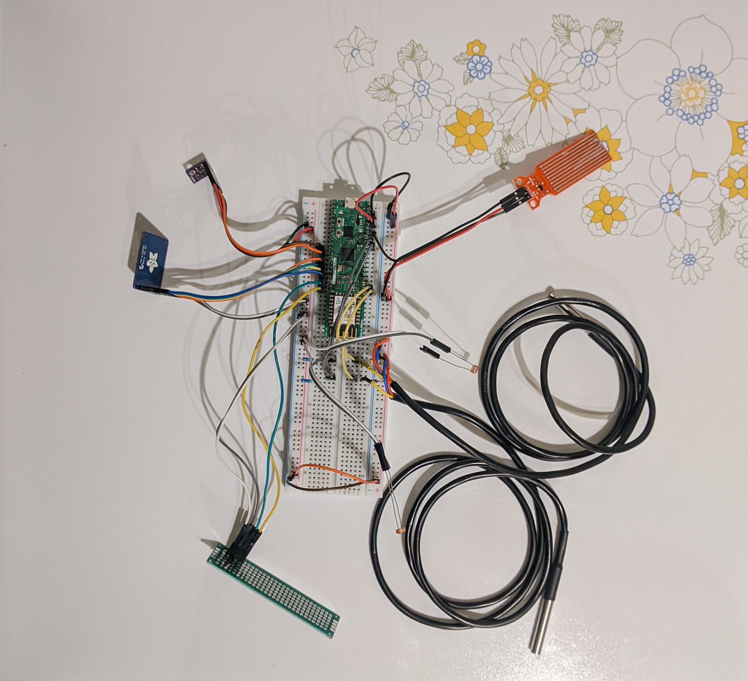
Currently when testing the AquaMon is in a plastic box, with several sensors on the outside. Once the first PCBs are available I will add a custom enclosure.
Software design
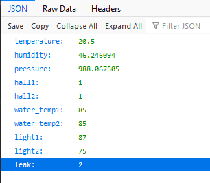
Currently the prototype is running Arduino based software. This allows for easy development as most sensors had existing libraries that worked with minimal modification. Currently the web interface is very simple. For quick testing an HTML based page is available. Alternatively, when I am caching data in a server the code can be built with #define JSON (this is the default in the .ino file) and it will return the data in JSON form. Here is a sample JSON response:
All non analog pins are defined in board.h. The arduino code supports a simple simulation mode. if //#define SIMULATION_AM is uncommented from board.h none of the sensors are required for the code to compile or the web server to run. Instead all of the sensor functions return fake data. This allows for the network code and data acquisition to be tested without any sensors attached.
All sensors have their own cpp and h file with a simple interface. This allows sensors to be quickly swapped as issues are encounter. The includes and functions are dynamically changed if the code is compiled with simulation mode on or off.
The WiFi SSID and Password is stored in the arduino_secrets.h file. Changes are not tracked in git on my development machines, greatly reducing the risk of me accidentally committing it to Github. A future update will store these in SPI flash and offer dynamic setting via serial or, hopefully, a web based page using the WizFi's AP mode for first time setup.
Because I prefer to keep my IoT data local all processing occurs on my network. The data server can poll data from the AquaMon(s) and present it in graphs or send out alerts based on anomalies. An optional Micro SD or SPI flash is wired but the current firmware does not support it do to timing issue.
Currently I am investigating the Pico C SDK with WizNet libraries. This would allow for a better integration with much more custom networking and data access functions. I would like to add webpage or serial configuration of the SSID and Password and more IoT dashboards and configuration to the device itself. This would also allow the C SDK based firmware to be MIT licensed as Arduino plus libraries almost always requires GPL.
Pinouts
The BME 280 is connected to pins 11 and 12 (GP8 and 9) these are the default I2C SDA and SCL pins which the Adafruit BME280 library requires.
The Hall Sensors are attached to pins 19 and 20 (GP14 and 15). The DRV5021s are on a custom protoboard with .1 uf caps. The RP2040s internal pullups are used. The pins go to ground when the magnet is near. Because the designed alert state is magnet missing when the float rises or falls the system also alerts if the sensor fails.
The Water Temperature probes are on pins 21 and 22 (GP16 and 17). They are pulled up with a 4.7k resistor.
The Light Sensors are on pins 31 and 32 (GP26 and 27, ADC 0 and 1). They are pulled down with a 10k resistor.
The Leak Detector is on pin 34 (GP28, ADC 2).
Pins 14-17 (GP 10-13) are reserved and are optionally used to connect to either SPI Flash or a Micro SD card reader. These are hardware SPI1 and each is connected to the appropriate function.
All sensors are 3.3 volt. Power is provided from the 3v3 pin (36). Total power consumption was monitored under load to ensure that the regulator was not being overly taxed.
Project Page
The source code, BOM and other data is being uploaded to my GitHub. This is found here: https://github.com/DanielVanNoord/AquariumMonitor. As the project progresses circuit design and case design files will be added, as well as my notes and comments on changes.
-
Arduino Source
Arduino testing source, also supports simulator mode


-
Prototype BOM
The basic parts (or equivalents) of the prototype, buildable on breadboard.