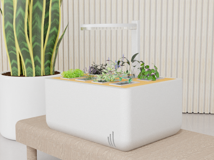
Ivypots is a solution for peoples who want to grow indoors vegetables, without worrying about How Often & How Much Watering Houseplants.
COMPONENTSHardware components
dfrobot - Gravity: Analog Capacitive Soil Moisture Sensor- Corrosion Resistant
x 5
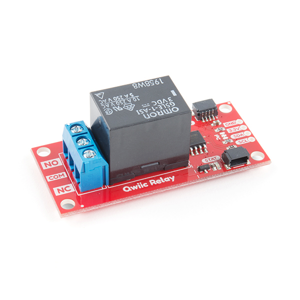
sparkfun - SparkFun Qwiic Single Relay
x 1
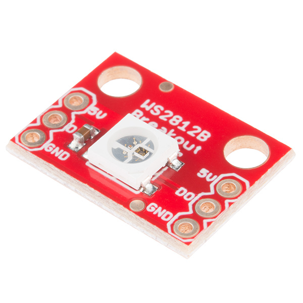
sparkfun - SparkFun RGB LED Breakout - WS2812B
x 1
This is for the boot of the device
adafruit - USB Li Ion Battery Charger
x 1
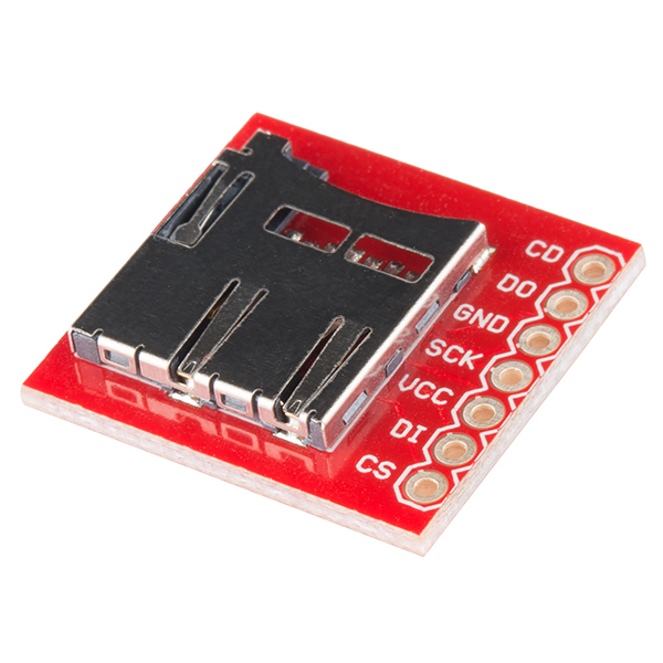
sparkfun - SparkFun microSD Transflash Breakout
x 1
For the Data logger and the firmware
Wurth electronic - WL-SMDC SMT Mono-color Ceramic LED Water clear
x 8
This is for the Horiculture
texasinstruments - 555 Timers Ultra Low Voltage
x 1
This is for the mist generator
adafruit - Adafruit Waterproof DS18B20 Digital temperature sensor
x 2
this is for the temperature of the peltier
Software Apps and online services
Arduino - Arduino IDE
x 1
blynk - Blynk
x 1
Arduino - Arduino IoT Cloud
x 1
PROJECT DESCRIPTION
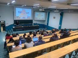
The IUT Lyon1 is an educational institution in Lyon, France, specializing in technological and vocational training. It plays a significant role in fostering innovation for ecology. Through programs, research, and collaborations, it equips students with skills and knowledge to address environmental challenges and promotes sustainable practices.
Here is where I want to install my project. This project is meant to Help our Canteen to produce lettuce and other stuff.
Introduction :
Ivypots is a solution for people who want to grow indoors vegetables, without worrying about How Often & How Much Watering the Houseplants are.
Ivypots uses the Peltier Effect to generate water from the humidity to finally be able to water the plants. Thanks to the SD Card we can use the results to create a graph in Excel to analyze the plants to determine how much and how often the plants need to be watered to give the best possible experience.
Water Generator :
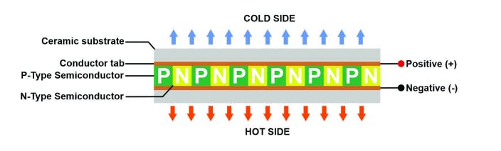
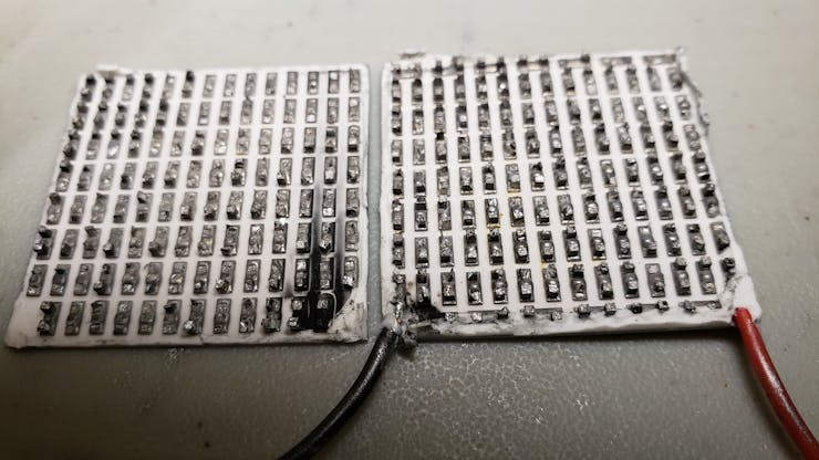
To be able to produce water, you must already understand what a Peltier module is. The module Peltier is a component that can perform heat exchange without any moving parts. It is a semiconductor cooler which consists of a collection of legs composed of P or N-type semiconductor material.
A leg is constructed by creating several layers of substrate material, built up in order to have some height.
Thermoelectric coolers operate according to the Peltier effect. The effect creates a temperature difference by transferring heat between two electrical junctions.
When the current flows through the junctions of the two conductors, heat is removed at one junction and cooling occurs.
Depending on the direction of the current, when current is applied one side gets hot and the other gets cold. Thanks to this physical effect would be able in theory to produce water thanks to the condensation.
Note that, this is the same process as the so-called Dehumidifier. (or atmospheric water generator)
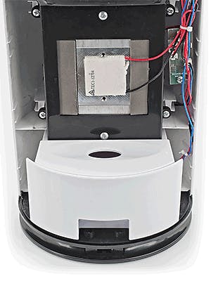
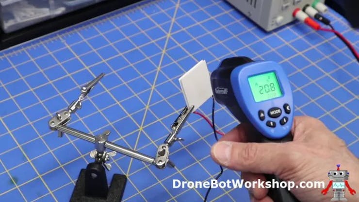
The system is composed of three parts: the Peltier module, a HeatSink and a fan with these components the Dehumidifier can produce water.
For the device to be most effective a heat sink has to be mounted on the hot side for heat transfer, otherwise, the cooling effect will be minimized and it will not give proper results.
Source: Peltier condensation Dehumidifiers By Trotec
How to control it ?
To be able to control the peltier, we have to remember that this components is made out of a collection of legs composed of P or N-type semiconductor material. Knowing that we can use the peltier with "PWM" just like a Transistor or a Mosfet for example.
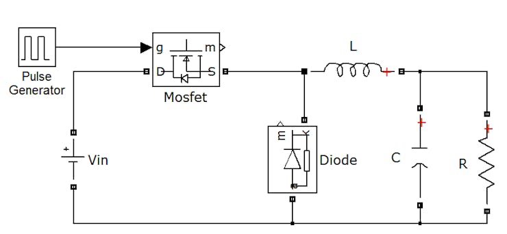
For this circuit we will be using what we call a Buck Converter wich is this :
The resistor will be our Peltier Module and for the Mosfet we will put the PWM signal in it in order to regulate the peltier module properly.
Here is a demonstration of the water generator :
Light detection works :
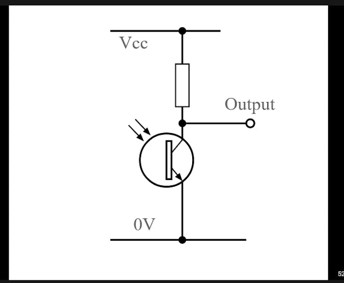
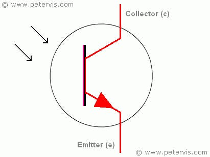
For the light detection, we can use the Phototransistor sensor present on the multisensor module environement kit of DFrobot because of its high accuracy
So how does it work?
The multisensor module consists of a phototransistor and a 10kΩ resistor. These two components create a voltage divider, as shown on the following image:
The base of the phototransistor let the voltage pass in the presence of light and block the voltage in the absence of it.
To understand a little better how it works, Here is an example:
As you can see, the output may varies proportionally to the light level falling on the base junction. The range of light variation it detects depends upon the value of the load resistor.
Now that we know this, we could use this mechanism to deploy LEDs to give light to plants.
How can we reproduce the sunlight?
You may know that plants need light to be able to photosynthesize, but how can we do this?
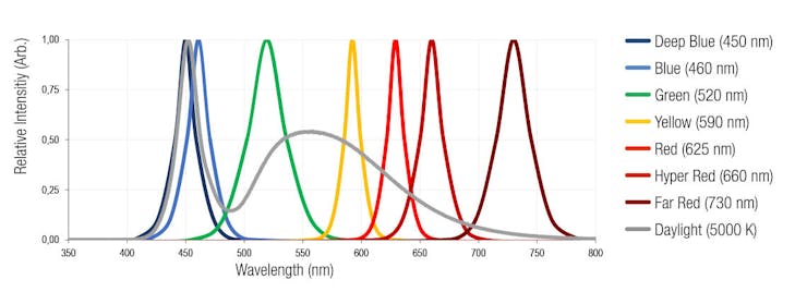
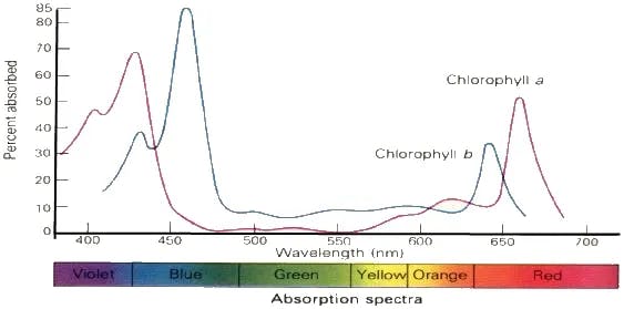
First of all, plants need a certain spectrum of light especially ultraviolet radiation between 260–380 nm (UV), photosynthetically active radiation between 400-700nm (PAR), and infrared radiation (Far-Red) between 700–850 nm.
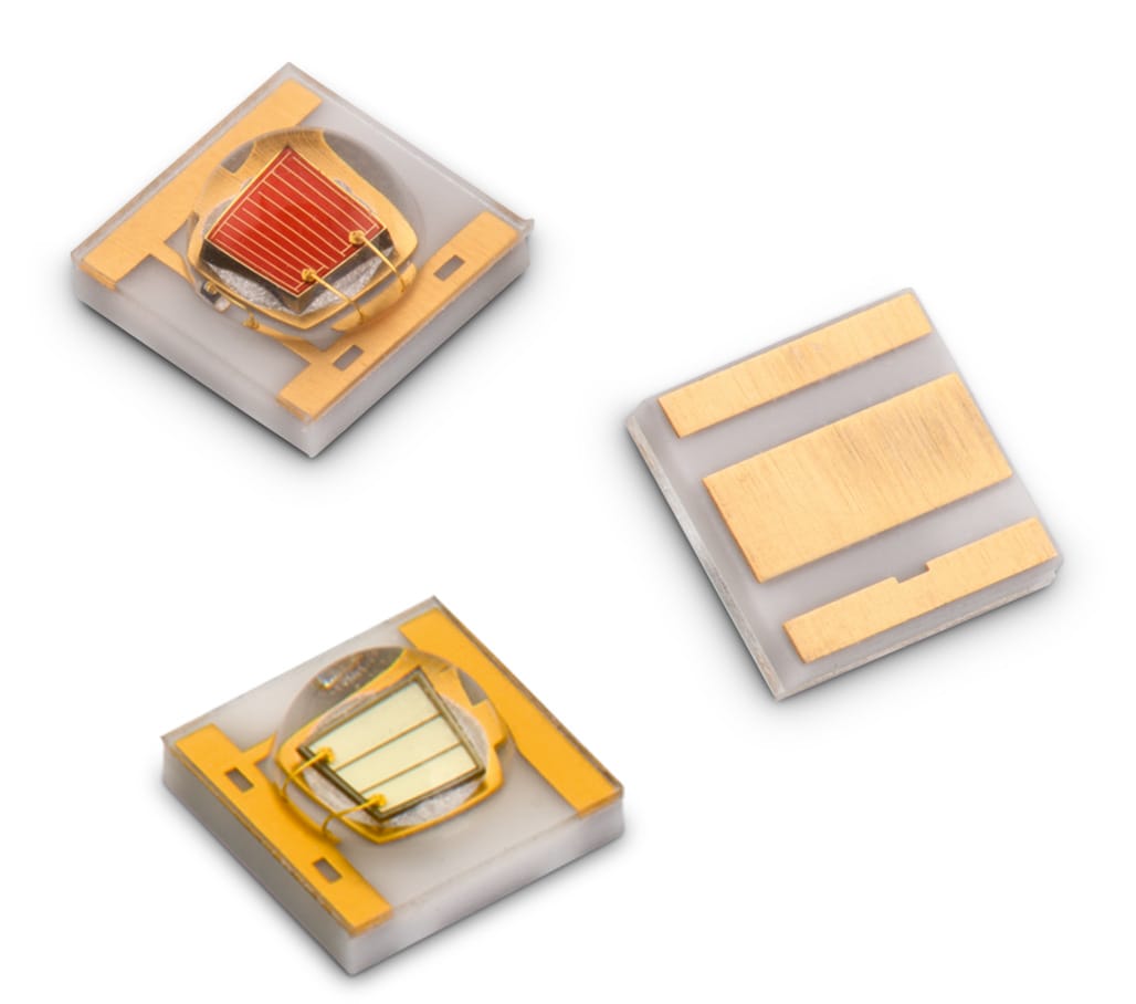
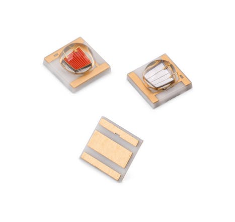
So knowing this we can use a certain type of led like the WL-SMDC Horticulture LEDs from Würth Elektronik :
Why I decided to choose 6 Hyper-Red LEDs, 4 Far-red LEDs, 2 Deep-Blue LEDs, and 4 White LEDs.Why these LEDs?
Because of their light spectrum which matches the light spectrum of plants, which is the PAR Spectrum. (that includes Chlorophyll B (400-470nm), and Chlorophyll A (640-670nm) ).
Tank level indicator :
Why we need this? Well sometimes we don't know if our Tank will be sufficient for our plants and we also don't know if the water generator will generate enough water to the tank, thats why we need a water level indicator:
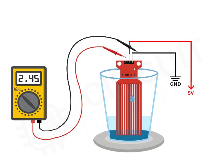
There are many way to know if a tank is full or not, one of them is to use a "Resistive Water Level Sensor"like this one :
As you can see the PCB of this sensor is made out of long conductive plates. When the water reaches a certain level, the conductivity between the two plates changes, and by measuring the changes, we can determine the water level.
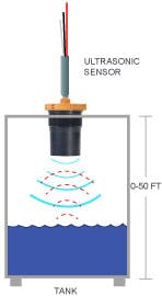
But there is one downside to this. It's the fact that the conductive plates can pollute water while rusting, and it is a pretty big issue since we want our plant to be healthy. So, to be able to mesure water without killing our plant we can use an ultrasonic sensor as shown below:
Our ultrasonic sensor will be waterproof, so we can be sure that there will be no problem damaging the sensor. So how does this work ? Like I said previously, this sensor uses ultrasonic impulsions to detect a distance between it and another object, at a certain frequency.
Battery Management :
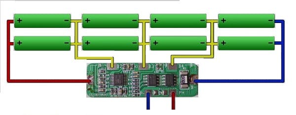
Most of the components on our system consume a lot of energy and we want to have a system that can work off grid. To be sure that our smart pot has a long battery autonomy, we have to designe our own custom battery :
To do that we need first to understand how a BMS works and we also need to know the technical characteristics:
What is a BMS ?
A BMS (Battery Management System) is a system that monitors, controls, and protects rechargeable batteries, ensuring optimal performance, longevity, and safety. It manages functions like monitoring battery parameters, balancing cell voltages, providing protection against overcharging and over-discharging, estimating battery state of charge and health. In some cases it can enabled communication with external devices or systems.
For the battery there are many types and models. The most known are the 18650 and the 21700. In my case, I went with Samsung 18650 wich is a chip and pretty fast to operate.
When you have to design a battery pack, you have to choose the battery in term of the system requirements. In our project we have the power part that consumes about 15V max and 3 A max, wich is a lot. In order to have enough energy to keep our system last for about 4 hours, we have to use a battery with the samsung ICR18650 wich have max volatge (VCell) of 3.6 V Max and a max current (Icell) of 5 A and a Capacity max of 2.5 Ah.
Now we know the the technical characteristic of our battery cell, know we can make a battery pack by putting 4 cells in series with a another 4 cells but in parallel. That's leave one choice for our BMS , A BMS 4S2P ( 4 series 2 parallel) like this one :
Great job ! Now you know how to make a battery pack.
Soil Moisture Sensor :
To be able to know when we have to give plants water, we have to use what is know as a soil moisture sensor.
A soil moisture sensor is a device that measures the moisture present in the soil, helping optimize irrigation and plant growth. It consists of a probe inserted into the soil and a control unit that displays or transmits moisture readings. It helps avoid overwatering, underwatering, and water stress in plants.
Here is an exemple of a Soil Moisture Sensor :
There are many types of soil moisture sensors. This one is a "Resistive" soil moisture sensor
How does it work ?
A resistance soil moisture sensor works by measuring the change in electrical resistance between metal electrodes inserted into the soil. The resistance decreases as the soil becomes wetter, allowing the sensor to estimate the moisture content. Calibration is needed in order to provide accurate readings.
The downside is that the resistive type of soil moisture sensor are made out of long conductive plates wich, like the water level sensor, is not good for the plants' health, especially for the potting soil wich will be pollued.
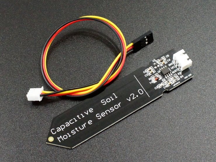
Instead of using those type of Sensor, I went with the Capacitive Version wich is a more durable and more precise sensor than the other type.
Here is what is looks like :
But how does the capacitive work ?
A capacitive soil moisture sensor measures changes in electrical capacitance between two electrodes placed in the soil. The capacitance increases as the soil becomes wetter, allowing the sensor to estimate the moisture content. Calibration is necessary for accurate readings.
And it is better than the other's options because, a capacitive soil moisture sensor is often preferred due to its accuracy, sensitivity to small moisture changes, corrosion resistance, longer lifespan, and less susceptibility to environmental factors.
Thanks to that, will be able to Mesure the soil moisture for our plants with accuracy and ease.
Mist Generator :
When it will be to hot in summer, we will need to help our plants to cool down, by for exemple using the Mist Generator.
A mist generator is a device that produces a fine mist by breaking down a liquid into tiny droplets. It is used for purposes such as humidification, cooling, and special effects. The generated mist can have applications in increasing humidity, cooling environments, and suppressing dust. You can find a mist generator in a for exemple in a home humidificator.
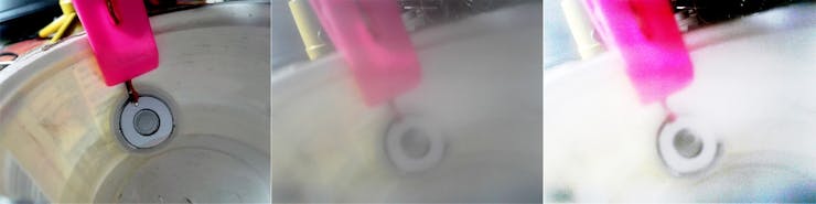
It exist differents type of mist generator, our will be the piezo version which utilizes the piezoelectric effect to produce a fine mist. It consists of a piezoelectric element, typically made of ceramic or crystal material, that vibrates when an electric current is applied to it. This vibration causes the liquid, usually water, to be atomized into tiny droplets.
Here is an exemple :
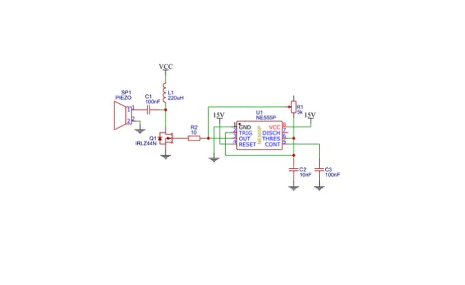
Thanks to the schematic that was made by GreatScott , we will be able to create our own mist generator, using a 555 timer wich is an IC that can create a certain frequency by adjusting the differents passive components. by adjusting the frequency we can meke our mist generator less or more powerfull.
Of course you can buy a pre-made one, but I think it's also great to know how the differents components are able to work together.
Now thanks to this circuit we will be able to create mist for our plants and protect them from the high temperature!
Breakdown detection :
Imagine that you receive a device, you have used your device for the first time but you encounter a breakdown at the start, you don't where to begin the investigation and you start feeling angry because you didn't find the problem and you finnish by giving up.
Well,
Here is a solution for this a breakdown dectector that let you know wich component are faulty.
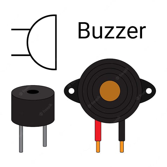
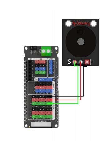
How we do that, by just using one component the buzzer.
Before doing anything else, we need to understand how does work a buzzer, you probably hear that before are even see it before like in this meme, when you have two choice but you don't know wich one to choose and you start panicking :
A buzzer is an electronic component that produces a buzzing or beeping sound as a signal. It typically consists of a small sound-emitting element, such as a piezoelectric transducer or an electromagnet, which is adjusting a frequency.
Those frequency can be used like in music when you have to create a special sound.
Here is the symbole of Piezo Buzzer :
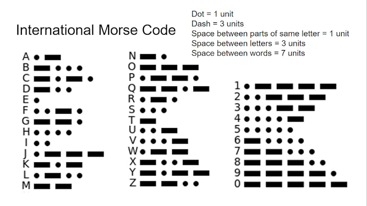
In our case we will make a morse code, that works with two things a "Dash" and a "Dot" those two sound are really useful because we can use them for creating letters but in morse code:
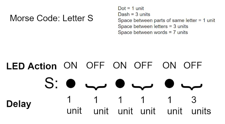
In this Screenshot you have all the alphabetic letters but in morse code, when you use a dash it's generate a "long" sound but when you use the DOT it generate a "short" sound, by adjusting those two thing you can make any letter like a "S" or a "O".
if you want to create a sentence you also have to use a spacer, it's just a void that leaves time to the person who heard the sound to understand what the sentance mean.
Here is example of a sentence created by a morse code using arduino :
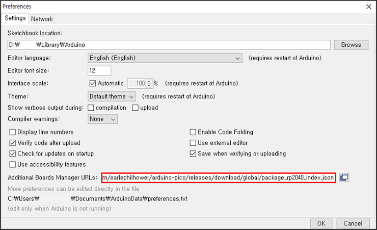
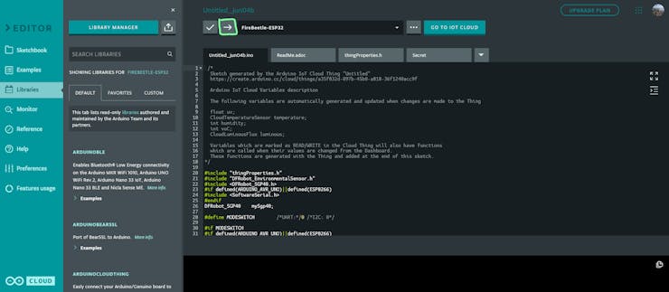
Additionally, if you are using the Firebeetle esp32-E, minor settings are required in the Arduino IDE.
The new ESP32-E FireBeetle supports WiFi and Bluetooth dual-mode communication, has ultra low power consumption and even includes an on-board charging circuit so you can power it with a lipo battery (and charge it over USB-C).
① Run the Arduino IDE
② Open Preferences
You can open it through 'File → Preferences' in the menu bar of Arduino IDE.
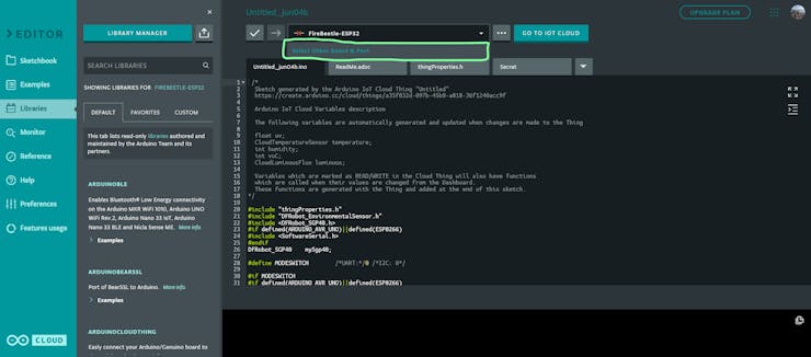
Import those library into the Arduino online IDE like this :
open the Ivypots zip file that can be found in my github page Ivypots.ino and open it.
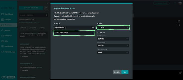
Then select the firebeetle esp32-E board and transfer the code into it :
Arduino Code :
Go to my github page and download the zip file
* This zip file contains all the elements that you need in order to build this project.
Once that is done, open the zip file, search for Ivypots.ino and open it.
Finally, transfer the program to the Firebeetle esp32-E.🥸
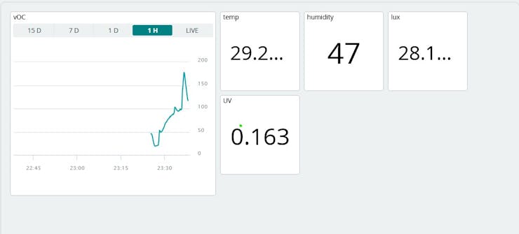
If the program works you should have this on the blynk app : 😎
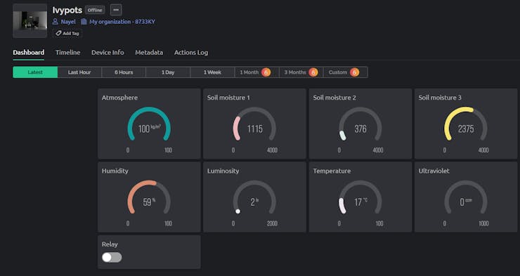
Or if you using Arduino Cloud platform you should at least have this :
It can only show the mesurements of the Multifonctional and the VOC sensor because there is a limitations with the number of components that we can see. But here another example a Dashboard that include Soil Moisture sensor Pump and peltier fan speed, peltier temp and tank level indicator :
Here is an example of what you can do with the SD card using the excel :
Conclusion + Improvements :
First of all I'd like to thanks DFrobot and Hackster for providing me the Environmental Sensing kit, without this pack I don't think it would be possible to continue this project. For the Results that we need to see on arduino Cloud, I think for a big project like this, it is better to pay the subscriptions to have the full access of arduino cloud, Using arduino cloud have a good potential to make thing more clear and more simpler.
Now in terms, of improvements:
I think creating a finished product would be really cool because I have created some part and finish them by doing a PCB like the mist generator, but those part a really tiny. I think the most important part of this project is the horiculture LED driver that I need to make as a PCB .
Next, would be to create an app with Flutter that can be compatible with all the platform like IOS or Android.
Finally, to be able to call my project a smart pot off-grid, it would be necessary to add a solar panel that can recharge the smart pot's battery.
Documents
555 timer Great Scott
By using his schematic, I was able to generate mist for the differents plants
Horiculture LightGreat Scott
By using his schematic, I was able to generate enough light for the differents plants
Horiculture LightGreat Scott
By using his schematic, I was able to generate enough light for the differents plants
Peltier schematic example
This only an example of a buck for the peltier control, this is not the finished one, I'm using this only to demonstrate the concept
Schematics part 1
This is the schematic with the Pump, the Soil moisture sensor, the VOc sensor and the multifunctionnal sensor.
Buzzer schematics
This is the schematics for the Buzzer signal, that signal with a sound when there is a problem in the system