



wled custom builds
WLED modifications for sp530e hardware Controllers with ESP32-C3 chips
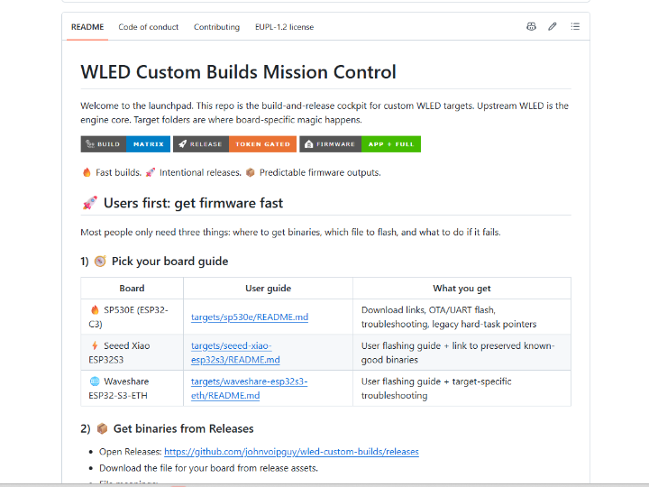
WLED Custom Builds — W5500 Ethernet for LED Controllers: A Field Study in TOE vs. MACRAW
#W5500 #WIZnet #TOE #MACRAW #ESP32S3 #WLED #OTA #DDP #E131 #ArtNet #PoE #SPI
📚 Context: Independent open-source maintainer project — a build-and-release pipeline for custom WLED firmware targets, with the Waveshare ESP32-S3-ETH (W5500) as its most technically documented line. ✅ Verification status: Hardware-validated on two physical Waveshare ESP32-S3-ETH boards. Ethernet/PoE link-up, Wi-Fi, DDP over both transports, the web UI over both transports, and runtime LED bus reconfiguration are all confirmed passing on the recommended v17 line. MQTT is explicitly listed as not yet tested, and OTA — while described by the maintainer as working automatically over Ethernet — is not itemized in that validation list. The superseded v16 line is documented with an equally rigorous negative result.
01 — What is this project?
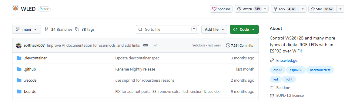
🔷 First, some background: what WLED is, and why it works differently from ordinary firmware
Most embedded firmware is written for one product. You define the behavior, compile it, flash it, and that binary belongs to that device. WLED does not work that way, and understanding why is the key to understanding this repository.
WLED is an open-source firmware for controlling addressable LED strips — WS2812-family strips where every individual pixel has its own color, as opposed to a normal LED strip where the whole run is one color. You flash WLED onto an ESP32, connect a strip to a data pin, and the board joins your network and serves a web interface.
The crucial part: the behavior is not compiled in. WLED ships with a large built-in library of lighting effects — rainbow sweeps, fire flicker, music-reactive patterns, solid colors — and the user picks them from the web UI at runtime. Even the hardware wiring is configured through that same web UI: which GPIO carries the LED data, how many pixels are on it, which chipset they are. Those values are stored as JSON in flash and read at boot.
This means one binary serves an unlimited number of different wiring setups. The only thing that genuinely requires a different binary is a different MCU family — an ESP32, an ESP32-S3, and an ESP32-C3 produce incompatible machine code — which is why WLED's official releases are published per-MCU rather than per-board. A user downloads the one matching their chip and configures the rest by clicking.
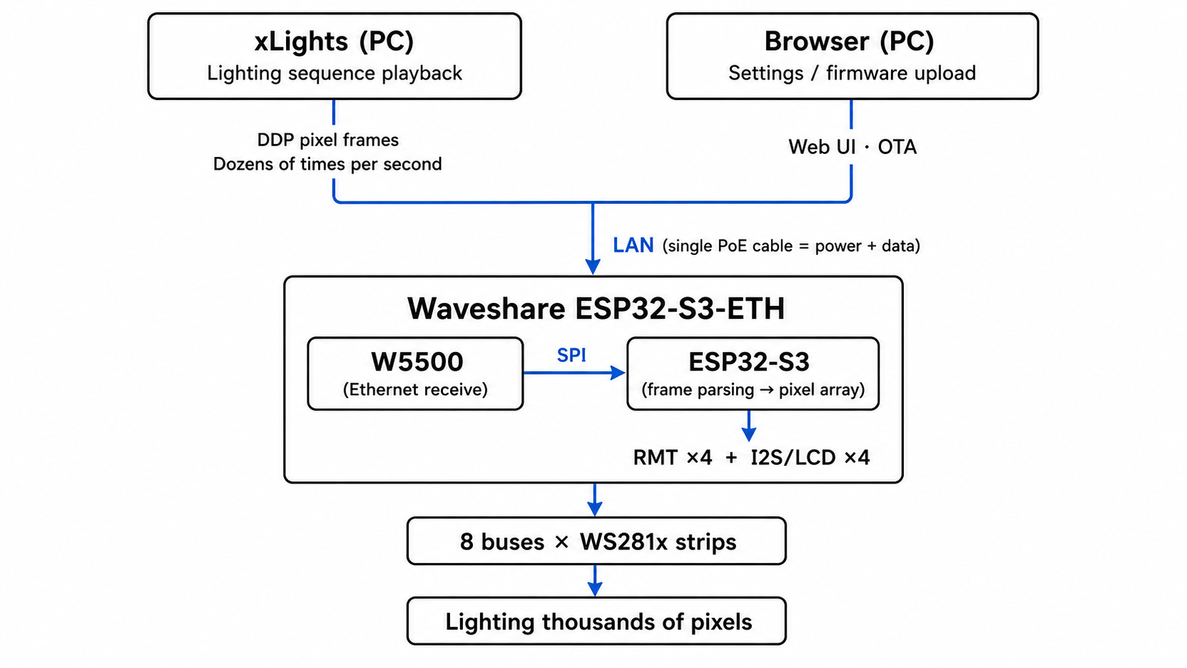
For large installations, WLED also accepts live pixel data from professional lighting software over the network, using the protocols that industry already runs on: DDP, E1.31 (sACN), and Art-Net. A PC running sequencing software such as xLights streams frames continuously, and the controller becomes a rendering endpoint rather than an autonomous device.
🔷 Where that model breaks — and why this repository exists
The web UI can only expose features that exist in the compiled binary. If the code for something isn't there, no amount of configuration will summon it.
The Waveshare ESP32-S3-ETH board carries a WIZnet W5500 Ethernet controller on SPI. WLED's upstream Ethernet support was built exclusively around RMII PHYs attached to the ESP32's internal EMAC — a peripheral the ESP32-S3 does not physically contain. On an S3, WLED's stock Ethernet board table doesn't merely fail to list this board; the build refuses to compile at all.
wled-custom-builds exists to close exactly that kind of gap. Concretely, it does three things:
① It carries board-specific source modifications, not configuration presets. Each supported board has a folder containing .patch files that surgically modify upstream WLED source — network.cpp and others — plus vendored copies of libraries the maintainer had to fix, a custom partition table .csv, and PlatformIO environment fragments defining pin assignments and flash behavior. The W5500 Ethernet support is newly written driver integration code, not a flag being switched on. Upstream WLED is refetched clean on every build and the overlay is applied on top, so the engine core stays current while the board work stays separate.
This board actually carries three build lines: v15 (WLED 0.15.x, preserved and frozen, no longer actively developed), v16 (WLED 16.0.1, W5500 hardware-socket Ethernet), and v17 (WLED main, native lwIP W5500 — the recommended line). This curation concerns v16 and v17, where the Ethernet architecture work lives.
② It builds those targets and publishes finished binaries. GitHub Actions builds on pushes and PRs that touch targets/** or the workflow file itself — deliberately narrow triggers — and writes a dated log and build-metadata JSON for each run, and publishes to GitHub Releases — but only when the push commit message contains the token release; adding legacy marks it as a prerelease rather than latest. Most WLED users have no development environment and cannot build from source, so shipping ready-to-flash binaries is the entire point of the distribution side.
③ It splits every release into two artifacts, specifically to make firmware updates survivable. This is the part that dominates the repository's own documentation, and it deserves an unambiguous explanation.
🔷 About OTA: what WLED already provides, and what this repository actually built
OTA (Over-The-Air update) is a stock WLED feature. This repository did not create it. In WLED, OTA works like this: you open the board's web UI, go to Settings → Security & Updates, and upload a firmware file from your PC. The board writes it into its spare application partition and reboots into the new image.
Why that matters so much here: these controllers get installed permanently — twelve meters up a façade, inside a stage rig, behind a wall. Once commissioned, reaching one with a USB cable means a ladder and a service call. OTA is the difference between a five-minute update from a laptop and a site visit.
What this repository built around that feature is twofold.
First, the two-artifact release format. Every release publishes:
| Artifact | Delivery method | When to use it |
|---|---|---|
wled-<version>-<target>-<suffix>.app.bin | OTA — uploaded via the board's web UI | Updating a board that is currently running and reachable |
wled-<version>-<target>-<suffix>.full.bin | USB/UART — flashed with esptool | New board, unresponsive board, or after a partition layout change |
The .full.bin merges bootloader, partition table, and application into a single image — the bootloader is the small program that runs first and decides which application partition to boot; the partition table is the map telling it where everything lives. The build step that produces it fails loudly if any of the three inputs is missing, because a half-formed recovery image on a release page is worse than no image at all.
This split exists because OTA has failure modes with no software escape. A build whose partition layout differs from what's on the device cannot be delivered as an .app.bin. And a mismatched flash-mode header boot-loops inside ROM before any application code executes, producing no serial output whatsoever — recoverable only by erasing the chip over USB. The documented rule is one sentence: if OTA is rejected or the board won't boot afterward, flash the matching .full.bin over UART.
Second — and this is the part that makes the whole project a WIZnet story — the maintainer discovered that whether OTA can travel over Ethernet at all depends entirely on how the W5500 is integrated. Two build lines were produced for the same board. On one, OTA reaches the device only over Wi-Fi even though the Ethernet port has a working IP address. On the other, OTA arrives over Ethernet with no additional code. For a PoE-powered controller on a site with no usable Wi-Fi, that distinction decides whether the installation is remotely maintainable or not. Sections 03 and 04 explain the mechanism in full.
02 — Why Ethernet for LED control?
🔷 Realtime pixel protocols are unforgiving
DDP and E1.31 are UDP streams with no retransmission and hard deadlines. A frame that arrives late is worse than useless — the renderer has already moved on. Wi-Fi's retry and backoff behavior, which is exactly what makes it work for web browsing, is what destroys it for pixel streaming. Wired Ethernet's deterministic latency is the whole reason professional lighting runs on it.
🔷 Permanent installs need permanent links
An installation controller is often physically inaccessible after commissioning. Ethernet plus PoE gives you one cable carrying both power and data, with a link that stays up for years and can be diagnosed from the switch port.
🔷 The ESP32-S3 has no EMAC — so the PHY has to be on SPI
This is the constraint that makes the project a WIZnet story. The classic ESP32 could drive an RMII PHY like the LAN8720 directly. The S3 cannot. Any Ethernet on an S3 must arrive over SPI, and the SPI Ethernet options are effectively the ENC28J60, the W5500, and its WIZnet siblings.
🔷 Where the W5500 sits in the WIZnet lineup
(The chip-to-chip comparison in this subsection is general background, not a claim made by the repository — the maintainer never evaluated alternatives to the W5500, since the board ships with one.) The W5500 is the mainstream WIZnet choice for this class of design: 8 hardware sockets, a 32 KB internal TX/RX buffer, SPI up to 80 MHz, and 10/100 Ethernet. Against the ENC28J60 — the only other SPI Ethernet chip with comparable ecosystem support — the W5500 wins on every axis that matters here: the ENC28J60 is 10 Mbps only, has no hardwired TCP/IP stack whatsoever, and carries a well-known reputation for erratum-driven driver complexity. Within WIZnet's own range, the W6100 adds dual-stack IPv6 and the W6300 adds a QSPI host interface for higher throughput, while the W55RP20 fuses a W5500-class MAC/PHY with an RP2040 into a single package. For a board that already has an ESP32-S3 doing the compute, the W5500's plain SPI interface and mature driver ecosystem are exactly the right trade.
03 — System architecture
04 — Why WIZnet W5500? ⭐
🔷 It is the only SPI Ethernet part that gives you a real architectural choice
This is the core of why the project is worth studying. Most Ethernet controllers offer exactly one integration model. The W5500 offers two, and this project is a rare instance of an engineer building both on the same hardware and publishing the measured outcome of each.
🔷 Mode 1 — TOE hardware sockets (the v16 line)
The v16 line uses the W5500 exactly as WIZnet designed it: as a self-contained hardware TCP/IP socket engine. The host talks to it through a vendored, minimally patched Ethernet_Generic library, opening sockets on the chip's own hardwired stack rather than on the ESP32's lwIP. The maintainer's own summary is that this is the W5500's actual differentiating hardware — the silicon socket engine — and that using it means real protocol offload, with the ESP32 CPU never touching TCP state machines, checksums, or retransmission timers.
Validated on hardware: chip detected over SPI (hardwareStatus=3), link detected (linkStatus=1), DHCP lease obtained, and Wi-Fi and Ethernet running simultaneously with distinct IP addresses shown side by side in the WLED info panel.
And a documented limitation, reproduced twice: none of WLED's application traffic actually traverses it. WLED's DDP, E1.31, web UI, and MQTT handlers all bind to AsyncTCP/AsyncUDP, which is hardwired to the ESP32's lwIP. The W5500's hardware socket API is a parallel, second network stack that nothing in WLED's protocol layer knows how to talk to. Sending DDP to the v16 firmware's Ethernet IP does not light the strip.
This is not a shortcoming of the W5500. It is a precise statement of what hardware TCP/IP offload requires from the application above it: the application must be written against the offload engine's socket API. WLED, an lwIP-native codebase with tens of thousands of lines of AsyncTCP-bound networking, is not. The maintainer scoped what it would take — replacing WLED's web/socket layer and its realtime protocol receivers with code built on the W5500's socket API — and correctly identified it as a standing fork of WLED's networking core rather than a target overlay.
🔷 Mode 2 — MACRAW under native lwIP (the v17 line)
The v17 line takes the other road. ESP-IDF 5.5.4 / arduino-esp32 Core 3.3.8 ships a first-class ETH_PHY_W5500 driver that runs the chip in MACRAW mode — raw Ethernet frames in and out, with lwIP on the ESP32 doing all protocol processing. The W5500 becomes, in effect, a very well-behaved SPI-attached MAC/PHY, indistinguishable from an RMII PHY as far as the rest of the system is concerned.
The payoff is total. Because it is a real lwIP netif, DDP, E1.31, Art-Net, MQTT, the web UI, and OTA all work over Ethernet automatically, with zero per-protocol glue code. The trade is equally clear: the hardwired TCP/IP engine sits idle and the ESP32 CPU carries the stack.
That trade-off — offload versus stack compatibility — is the fundamental W5500 integration decision, and this project is the clearest real-world articulation of it available in an open repository.
🔷 The release pipeline is built around OTA safety
The maintainer's build system treats the update path as a first-class deliverable rather than a byproduct. Every release publishes exactly two normalized artifacts per target:
wled-<version>-<target>-<suffix>.app.bin— the OTA image, pushed through WLED's Settings → Security & Updates → Manual OTA page onto a healthy running device.wled-<version>-<target>-<suffix>.full.bin— a merged bootloader + partition table + application image for first-time UART flashing and for recovery when OTA fails or the partition layout has changed.
The .full.bin is produced by an esptool.py merge_bin step that places the bootloader at offset 0x0 on the S3, the partition table at 0x8000, and the application at 0x10000 — and fails loudly if any of the three inputs is missing, so a half-formed recovery image can never reach a release page. That matters precisely because .full.bin is the artifact you reach for when a device is already in trouble.
The documented recovery rule is a single sentence, and it is the most useful sentence in the repository for a field technician: if OTA is rejected or the board won't boot afterward, flash the matching .full.bin over UART. Two failure modes make that rule load-bearing — a partition layout change that an .app.bin cannot survive, and the flash-mode header trap described below, which boot-loops in ROM with no serial output at all and is recoverable only by esptool.py erase_flash.
The v16 line also records honestly that repeated and long-term OTA behavior on its app partition layout remains untested, with the firmware occupying a comfortable fraction of the available app slot — the maintainer declines to claim what hasn't been exercised. (Partition sizing figures come from the v16 notes; confirm against the current .csv before relying on them for a specific build.)
🔷 Verified evidence ✅
The v17 line's validation list is specific and hardware-backed across two physical boards:
- Ethernet (LAN and PoE): pass
- Wi-Fi: pass
- xLights → DDP over Ethernet: pass
- xLights → DDP over Wi-Fi: pass
- Web UI over Ethernet: pass
- Web UI over Wi-Fi: pass
- Live LED bus reconfiguration at runtime — adding, removing, and reconfiguring buses with no reboot, including "skip first N LEDs" on both RMT- and I2S/LCD-driven buses, over both Ethernet and Wi-Fi: pass
MQTT is explicitly listed as not yet tested rather than quietly claimed. That honesty is worth as much as the passes.
05 — Key components
🌐 WIZnet W5500 — used in both TOE and MACRAW modes across two build lines
- v16 line: hardwired TCP/IP socket engine (TOE), driven via a vendored, patched
Ethernet_Generic. Hardware-validated to link-up and DHCP; documented as not carrying WLED application traffic. - v17 line (recommended): MACRAW mode via ESP-IDF's
ETH_PHY_W5500, presented to the system as a native lwIP interface. All WLED traffic traverses it. - SPI pinout, identical on both lines:
MISO=12 MOSI=11 SCLK=13 CS=14 INT=10 RST=9, confirmed against the Waveshare pinout diagram. - The v17 patch adds reserved-pin reporting in
xml.cppand dual Wi-Fi + Ethernet IP display in the info panel (json.cpp/data/index.js), so the W5500's pins and link state surface in WLED's own UI rather than being invisible to it.
🧠 Waveshare ESP32-S3-ETH
ESP32-S3 with 16 MB flash and 8 MB PSRAM, W5500 Ethernet with PoE. No internal EMAC — which is precisely why the W5500 is not a convenience here but a requirement.
💡 8 × WS281x LED buses
Driven by four RMT hardware channels plus four I2S/LCD-parallel channels, handled generically at runtime by WLED's bus manager. On the v17 line the data pins were deliberately reordered to 18,17,16,15,3,2,1,21, moving GPIO0 out of the set — it is an S3 strapping pin that shares the BOOT button — and substituting GPIO21, which is free and clear of the W5500's SPI pins, the SD card, and USB.
🏗️ Target-layered build system
targets/<target>/shared/ holds the canonical per-board source of truth; targets/<target>/v15|v16|v17/ holds only version deltas. scripts/build-target.sh reads a manifest, resolves a WLED base (local checkout first, upstream fetch as fallback), applies the target overlay, and builds. Every run writes a dated log, a metadata JSON, and a summary under logs/<target>/<version>/<YYYYMMDD>/, with a latest/ copy of the newest successful run.
🚀 Token-gated CI release pipeline
GitHub Actions builds artifacts on every relevant push, but publishes a GitHub Release only when the commit message contains the token release — with release legacy publishing as a prerelease instead. Published firmware names are normalized to wled-<version>-<target>-<suffix>.app.bin for OTA and .full.bin for first-time UART flashing, the latter produced by an esptool.py merge_bin step that combines bootloader, partition table, and application into one image and fails loudly if any input is missing.
⚠️ A flash-mode trap worth documenting
The board's flash requires DIO, but the esp32s3 core ships no DIO bootloader ELF — so board_build.flash_mode must be qio (which bootloader PlatformIO links) while custom_merge_flash_mode must be dio (what the ROM actually honors at boot). Get this wrong and the board boot-loops in ROM before any application code runs, with no serial output at all, recoverable only by esptool.py erase_flash. This is the kind of hard-won detail that saves the next person a weekend.
06 — Application scenarios
01. Permanent architectural and holiday lighting installations
An xLights sequence driving thousands of pixels at high frame rates over DDP, on a controller that is wall-mounted, PoE-powered, and physically unreachable. The v17 line is exactly this product: one cable, deterministic latency, hardware-validated DDP over Ethernet.
02. Stage, venue, and event lighting
E1.31 (sACN) and Art-Net are the native languages of theatrical lighting control. A venue with hundreds of audience phones saturating the 2.4 GHz band is the worst possible environment for Wi-Fi pixel streaming and the best possible argument for a W5500 uplink.
03. A reference design for W5500 integration decisions
Any engineer facing "should I use the W5500's hardware TCP/IP stack or run it as a MACRAW PHY?" now has a documented, hardware-validated answer for both branches, including the specific conditions under which each wins. The short version: TOE when you control the application layer, MACRAW when you are integrating into an existing lwIP-native stack.
04. Remote fleet maintenance over a single PoE run
A venue with twenty controllers behind one managed switch. Because the v17 line carries OTA over Ethernet, the entire fleet updates from a laptop on the same network — no Wi-Fi credentials to provision, no per-device ladder trip, and a link that can be diagnosed from the switch port when a unit stops answering. The .app.bin / .full.bin split gives the technician a deterministic recovery story for the one device in twenty that doesn't take the update cleanly.
05. A template for maintaining board-specific firmware forks
The target/version overlay model, the manifest fallback chain, the token-gated release workflow, and the patch-drift checker (scripts/check-target-patches.sh) together form a reusable pattern for anyone maintaining custom builds of a fast-moving upstream — which is a large fraction of the embedded open-source world.
Conclusion
This project turned "does the W5500 work with WLED?" into something far more useful: a hardware-validated, side-by-side account of what the W5500's two integration modes actually deliver in a real application — and it did so honestly enough to publish the negative result.
- ✅ Brought W5500 Ethernet up on an ESP32-S3, a chip with no internal EMAC, where WLED's stock RMII-only Ethernet table refuses to compile
- ✅ Built and hardware-validated both W5500 integration models — TOE hardware sockets (v16) and MACRAW under native lwIP (v17) — on the same board
- ✅ Documented, with reproduced evidence, exactly why TOE offload cannot carry an lwIP-native application's traffic without rewriting its networking core
- ✅ Delivered a v17 line where DDP, E1.31, and the web UI are hardware-validated over Ethernet on two physical boards, with OTA and MQTT following the same lwIP path by construction
- ✅ Surfaced the deployment-critical consequence that OTA follows whichever stack the application binds to — making Ethernet-borne firmware updates possible only on the lwIP line, and turning an architecture choice into a maintainability decision
- ✅ Root-caused and fixed four real defects, three of them upstream bugs affecting all ESP32-S3 users regardless of Ethernet
- ✅ Documented a ROM-level flash-mode trap (
qiobootloader header vs.diomerge header) that otherwise presents as an unrecoverable boot loop - ✅ Surfaced the W5500 in WLED's own UI — reserved-pin reporting plus simultaneous Wi-Fi and Ethernet IP display in the info panel
- ✅ Built a reproducible target/version overlay pipeline with dated logs, build metadata, token-gated releases, and normalized
.app.bin/.full.binartifacts - ✅ Stated openly what is not tested (MQTT, hot-plug detection, long-term OTA on the 3 MB layout) rather than overclaiming
Q&A
Q. Does the v17 line waste the W5500's hardware TCP/IP engine? In the strict sense, yes — MACRAW mode bypasses the hardwired stack and the ESP32 processes protocols in software. But the W5500 is still doing the work that matters for this application: it is the MAC/PHY that makes wired Ethernet possible at all on a chip with no EMAC, over a simple SPI bus, with a mature driver in ESP-IDF. The 32 KB internal buffer still absorbs bursts, and the chip still handles all the L1/L2 work. For an application whose entire networking layer is lwIP-bound, that is the correct engineering trade.
Q. When should I use the W5500's TOE mode instead? When you own the application layer. Greenfield firmware — an industrial Modbus TCP gateway, a data logger, a purpose-built HTTP or MQTT device — written directly against the W5500's socket API gets the full benefit: no software TCP/IP stack in flash, no CPU cycles spent on checksums and retransmission, and deterministic socket behavior. The v16 line's finding is not "TOE is worse"; it is "TOE requires that your application be written to it," which is a statement about WLED, not about the W5500.
Q. Why not use the ENC28J60, the other common SPI Ethernet option? Worth noting up front that the repository never poses this question — the board arrives with a W5500 soldered on, so no selection took place. As general background: the ENC28J60 is 10 Mbps only, it has no hardwired TCP/IP stack at all so the TOE option does not exist, and its driver ecosystem carries a long history of erratum workarounds. The W5500 is 10/100, has 8 hardware sockets and 32 KB of buffer, runs SPI up to 80 MHz, and has first-class driver support in ESP-IDF via ETH_PHY_W5500 — which is exactly what made the v17 line possible.
Q. Which build should I actually flash? The v17 line, unless you specifically want to study the hardware-socket approach. Use .app.bin for OTA onto a healthy existing install, and .full.bin over UART for a new board, a bricked board, or after a partition layout change.
Q. Can I update firmware over Ethernet? On the v17 line, per the maintainer's own description — though note that OTA is not itemized in that line's hardware-validation list, so treat it as architecturally sound rather than separately measured. WLED's OTA endpoint lives on lwIP/AsyncTCP along with everything else, so it reaches the device over whichever interface lwIP owns. On v17 the W5500 is an lwIP interface, so Ethernet OTA works with no extra code. On v16 the W5500 runs a separate hardware-socket stack that OTA has no path into — the Ethernet port has an IP you cannot push firmware to, and updates must go over Wi-Fi. If a deployment has no usable Wi-Fi, that difference is the difference between a remote update and a service call.
Q. What happens if an OTA update fails? Flash the matching .full.bin over UART — it carries bootloader, partition table, and application in one image, so it recovers a device regardless of what state the failed update left it in. Two situations make this necessary rather than optional: a build whose partition layout differs from what's on the device (an .app.bin alone cannot fix that), and a flash-mode header mismatch, which boot-loops inside ROM before any application code runs and produces no serial output at all. Keep a UART adapter on site for any installation you cannot afford to lose.
Q. Could a future WIZnet part change this trade-off? Plausibly. The W6300's QSPI host interface raises the SPI-side ceiling considerably, and the W55RP20 collapses the MCU and the W5500-class MAC/PHY into one package — a combination that is attractive precisely for greenfield controller designs where TOE mode is the natural choice from day one.
WLED Custom Builds — LED 컨트롤러를 위한 W5500 이더넷: TOE와 MACRAW를 실측으로 비교하다
#W5500 #WIZnet #TOE #MACRAW #ESP32S3 #WLED #OTA #DDP #E131 #ArtNet #PoE #SPI
📚 배경: 오픈소스 메인테이너가 단독으로 운영하는 프로젝트. 커스텀 WLED 펌웨어 타겟을 빌드·배포하는 파이프라인이며, 그중 Waveshare ESP32-S3-ETH(W5500) 라인이 기술적으로 가장 깊게 문서화되어 있다. ✅ 검증 상태: 실물 Waveshare ESP32-S3-ETH 보드 2대에서 하드웨어 검증 완료. 권장 라인인 v17에서 이더넷/PoE 링크업, Wi-Fi, 양쪽 전송 경로의 DDP, 양쪽 전송 경로의 웹 UI, 런타임 LED 버스 재구성까지 모두 pass. MQTT는 미검증으로 명시되어 있으며, OTA는 메인테이너가 이더넷으로 자동 동작한다고 서술했으나 검증 목록에는 항목으로 올라와 있지 않다. 대체된 v16 라인은 동일한 수준의 엄밀함으로 부정 결과(negative result) 까지 기록되어 있다.
01 — 이 프로젝트는 무엇인가?
🔷 먼저 배경부터: WLED가 무엇이고, 왜 일반적인 펌웨어와 다르게 동작하는가
대부분의 임베디드 펌웨어는 하나의 제품을 위해 작성된다. 개발자가 동작을 정의하고, 컴파일하고, 플래싱하면, 그 바이너리는 그 기기의 것이다. WLED는 그렇게 동작하지 않으며, 그 이유를 이해하는 것이 이 저장소를 이해하는 열쇠다.
WLED는 어드레서블 LED 스트립을 제어하는 오픈소스 펌웨어다. 어드레서블이란 WS2812 계열처럼 픽셀 하나하나가 각자의 색을 갖는 방식을 말한다. 스트립 전체가 한 가지 색으로만 켜지는 일반 LED 스트립과 다르다. ESP32에 WLED를 굽고, 데이터 핀에 스트립을 연결하면, 보드가 네트워크에 접속해 웹 인터페이스를 띄운다.
여기서 결정적인 부분은 정적인 동작이 컴파일 되어 들어가지 않는다는 점이다. WLED에는 방대한 조명 이펙트 라이브러리가 내장되어 있다 — 무지개 흐름, 불꽃 일렁임, 음악 반응 패턴, 단색 등 — 그리고 사용자는 이것을 실행 중에 웹 UI에서 골라 쓴다. 심지어 하드웨어 배선 정보조차 같은 웹 UI에서 설정한다. LED 데이터를 어느 GPIO로 내보낼지, 픽셀이 몇 개 달렸는지, 어떤 칩셋인지. 이 값들은 JSON으로 플래시에 저장되고 부팅 시 읽힌다.
즉 바이너리 하나가 무한히 많은 서로 다른 배선 구성을 감당한다. 정말로 다른 바이너리가 필요한 경우는 MCU 계열이 다를 때뿐이다 — ESP32, ESP32-S3, ESP32-C3는 서로 호환되지 않는 기계어를 만든다 — 그래서 WLED 공식 릴리스도 보드별이 아니라 MCU별로 발행된다. 사용자는 자기 칩에 맞는 것 하나를 받아서, 나머지는 클릭으로 설정한다.
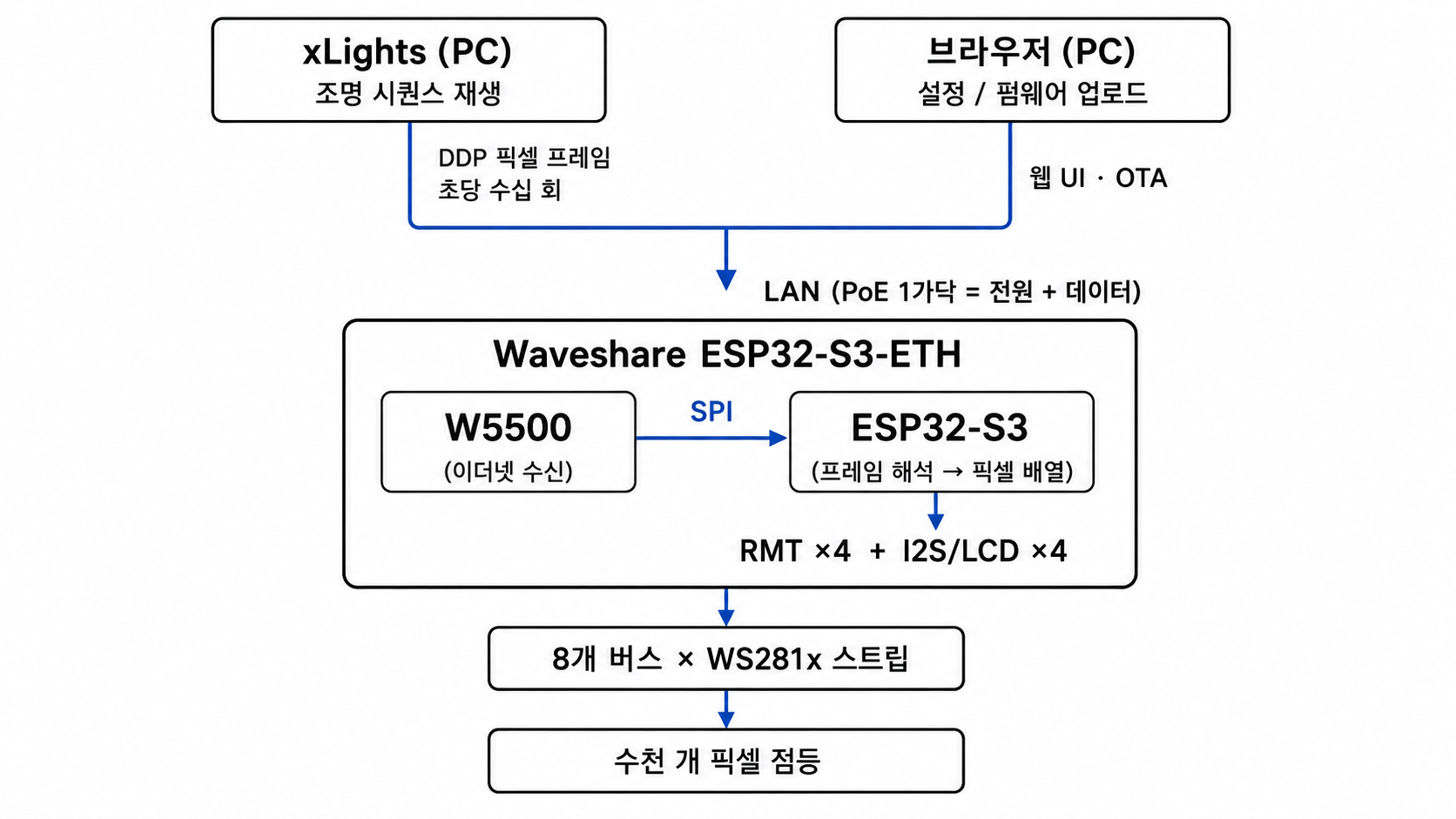
대형 설치물을 위해 WLED는 네트워크로 들어오는 실시간 픽셀 데이터도 받는다. 업계가 이미 쓰고 있는 프로토콜 그대로다 — DDP, E1.31(sACN), Art-Net. PC에서 xLights 같은 시퀀싱 소프트웨어가 프레임을 연속으로 쏘면, 컨트롤러는 자율적으로 동작하는 기기가 아니라 렌더링 종단점이 된다.
🔷 이 모델이 깨지는 지점 — 그리고 이 저장소가 존재하는 이유
웹 UI는 컴파일된 바이너리 안에 존재하는 기능만 노출할 수 있다. 코드에 없는 것은 아무리 설정을 뒤져도 나타나지 않는다.
Waveshare ESP32-S3-ETH 보드에는 SPI로 연결된 WIZnet W5500 이더넷 컨트롤러가 달려 있다. 그런데 WLED 업스트림의 이더넷 지원은 오직 ESP32 내장 EMAC에 붙는 RMII PHY만을 전제로 설계되어 있다. EMAC은 ESP32-S3에 물리적으로 존재하지 않는 페리페럴이다. S3에서 WLED 기본 이더넷 보드 테이블은 이 보드를 목록에 없는 정도가 아니라, 빌드 자체가 컴파일을 거부한다.
wled-custom-builds는 정확히 이런 종류의 공백을 메우기 위해 존재한다. 구체적으로 세 가지 일을 한다.
① 설정 프리셋이 아니라, 보드별 소스 수정본을 담고 있다. 지원하는 보드마다 폴더가 있고, 그 안에는 업스트림 WLED 소스를 직접 수술하는 .patch 파일들이 들어 있다 — network.cpp 등. 여기에 더해 메인테이너가 직접 고쳐야 했던 라이브러리의 벤더링 사본, 커스텀 파티션 테이블 .csv, 핀 배치와 플래시 동작을 정의하는 PlatformIO 환경 조각이 함께 들어 있다. W5500 이더넷 지원은 새로 작성된 드라이버 통합 코드이지, 있는 옵션을 켠 것이 아니다. 업스트림 WLED는 빌드할 때마다 깨끗하게 새로 받아오고 그 위에 오버레이를 얹는 구조라, 엔진 코어는 항상 최신이면서 보드 작업은 분리된 채로 유지된다.
이 보드는 실제로 세 개의 빌드 라인을 갖고 있다. v15(WLED 0.15.x, 보존·동결 상태로 더 이상 개발되지 않음), v16(WLED 16.0.1, W5500 하드웨어 소켓 이더넷), v17(WLED main, 네이티브 lwIP W5500 — 권장 라인). 이 큐레이션이 다루는 것은 이더넷 아키텍처 작업이 담긴 v16과 v17이다.
② 그 타겟들을 빌드해서 완성된 바이너리를 배포한다. GitHub Actions는 targets/** 또는 워크플로 파일 자체를 건드리는 푸시·PR에서만 빌드한다. 트리거를 의도적으로 좁게 잡은 것이다. 실행마다 날짜별 로그와 빌드 메타데이터 JSON을 남기며, GitHub Releases에 발행한다 — 단, 푸시 커밋 메시지에 release라는 토큰이 있을 때만. 여기에 legacy를 덧붙이면 최신이 아닌 프리릴리스로 표시된다. WLED 사용자 대부분은 개발 환경이 없어서 소스에서 빌드할 수 없다. 그래서 바로 구울 수 있는 바이너리를 제공하는 것이 배포 측면의 존재 이유 전부다.
③ 모든 릴리스를 두 개의 산출물로 나눈다. 펌웨어 업데이트가 실패해도 살아남을 수 있게 하기 위해서다. 이 부분이 저장소 자체 문서의 대부분을 차지하며, 명확한 설명이 필요하다.
🔷 OTA에 대하여: 무엇이 원래 WLED의 것이고, 이 저장소가 실제로 만든 것은 무엇인가
OTA(무선 펌웨어 업데이트)는 WLED에 원래 있는 기본 기능이다.WLED에서 OTA는 이렇게 동작한다. 보드의 웹 UI를 열고, 설정 → Security & Updates로 들어가서, 내 PC에 있는 펌웨어 파일을 업로드한다. 보드는 그것을 여분의 애플리케이션 파티션에 기록하고 새 이미지로 재부팅한다.
이것이 여기서 그토록 중요한 이유는 설치 환경 때문이다. 이런 컨트롤러들은 영구 설치된다 — 파사드 12미터 높이, 무대 리그 내부, 벽 뒤. 시공이 끝난 뒤 USB 케이블을 꽂으려면 사다리와 출장이 필요하다. OTA는 노트북에서 5분 만에 끝나느냐, 현장에 사람이 나가느냐의 차이다.
이 저장소가 그 기능을 둘러싸고 만든 것은 두 가지다.
첫째, 두 개의 산출물로 나눈 릴리스 형식. 모든 릴리스는 다음을 발행한다.
| 산출물 | 전달 방식 | 언제 쓰는가 |
|---|---|---|
wled-<version>-<target>-<suffix>.app.bin | OTA — 보드 웹 UI로 업로드 | 지금 정상 동작 중이고 접속 가능한 보드를 업데이트할 때 |
wled-<version>-<target>-<suffix>.full.bin | USB/UART — esptool로 플래싱 | 새 보드, 응답 없는 보드, 또는 파티션 레이아웃이 바뀐 뒤 |
.full.bin은 부트로더, 파티션 테이블, 애플리케이션을 하나의 이미지로 합친 것이다. 부트로더는 전원이 들어오면 가장 먼저 실행되어 어느 애플리케이션 파티션으로 부팅할지 결정하는 작은 프로그램이고, 파티션 테이블은 플래시 어디에 무엇이 있는지 알려주는 지도다. 이것을 만드는 빌드 단계는 세 입력 중 하나라도 없으면 요란하게 실패한다. 릴리스 페이지에 덜 만들어진 복구 이미지가 올라가는 것은 아예 이미지가 없는 것보다 나쁘기 때문이다.
이 분리가 존재하는 이유는, OTA에 소프트웨어적으로 빠져나갈 수 없는 실패 모드가 있어서다. 파티션 레이아웃이 기기에 올라간 것과 다른 빌드는 .app.bin으로 전달할 수 없다. 그리고 플래시 모드 헤더가 어긋나면 애플리케이션 코드가 한 줄도 실행되기 전에 ROM 내부에서 부트루프에 빠지며, 시리얼 출력이 전혀 나오지 않는다 — USB로 칩을 지우는 것 말고는 복구 방법이 없다. 문서화된 규칙은 한 문장이다. OTA가 거부되거나 이후 부팅이 안 되면, 대응되는 .full.bin을 UART로 플래싱하라.
02 — 왜 LED 제어에 이더넷인가?
🔷 리얼타임 픽셀 프로토콜은 재전송을 봐주지 않는다
DDP와 E1.31은 재전송이 없고 데드라인이 명확한 UDP 스트림이다. 늦게 도착한 프레임은 쓸모없는 정도가 아니라 방해가 된다 — 렌더러는 이미 다음 프레임으로 넘어갔기 때문이다. 웹 브라우징에서 Wi-Fi를 쓸 만하게 만들어주는 재시도와 백오프 동작이, 픽셀 스트리밍에서는 정확히 그 반대로 작동한다. 전문 조명이 유선 이더넷 위에서 도는 이유가 이 결정론적 지연 특성이다.
🔷 상설 설치에는 상설 링크가 필요하다
설치형 컨트롤러는 시공이 끝나면 물리적으로 접근이 어려운 경우가 대부분이다. 이더넷 + PoE는 케이블 하나로 전원과 데이터를 모두 공급하고, 수년간 유지되며, 문제가 생기면 스위치 포트 쪽에서 진단할 수 있는 링크를 준다.
🔷 ESP32-S3에는 EMAC이 없다 — 그래서 PHY는 SPI에 붙어야 한다
이 제약이 이 프로젝트를 WIZnet 이야기로 만든다. 구형 ESP32는 LAN8720 같은 RMII PHY를 직접 구동할 수 있었다. S3는 못 한다. S3에서의 이더넷은 반드시 SPI를 거쳐야 하고, SPI 이더넷 선택지는 사실상 ENC28J60, W5500, 그리고 WIZnet의 형제 칩들뿐이다.
🔷 WIZnet 라인업에서 W5500의 위치
(이 소절의 칩 간 비교는 일반적인 배경 설명이며 저장소가 주장한 내용이 아니다. 보드에 W5500이 이미 실장되어 출하되므로 메인테이너가 대안을 평가한 적은 없다.) W5500은 이 급의 설계에서 WIZnet의 주력 선택지다. 하드웨어 소켓 8개, 내장 TX/RX 버퍼 32KB, 최대 80MHz SPI, 10/100 이더넷. 생태계가 비슷하게 갖춰진 유일한 대안인 ENC28J60과 비교하면 여기서 중요한 축 전부에서 W5500이 앞선다 — ENC28J60은 10Mbps 전용이고, 하드와이어드 TCP/IP 스택이 아예 없으며, 에라타 대응으로 드라이버가 복잡해지기로 유명하다. WIZnet 내부에서 보면 W6100은 IPv6 듀얼스택을 더하고, W6300은 QSPI 호스트 인터페이스로 처리량 상한을 올리며, W55RP20은 W5500급 MAC/PHY와 RP2040을 한 패키지에 통합한다. 연산을 담당할 ESP32-S3가 이미 있는 보드라면, W5500의 평범한 SPI 인터페이스와 성숙한 드라이버 생태계가 정확히 알맞은 선택이다.
03 — 시스템 아키텍처
04 — 왜 WIZnet W5500인가? ⭐
🔷 아키텍처 선택지를 실제로 제공하는 유일한 SPI 이더넷 칩
이 프로젝트를 연구할 가치가 있는 핵심이 여기 있다. 대부분의 이더넷 컨트롤러는 통합 모델이 하나뿐이다. W5500은 두 개를 제공하고, 이 프로젝트는 한 엔지니어가 같은 하드웨어에서 두 가지를 모두 구현하고 각각의 실측 결과를 공개한 드문 사례다.
🔷 모드 1 — TOE 하드웨어 소켓 (v16 라인)
v16 라인은 W5500을 WIZnet이 설계한 그대로, 자족적인 하드웨어 TCP/IP 소켓 엔진으로 사용한다. 호스트는 최소 패치를 적용해 벤더링한 Ethernet_Generic 라이브러리를 통해 W5500과 통신하며, ESP32의 lwIP가 아니라 칩 자체의 하드와이어드 스택 위에 소켓을 연다. 메인테이너 본인의 정리에 따르면 이것이야말로 W5500의 진짜 차별화 하드웨어 — 실리콘 소켓 엔진 — 이고, 이를 쓴다는 건 실제 프로토콜 오프로드를 의미한다. ESP32 CPU는 TCP 상태 머신도, 체크섬도, 재전송 타이머도 건드리지 않는다.
하드웨어 검증 결과: SPI로 칩 인식(hardwareStatus=3), 링크 감지(linkStatus=1), DHCP 임대 획득, 그리고 Wi-Fi와 이더넷이 서로 다른 IP로 동시에 동작하며 WLED 정보 패널에 나란히 표시되는 것까지 확인.
그리고 두 번 재현된, 문서화된 한계: WLED의 애플리케이션 트래픽은 단 하나도 이 경로를 지나가지 않는다. WLED의 DDP, E1.31, 웹 UI, MQTT 핸들러는 전부 AsyncTCP/AsyncUDP에 바인딩되어 있고, 그건 ESP32의 lwIP에 하드와이어되어 있다. W5500의 하드웨어 소켓 API는 병렬로 존재하는 두 번째 네트워크 스택이며, WLED 프로토콜 계층의 어떤 코드도 그 API를 쓸 줄 모른다. v16 펌웨어의 이더넷 IP로 DDP를 보내도 스트립은 켜지지 않는다.
이건 W5500의 결함이 아니다. 하드웨어 TCP/IP 오프로드가 상위 애플리케이션에 요구하는 조건을 정확히 진술한 것이다 — 애플리케이션이 오프로드 엔진의 소켓 API를 향해 작성되어 있어야 한다. AsyncTCP에 묶인 네트워킹 코드가 수만 줄인 lwIP 네이티브 코드베이스 WLED는 그렇지 않다. 메인테이너는 이걸 해결하려면 무엇이 필요한지까지 산정했다 — WLED의 웹/소켓 계층 과 리얼타임 프로토콜 수신부를 W5500 소켓 API 기반 코드로 교체해야 하며, 이건 타겟 오버레이가 아니라 WLED 네트워킹 코어의 상시 유지 포크(standing fork)라는 결론이다.
🔷 모드 2 — 네이티브 lwIP 하위의 MACRAW (v17 라인)
v17 라인은 반대 길을 택한다. ESP-IDF 5.5.4 / arduino-esp32 Core 3.3.8에는 W5500을 MACRAW 모드로 구동하는 일급 ETH_PHY_W5500 드라이버가 들어 있다. 생 이더넷 프레임이 그대로 오가고, 프로토콜 처리는 전부 ESP32의 lwIP가 담당한다. W5500은 사실상 매우 얌전한 SPI 부착형 MAC/PHY가 되며, 시스템의 나머지 부분 입장에서는 RMII PHY와 구분되지 않는다.
효과는 완전하다. 진짜 lwIP netif이기 때문에 DDP, E1.31, Art-Net, MQTT, 웹 UI, OTA가 프로토콜별 글루 코드 한 줄 없이 자동으로 이더넷을 타고 동작한다. 대가도 그만큼 분명하다. 하드와이어드 TCP/IP 엔진은 놀고, ESP32 CPU가 스택을 짊어진다.
이 오프로드 대 스택 호환성의 맞교환이 W5500 통합의 근본적인 의사결정이며, 이 프로젝트는 공개 저장소에서 볼 수 있는 그 맞교환의 가장 명확한 실세계 서술이다.
🔷 릴리스 파이프라인 자체가 OTA 안전성을 중심으로 설계됨
메인테이너의 빌드 시스템은 업데이트 경로를 부산물이 아니라 일급 산출물로 취급한다. 모든 릴리스는 타겟당 정확히 두 개의 정규화된 아티팩트를 발행한다:
wled-<version>-<target>-<suffix>.app.bin— OTA 이미지. 정상 동작 중인 기기에 WLED 설정 → Security & Updates → Manual OTA 페이지로 올린다.wled-<version>-<target>-<suffix>.full.bin— 부트로더 + 파티션 테이블 + 애플리케이션을 합친 이미지. 최초 UART 플래싱용이자, OTA가 실패했거나 파티션 레이아웃이 바뀐 경우의 복구용.
.full.bin은 esptool.py merge_bin 단계로 만들어진다. S3 기준 부트로더를 0x0, 파티션 테이블을 0x8000, 애플리케이션을 0x10000에 배치하며, 세 입력 중 하나라도 없으면 요란하게 실패한다. 덜 만들어진 복구 이미지가 릴리스 페이지에 올라가는 일이 원천적으로 불가능하다는 뜻이다. .full.bin은 애초에 기기가 이미 곤란한 상태일 때 손을 뻗는 아티팩트이기 때문에 이 설계가 중요하다.
문서화된 복구 규칙은 한 문장이고, 현장 기술자 입장에서는 이 저장소 전체에서 가장 쓸모 있는 문장이다. OTA가 거부되거나 이후 부팅이 안 되면, 대응되는 .full.bin을 UART로 플래싱하라. 이 규칙을 필수로 만드는 실패 모드가 둘 있다 — .app.bin만으로는 넘어갈 수 없는 파티션 레이아웃 변경, 그리고 아래에 설명한 플래시 모드 헤더 함정. 후자는 애플리케이션 코드가 돌기 전 ROM 단계에서 부트루프에 빠져 시리얼 출력이 전혀 없다.
v16 라인은 앱 파티션 레이아웃에서의 반복 OTA 및 장기 OTA 동작이 여전히 미검증이라는 점도 정직하게 기록해 두었다. 펌웨어가 사용 가능한 앱 슬롯 중 여유 있는 비율만 차지하고 있지만, 메인테이너는 실제로 해보지 않은 것을 주장하지 않는다. (파티션 용량 수치는 v16 노트 기준이므로, 특정 빌드에 적용하기 전에 현재 .csv로 대조 확인하는 것이 좋다.)
🔷 검증된 증거 ✅
v17 라인의 검증 목록은 실물 보드 2대 기준으로 구체적이다:
- 이더넷 (LAN 및 PoE): pass
- Wi-Fi: pass
- xLights → 이더넷 경유 DDP: pass
- xLights → Wi-Fi 경유 DDP: pass
- 이더넷 경유 웹 UI: pass
- Wi-Fi 경유 웹 UI: pass
- 런타임 LED 버스 재구성 — 재부팅 없이 버스 추가/제거/재설정, RMT 구동 버스와 I2S/LCD 구동 버스 양쪽에서 "앞의 N개 LED 건너뛰기" 포함, 이더넷과 Wi-Fi 양쪽에서: pass
MQTT는 슬쩍 넘어가지 않고 "아직 미검증"이라고 명시되어 있다. 이 정직함은 pass 목록만큼의 가치가 있다.
05 — 핵심 구성 요소
🌐 WIZnet W5500 — 두 빌드 라인에서 TOE와 MACRAW 양쪽 모드 모두 사용
- v16 라인: 하드와이어드 TCP/IP 소켓 엔진(TOE). 패치한
Ethernet_Generic을 벤더링해 구동. 링크업과 DHCP까지 하드웨어 검증됨. WLED 애플리케이션 트래픽은 싣지 않는다는 점이 함께 문서화됨. - v17 라인 (권장): ESP-IDF의
ETH_PHY_W5500을 통한 MACRAW 모드. 시스템에는 네이티브 lwIP 인터페이스로 노출되며, WLED의 모든 트래픽이 이 경로를 지나간다. - SPI 핀맵은 두 라인 동일:
MISO=12 MOSI=11 SCLK=13 CS=14 INT=10 RST=9. Waveshare 핀아웃 다이어그램과 대조 확인됨. - v17 패치는
xml.cpp에 예약 핀 보고를, 정보 패널(json.cpp/data/index.js)에 Wi-Fi와 이더넷 IP 동시 표시를 추가한다. 덕분에 W5500의 핀과 링크 상태가 WLED 자체 UI에 드러난다.
🧠 Waveshare ESP32-S3-ETH
ESP32-S3, 플래시 16MB, PSRAM 8MB, PoE 지원 W5500 이더넷. 내장 EMAC이 없다 — 그래서 여기서 W5500은 편의 사양이 아니라 필수 조건이다.
💡 8 × WS281x LED 버스
RMT 하드웨어 채널 4개와 I2S/LCD 병렬 채널 4개로 구동되며, WLED의 버스 매니저가 런타임에 범용적으로 처리한다. v17 라인에서는 데이터 핀 순서를 의도적으로 18,17,16,15,3,2,1,21로 재배치했다. GPIO0을 세트에서 빼고 — S3 스트래핑 핀이자 BOOT 버튼과 공유되는 핀 — W5500 SPI 핀, SD 카드, USB와 겹치지 않는 여유 핀 GPIO21로 대체했다.
🏗️ 타겟 계층형 빌드 시스템
targets/<target>/shared/가 보드별 단일 진실 소스이고, targets/<target>/v15|v16|v17/은 버전 델타만 담는다. scripts/build-target.sh가 매니페스트를 읽고, WLED 베이스를 해석하고(로컬 체크아웃 우선, 없으면 업스트림 fetch), 타겟 오버레이를 적용한 뒤 빌드한다. 실행할 때마다 logs/<target>/<version>/<YYYYMMDD>/ 아래에 날짜별 로그, 메타데이터 JSON, 요약본을 기록하고, 최신 성공 실행본을 latest/에 복사한다.
🚀 토큰 게이트 방식의 CI 릴리스 파이프라인
GitHub Actions가 관련 푸시마다 아티팩트를 빌드하지만, GitHub Release는 커밋 메시지에 release 토큰이 들어 있을 때만 발행된다. release legacy면 프리릴리스로 발행된다. 배포 펌웨어 이름은 OTA용 wled-<version>-<target>-<suffix>.app.bin과 최초 UART 플래싱용 .full.bin으로 정규화되며, 후자는 부트로더·파티션 테이블·애플리케이션을 하나의 이미지로 합치는 esptool.py merge_bin 단계에서 생성되고 입력이 하나라도 없으면 요란하게 실패한다.
⚠️ 기록해둘 가치가 있는 플래시 모드 함정
이 보드의 플래시는 DIO를 요구하는데, esp32s3 코어에는 DIO 부트로더 ELF가 들어 있지 않다. 그래서 board_build.flash_mode는 qio여야 하고(PlatformIO가 어떤 부트로더를 링크할지 결정), custom_merge_flash_mode는 dio여야 한다(ROM이 부팅 시 실제로 참조하는 값). 이걸 틀리면 애플리케이션 코드가 한 줄도 돌기 전에 ROM 단계에서 부트루프에 빠지고, 시리얼 출력이 전혀 없으며, esptool.py erase_flash로만 복구된다. 다음 사람의 주말을 구해주는 종류의 정보다.
06 — 적용 시나리오
01. 상설 건축 조명 및 홀리데이 라이팅
xLights 시퀀스가 수천 픽셀을 높은 프레임 레이트로 DDP를 통해 구동하고, 컨트롤러는 벽에 고정되어 PoE로 전원을 받으며 물리적으로 손이 닿지 않는 환경. v17 라인이 정확히 이 제품이다 — 케이블 하나, 결정론적 지연, 하드웨어 검증된 이더넷 경유 DDP.
02. 무대·공연장·이벤트 조명
E1.31(sACN)과 Art-Net은 공연 조명 제어의 모국어다. 관객 수백 명의 휴대폰이 2.4GHz 대역을 포화시키는 공연장은 Wi-Fi 픽셀 스트리밍에 최악의 환경이자, W5500 업링크를 정당화하는 최선의 근거다.
03. W5500 통합 의사결정을 위한 레퍼런스 설계
"W5500의 하드웨어 TCP/IP 스택을 쓸까, 아니면 MACRAW PHY로 쓸까?"라는 질문 앞에 선 엔지니어라면, 이제 양쪽 분기에 대해 문서화되고 하드웨어로 검증된 답을 각각 어떤 조건에서 유리한지까지 포함해 얻을 수 있다. 요약하면 이렇다: 애플리케이션 계층을 내가 통제하면 TOE, 기존 lwIP 네이티브 스택에 통합하는 상황이면 MACRAW.
04. PoE 한 가닥으로 이루어지는 원격 플릿 유지보수
관리형 스위치 하나 뒤에 컨트롤러 20대가 걸린 공연장. v17 라인은 OTA를 이더넷으로 실어 나르므로, 같은 네트워크에 붙은 노트북 하나로 전체 플릿을 업데이트할 수 있다. Wi-Fi 자격 증명을 기기마다 넣을 필요도 없고, 장비마다 사다리를 탈 일도 없으며, 응답이 없는 유닛은 스위치 포트 쪽에서 링크 상태를 진단할 수 있다. 20대 중 한 대가 업데이트를 깔끔하게 받지 못했을 때를 위해 .app.bin / .full.bin 이분법이 결정론적인 복구 시나리오를 제공한다.
05. 보드별 펌웨어 포크 유지보수의 템플릿
타겟/버전 오버레이 모델, 매니페스트 폴백 체인, 토큰 게이트 릴리스 워크플로, 패치 드리프트 검사기(scripts/check-target-patches.sh)는 빠르게 움직이는 업스트림의 커스텀 빌드를 유지보수하는 모든 사람에게 재사용 가능한 패턴을 이룬다. 임베디드 오픈소스 세계의 상당 부분이 여기에 해당한다.
결론
이 프로젝트는 "W5500이 WLED와 되나?"라는 질문을, 훨씬 유용한 무언가로 바꿔놓았다 — 실제 애플리케이션에서 W5500의 두 가지 통합 모드가 각각 무엇을 제공하는지에 대한 하드웨어 검증된 나란한 비교이며, 부정 결과까지 공개할 만큼 정직하다.
- ✅ 내장 EMAC이 없는 ESP32-S3에서, RMII 전용인 WLED 기본 이더넷 테이블이 컴파일조차 거부하는 상황을 뚫고 W5500 이더넷을 동작시킴
- ✅ 동일 보드에서 W5500 통합 모델 두 가지 — TOE 하드웨어 소켓(v16)과 네이티브 lwIP 하위 MACRAW(v17) — 를 모두 구현하고 하드웨어 검증
- ✅ TOE 오프로드가 왜 lwIP 네이티브 애플리케이션의 트래픽을 네트워킹 코어 재작성 없이는 실어 나를 수 없는지를, 재현된 증거와 함께 문서화
- ✅ DDP, E1.31, 웹 UI가 이더넷 위에서 동작함을 실물 보드 2대로 검증한 v17 라인을 제공. OTA와 MQTT는 같은 lwIP 경로를 구조적으로 따라감
- ✅ OTA는 애플리케이션이 바인딩된 스택을 따라간다는, 배포에 결정적인 귀결을 드러냄 — 이더넷 경유 펌웨어 업데이트가 lwIP 라인에서만 가능하다는 사실이, 아키텍처 선택을 곧 유지보수 가능성의 문제로 바꿔놓는다
- ✅ 실제 결함 4건의 근본 원인 규명 및 수정. 그중 3건은 이더넷과 무관하게 모든 ESP32-S3 사용자에게 영향을 주던 업스트림 버그
- ✅ 복구 불가능한 부트루프로 나타나는 ROM 단계 플래시 모드 함정(
qio부트로더 헤더 vsdio병합 헤더)을 문서화 - ✅ W5500을 WLED 자체 UI에 노출 — 예약 핀 보고 및 정보 패널의 Wi-Fi/이더넷 IP 동시 표시
- ✅ 날짜별 로그, 빌드 메타데이터, 토큰 게이트 릴리스, 정규화된
.app.bin/.full.bin아티팩트를 갖춘 재현 가능한 타겟/버전 오버레이 파이프라인 구축 - ✅ 검증되지 않은 항목(MQTT, 핫플러그 감지, 3MB 레이아웃에서의 장기 OTA)을 과대 주장 없이 명시
Q&A
Q. v17 라인은 W5500의 하드웨어 TCP/IP 엔진을 낭비하는 것 아닌가? 엄밀히 말하면 그렇다 — MACRAW 모드는 하드와이어드 스택을 우회하고 ESP32가 소프트웨어로 프로토콜을 처리한다. 하지만 이 애플리케이션에서 중요한 일은 여전히 W5500이 한다. EMAC이 없는 칩에서 유선 이더넷 자체를 가능하게 만드는 MAC/PHY이고, 연결은 단순한 SPI 버스이며, ESP-IDF에 성숙한 드라이버가 있다. 32KB 내장 버퍼는 여전히 버스트를 흡수하고, L1/L2 처리는 전부 칩이 담당한다. 네트워킹 계층 전체가 lwIP에 묶인 애플리케이션이라면 이건 올바른 엔지니어링 맞교환이다.
Q. 그러면 W5500의 TOE 모드는 언제 써야 하나? 애플리케이션 계층을 내가 소유할 때다. 신규 개발 펌웨어 — 산업용 Modbus TCP 게이트웨이, 데이터 로거, 목적 특화 HTTP/MQTT 디바이스 — 를 W5500 소켓 API에 맞춰 직접 작성하면 이점을 전부 가져간다. 플래시에 소프트웨어 TCP/IP 스택이 없고, 체크섬과 재전송에 CPU 사이클을 쓰지 않으며, 소켓 동작이 결정론적이다. v16 라인의 발견은 "TOE가 열등하다"가 아니라 "TOE는 애플리케이션이 그것을 향해 작성되어 있기를 요구한다"이며, 이건 W5500이 아니라 WLED에 대한 진술이다.
Q. 또 다른 흔한 SPI 이더넷 선택지인 ENC28J60은 왜 안 되나? 먼저 짚어둘 것은 저장소가 이 질문을 던진 적이 없다는 점이다. 보드에 W5500이 실장된 채로 출하되므로 선택 과정 자체가 없었다. 일반적인 배경으로 답하면, ENC28J60은 10Mbps 전용이고, 하드와이어드 TCP/IP 스택이 아예 없어서 TOE라는 선택지 자체가 존재하지 않으며, 드라이버 생태계에 에라타 우회의 역사가 길다. W5500은 10/100이고, 하드웨어 소켓 8개와 32KB 버퍼를 갖췄고, SPI를 최대 80MHz까지 쓰며, ESP-IDF에 ETH_PHY_W5500이라는 일급 드라이버 지원이 있다 — 바로 그 지원이 v17 라인을 가능하게 만들었다.
Q. 실제로는 어떤 빌드를 플래싱해야 하나? 하드웨어 소켓 방식 자체를 연구할 목적이 아니라면 v17 라인이다. 정상 동작 중인 기존 설치에 OTA로 올릴 때는 .app.bin, 새 보드·벽돌 상태·파티션 레이아웃 변경 후에는 UART로 .full.bin을 쓴다.
Q. 이더넷으로 펌웨어 업데이트가 가능한가? 메인테이너 본인의 서술에 따르면 v17 라인에서 가능하다. 다만 해당 라인의 하드웨어 검증 목록에 OTA가 항목으로 올라와 있지는 않으므로, 별도로 측정된 결과라기보다 구조적으로 타당한 상태로 받아들이는 것이 맞다. WLED의 OTA 엔드포인트는 나머지 기능과 함께 lwIP/AsyncTCP 위에 있어서, lwIP가 소유한 인터페이스를 통해서만 기기에 도달한다. v17에서는 W5500 자체가 lwIP 인터페이스이므로 추가 코드 없이 이더넷 OTA가 동작한다. v16에서는 W5500이 별도의 하드웨어 소켓 스택을 돌리고 OTA는 그쪽으로 들어갈 경로가 없다 — 이더넷 포트에 IP는 있지만 그 주소로 펌웨어를 밀어 넣을 수 없고, 업데이트는 Wi-Fi로 가야 한다. 쓸 만한 Wi-Fi가 없는 설치 현장이라면 이 차이가 곧 원격 업데이트냐 출장이냐의 차이다.
Q. OTA 업데이트가 실패하면 어떻게 되나? 대응되는 .full.bin을 UART로 플래싱하면 된다. 부트로더·파티션 테이블·애플리케이션이 한 이미지에 들어 있어서, 실패한 업데이트가 기기를 어떤 상태로 만들어놨든 복구된다. 이걸 선택이 아니라 필수로 만드는 상황이 둘 있다. 기기에 올라간 것과 파티션 레이아웃이 다른 빌드(이건 .app.bin만으로는 해결이 안 된다), 그리고 플래시 모드 헤더 불일치(애플리케이션 코드가 돌기 전 ROM 내부에서 부트루프에 빠지고 시리얼 출력이 전혀 없다). 잃으면 안 되는 설치 현장이라면 UART 어댑터를 현장에 비치해 두는 게 좋다.
Q. 앞으로 나올 WIZnet 칩이 이 맞교환을 바꿀 수 있을까? 개인적인 생각으로는 충분히 가능하다. W6300의 QSPI 호스트 인터페이스는 SPI 측 상한을 크게 끌어올리고, W55RP20은 MCU와 W5500급 MAC/PHY를 한 패키지로 통합한다 — 처음부터 TOE 모드가 자연스러운 선택인 신규 컨트롤러 설계에 특히 매력적인 조합이다.
Original Link: https://github.com/johnvoipguy/wled-custom-builds
Target detail: targets/waveshare-esp32s3-eth/README.md · v17 notes · v16 notes
License: EUPL-1.2