
W6300-based 2-port Ethernet setup on the RP2350 (loopback example)
This project explains how to configure dual Ethernet interfaces on the RP23450 using the W6300 and ioLibrary, and also presents a loopback test example with the
Wiznet - W6300
x 1
PROJECT DESCRIPTION
Setting up 2-ports Ethernet on the RP2350 using the W6300 and Iolibrary
In this project, we focus on controlling two W6300 Ethernet chips using the ioLibrary.
By default, the ioLibrary provided by WIZnet is designed to handle only one WIZchip at a time. It doesn’t natively support multi-chip setups, so we had to modify parts of the library to make it work with multiple W6300s.
We also walk through how to design the circuit to properly connect two W6300 chips to the RP2350, covering both hardware considerations and practical implementation tips.
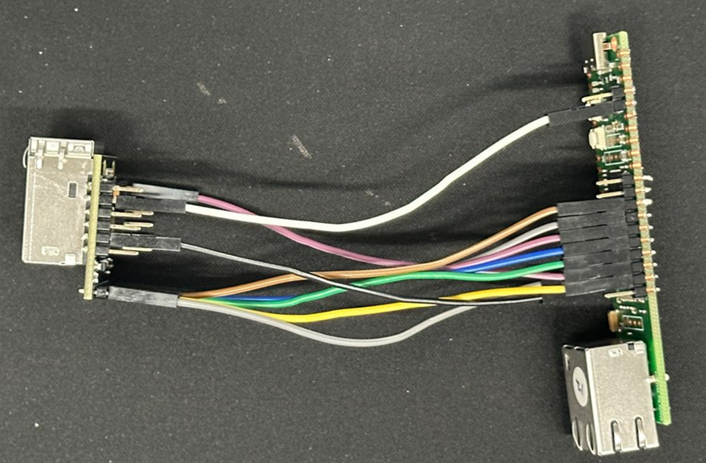
🔌 Circuit Configuration
For this project, we used the following hardware components:
- W6300-EVB-Pico2
- WIZ630io
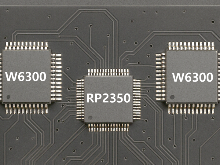
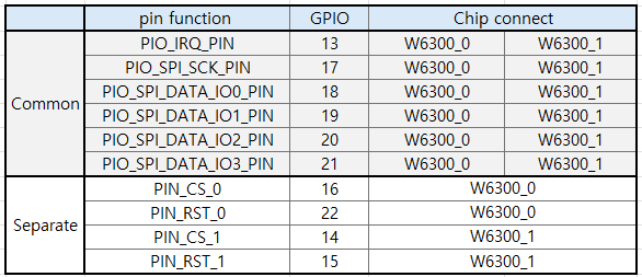
The two W6300 chips share the SPI data lines and clock signal (CLK), while the chip select (CS) and reset (RST) pins are connected to separate GPIOs on the RP2350.
This configuration allows both chips to operate on the same SPI bus, with independent control over selection and reset via software.
🧩 A Simple Trick to Use Two W6300 Chips
In this project, the main goal was to use two W6300 Ethernet chips while making minimal changes to the existing ioLibrary.
Here’s how we approached it:
- The first W6300 uses socket numbers 0–7, just like before.
- The second W6300 is assigned virtual socket numbers 8–15.
This way, it feels like the system supports 16 sockets in total.
⚠️ The Problem
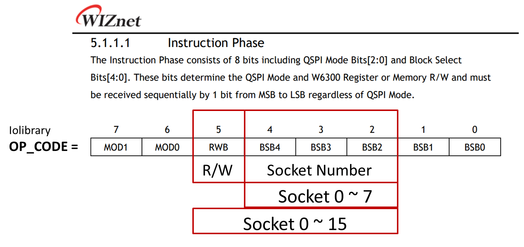
Internally, W6300 uses something called the BSB field to select socket registers.
However, this field is only 3 bits wide, meaning it can represent socket numbers 0–7 only.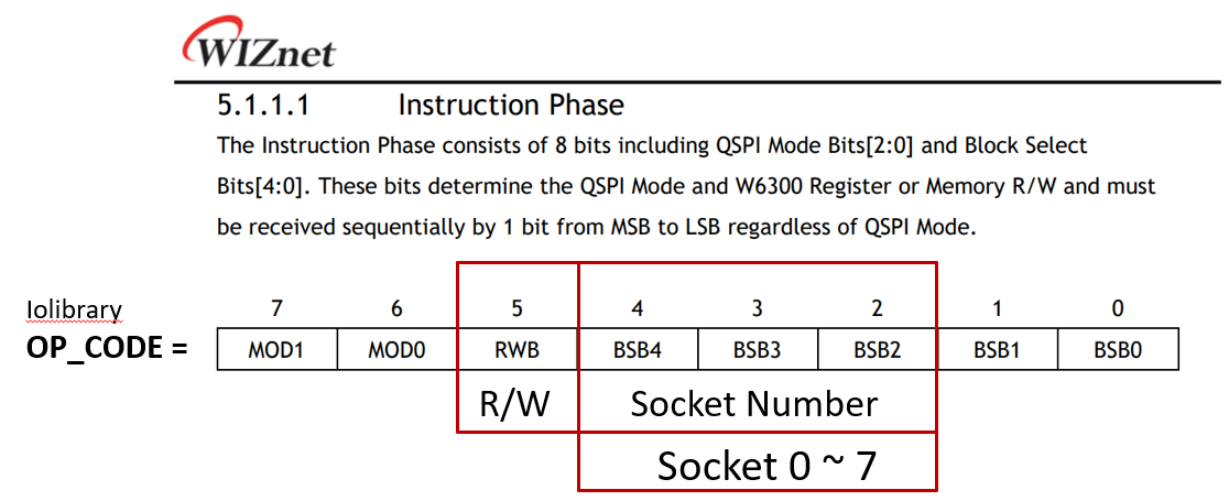
So technically, using socket numbers 8–15 is not allowed and would generate invalid register values.
🔧 How We Solved It
Luckily, the structure of the ioLibrary makes this possible.
Actual SPI communication happens in the following functions:
The R/W bit isn’t important until just before the SPI signal is transmitted.
As long as it's set correctly at that final step, everything works fine.
So here’s the trick:
- We temporarily pretend that sockets 0–15 are valid throughout the upper layers of the code.
- Just before the SPI command is sent, we:
- Clear the RWB bit in the opcode at the beginning.
- Check the socket number and the RWB bit:
- If
RWB == 0and socket number is0–7: select W6300 #0 (CS0) - If
RWB == 1and socket number is8–15: select W6300 #1 (CS1)
- If
- Set the RWB bit properly according to whether it's a read or write operation.
We also borrow 1 bit (the R/W bit) to expand the socket range internally, giving us 4 usable bits in total. That’s how we distinguish between the two chips.
✅ The Result
From the application’s perspective, you just need to assign socket numbers from 0 to 15.
Internally, the system automatically selects the correct chip and sets up the right SPI command.
The ioLibrary remains almost untouched.
loopback TEST
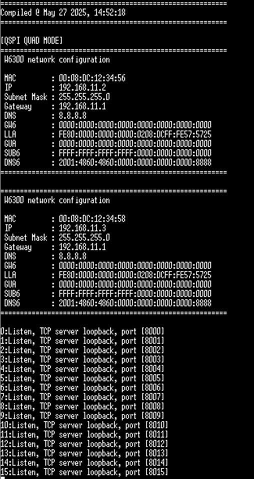
The following log shows the initialization of two W6300 chips,
where each chip is assigned a unique IP address and a loopback server is opened on both.
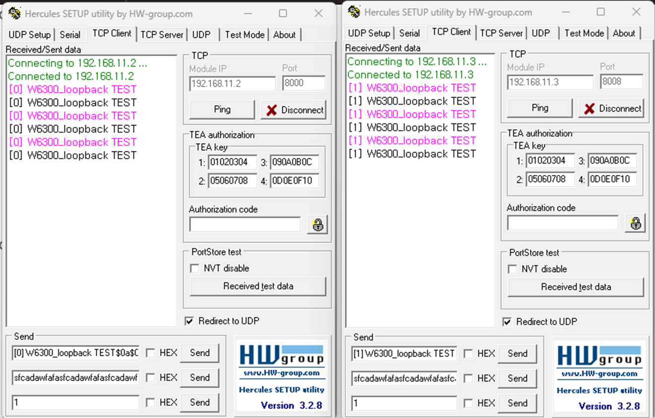
The next screenshot shows the actual loopback communication in action,
demonstrating successful data transmission and reception.
-
WIZnet-PICO-C_2port_W6300
forked from WIZnet-ioNIC/WIZnet-PICO-C
