



sony-camera-bridge
Bringing Legacy Sony RS-422 Camera Control onto Ethernet with W7500P
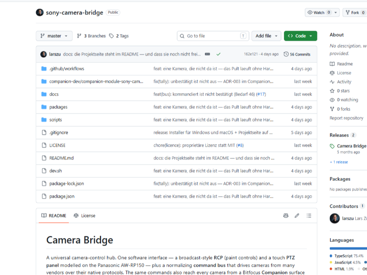
Sony Camera Bridge
Bringing Legacy Sony RS-422 Camera Control onto Ethernet with W7500P
#CameraControl #Broadcast #Sony700PTP #W7500P #TOE #TCP #UDP #RS422 #RCP #PTZ
A unified camera-control project that operates cameras from multiple vendors through one interface and connects legacy Sony RS-422 equipment to an IP network through a W7500P-targeted gateway.
Verification status: The Camera Bridge application and W7500P-targeted firmware source are present in the repository. However, no evidence of execution on physical WIZnet hardware is provided, and the repository’s
WIZ108SR (W7500P)description is technically incorrect.
01 — What is this project?
How are broadcast cameras controlled?
Broadcast studios and live-production venues often operate several cameras at the same time. During production, operators must continuously adjust each camera’s brightness, color, focus, zoom, and viewing direction.
This is normally done with equipment such as an RCP (Remote Control Panel) and a PTZ controller. An RCP adjusts image parameters such as exposure and color, while a PTZ controller remotely controls a camera’s pan, tilt, and zoom movements.
Every manufacturer uses a different control method
The problem is that camera manufacturers do not share one universal control protocol.
Sony uses 700PTP, Canon provides CCAPI, Panasonic uses HTTP CGI, and PTZ cameras may rely on VISCA or vendor-specific REST APIs. Their command formats, connection methods, and supported functions are all different.
As a result, a mixed-camera production may require separate applications or dedicated controllers for each vendor. As the number and variety of cameras grow, operators must learn more equipment and the overall system becomes increasingly complicated.
Camera Bridge brings them together in one interface
Sony Camera Bridge was created to unify these different camera-control methods.
The operator controls cameras from a Web RCP or a touch-based PTZ panel. Camera Bridge receives each action as a common command and translates it into the native protocol understood by the selected camera.
For example, when the operator adjusts the iris, Camera Bridge can send a Sony command to a Sony camera, a CCAPI request to a Canon camera, or an HTTP CGI request to a Panasonic camera. The operator can therefore use the same interface without needing to understand the protocol behind every device.
The repository includes backends for Sony CCU and FX/Alpha cameras, Canon EOS, Panasonic Lumix and AW PTZ, Blackmagic, Z CAM, JVC, BirdDog, and VISCA-over-IP devices. Bitfocus Companion, Stream Deck, and USB control panels can also connect to the same command bus.
How are legacy Sony RS-422 devices connected?
Some Sony broadcast cameras and CCUs (Camera Control Units) are controlled through RS-422 serial communication rather than Ethernet. A CCU is the central device used to manage a broadcast camera’s imaging parameters and operating status.
An RS-422 device cannot communicate directly with the PC running Camera Bridge over TCP/IP. A gateway is therefore required to translate between the RS-422 serial connection and the Ethernet network.
The role of W7500P
The repository contains W7500P-targeted firmware designed to perform this gateway function.
The W7500P receives RS-422 data from the Sony equipment, identifies the boundaries of each Sony 700PTP frame, and forwards the completed command over TCP. In the opposite direction, it receives a TCP command from Camera Bridge and delivers it to the Sony camera or CCU through RS-422.
In this project, the W7500P is not simply a component that adds an Ethernet port. It acts as a dedicated communication gateway that connects legacy Sony RS-422 camera-control equipment to a modern IP-based control environment.
Suggested Image 01 — Project hero image
Show a unified RCP in a broadcast control room, cameras from multiple vendors, and a W7500P gateway connecting legacy Sony RS-422 equipment to Ethernet.
02 — How does the complete system work?
The operator sends commands from one interface
The operator selects and controls a camera through the Web RCP, touch PTZ panel, Bitfocus Companion, or a USB control panel.
Regardless of the control surface, Camera Bridge receives the action in the same common-command format. A new control surface can therefore be added without reimplementing every camera protocol.
Camera Bridge translates commands for each manufacturer
At the center of Camera Bridge is a normalized command bus. It receives common commands such as setIris, setMasterGain, ptz, and recallPreset, then routes them to the backend associated with the selected camera.
Each backend translates the command into the actual protocol used by the device, including Sony 700PTP, Canon CCAPI, Panasonic CGI, and VISCA. If a camera does not support a particular function, the interface disables that control instead of sending an invalid command.
The W7500P gateway is added for legacy Sony equipment
Cameras with native Ethernet protocols communicate directly with Camera Bridge over the network. RS-422-based Sony equipment requires the W7500P gateway between the network and the serial connection.
The complete control path is:
Web RCP → Camera Bridge → TCP/IP → W7500P Gateway → RS-422 → Sony Camera/CCU
This path allows legacy Sony control equipment without a native network interface to become part of the unified camera-control system.
Suggested Image 02 — Complete system architecture
Place the Web RCP, PTZ panel, Companion, and USB panel on the left; Camera Bridge in the center; and the camera backends on the right. Highlight the W7500P → RS-422 → Sony Camera/CCU path along the bottom.
03 — How is this different from a generic serial-to-Ethernet converter?
The limitation of forwarding raw bytes
A typical serial-to-Ethernet gateway collects bytes from a serial port and forwards them over the network according to a configured packet size or timeout. This approach is flexible, but the gateway does not understand where one application command ends and the next begins.
One command may be divided across several TCP packets, or multiple commands may be grouped into one packet. The receiving application must then recover the command boundaries. This can add unnecessary parsing work or delay in a timing-sensitive control protocol.
It recognizes Sony 700PTP frames
The firmware in this project is designed to understand the structure of a Sony 700PTP frame.
It identifies the frame header and length byte in the serial stream, collects the expected payload, and sends the data only after a complete frame has been assembled. It therefore handles data as Sony camera commands rather than as an undifferentiated stream of bytes.
It also recovers from incomplete frames
A frame may be interrupted or unexpected data may appear during communication. If incomplete data remains in the parser for more than 5 ms, the firmware flushes it and resets the parser state.
This behavior is intended to reduce the risk of the parser continuing with incorrect boundaries after synchronization is lost.
The project’s central technical distinction
The proposed W7500P gateway is not merely a generic S2E device. It is designed for a specific application:
A frame-aware gateway that understands Sony 700PTP command boundaries and connects RS-422 to TCP/IP using complete protocol frames.
Suggested Image 03 — Frame-aware conversion process
Show the firmware detecting the header and length in an RS-422 byte stream, assembling a complete 700PTP frame, and forwarding it as one TCP transmission unit.
04 — Why W7500P?
MCU and hardwired TCP/IP in one chip
W7500P combines an ARM Cortex-M0 microcontroller with WIZnet’s hardwired TCP/IP engine in a single chip.
UART data handling, network socket communication, and persistent device configuration can be implemented without combining a separate MCU and Ethernet controller. This helps simplify the hardware architecture of an RS-422-to-Ethernet gateway.
TCP/IP processing is handled in hardware
When a general-purpose MCU uses a software TCP/IP stack, CPU time and memory are consumed by packet processing and connection management. The W7500P performs TCP/IP processing in its hardwired engine, allowing the firmware to concentrate on application work such as UART reception and Sony frame parsing.
This is well suited to a camera-control system where bandwidth is modest but connection stability and responsive command delivery are important.
Socket configuration confirmed in the code
The main Sony control channel uses TOE TCP mode (Sn_MR_TCP) on socket 0. It operates as either a TCP server or client, depending on configuration, and uses port 7700 by default.
Device discovery and network configuration use UDP mode (Sn_MR_UDP) on socket 6. UDP port 5000 carries device-discovery messages and settings such as IP address, gateway, operating mode, baud rate, and parity.
Socket 7 is used by the DHCP client to obtain an IP address automatically. The project does not use MACRAW or IPRAW mode.
Role of each socket
| Socket | Mode | Role |
|---|---|---|
| Socket 0 | TOE TCP | Sony 700PTP data transport |
| Socket 6 | UDP | Device discovery and network/serial configuration |
| Socket 7 | UDP | DHCP client |
Suggested Image 04 — W7500P internal communication structure
Show how TCP socket 0, UDP socket 6, DHCP socket 7, and the UART/RS-422 frame parser interact inside the gateway.
05 — How does the W7500P firmware operate?
1. Load the device configuration
At startup, the firmware loads the MAC address, IP address, TCP port, server/client mode, baud rate, and parity from flash memory.
The default serial configuration is 38400 baud, 8 data bits, odd parity, 1 stop bit, matching the settings described for the Sony connection.
2. Initialize the network and UART
The firmware configures the W7500P socket buffers and network information, then enables the UART receive interrupt. When DHCP is enabled, it requests an IP address from the local network.
3. Manage the TCP connection
In server mode, the gateway waits for Camera Bridge to connect. In client mode, it actively connects to a configured peer IP address and port.
The connection is managed by monitoring the W7500P socket status. When a connection closes, the firmware cleans up the socket and returns it to a state where it can connect again.
4. Forward TCP data to RS-422
When TCP data arrives from Camera Bridge, each byte is passed to the Sony frame parser. After a complete frame is detected, the firmware transmits it to the Sony camera or CCU through UART and the RS-422 interface.
5. Forward RS-422 data to TCP
Data received by the UART interrupt is placed in a ring buffer. The main loop feeds the buffered data into the Sony frame parser and transmits each completed frame through TCP socket 0.
6. Handle device discovery and configuration
When the firmware receives an SBRG_DISCOVER request on UDP port 5000, it responds with device information in JSON format, including firmware version, MAC address, IP address, port, mode, baud rate, and parity.
When it receives an SBRG_CONFIG request, it saves the supplied network and serial settings to flash and restarts the device. This allows the user to discover and configure the gateway from the Camera Bridge interface.
06 — How would a user operate the system?
Connect the equipment
The RS-422 port of the Sony camera or CCU is connected to the serial interface of the W7500P gateway. The gateway’s Ethernet interface is then connected to the same network as the PC running Camera Bridge.
Discover and configure the gateway
The operator searches the local network from the WIZnet configuration screen in Camera Bridge. After the gateway is discovered, the operator configures its IP address, TCP port, server/client mode, RS-422 baud rate, and parity.
Register the camera
The Sony camera or CCU connection is registered in Camera Bridge. Cameras from other manufacturers can also be added by selecting the appropriate backend and entering the required IP address and protocol settings.
Operate everything from one control panel
The operator selects a camera from the Web RCP or touch PTZ panel and adjusts iris, gain, white balance, zoom, focus, or presets.
Commands for Sony RS-422 equipment pass through the W7500P gateway, while network-capable cameras are controlled directly through their native protocols.
07 — Key components
Camera Bridge server
The central server is written in Node.js and TypeScript. It manages the normalized camera commands and dispatches them to manufacturer-specific backends.
Web RCP
The Web RCP provides controls for broadcast-camera parameters including iris, master black, gamma, gain, white balance, shutter, and color bars.
Touch PTZ panel
The touch interface controls pan, tilt, zoom, focus, and camera presets. A PTZ-oriented interface is presented when an appropriate camera is selected.
Camera protocol backends
Each backend translates common commands into the native protocol used by a particular camera. The repository includes Sony, Canon, Panasonic, Blackmagic, Z CAM, JVC, BirdDog, and VISCA implementations.
Bitfocus Companion and USB HID
Stream Deck buttons and physical USB controls are mapped to Camera Bridge commands. Cameras can therefore be operated with physical buttons and knobs as well as the software interface.
W7500P-targeted firmware
The firmware connects Sony 700PTP over RS-422 to TCP/IP. It includes TOE TCP sockets, a UDP configuration protocol, DHCP, flash-based configuration storage, UART interrupt handling, and the frame parser.
08 — Where could it be used?
Broadcast studios using cameras from multiple vendors
Important functions from different camera brands can be accessed through one RCP and PTZ interface.
Facilities that must retain legacy Sony equipment
Sony cameras or CCUs with RS-422 control ports could be connected to an IP-based control environment without replacing the existing equipment.
Remote camera operation in venues and houses of worship
An operator can manage camera direction, zoom, and exposure from a central control room. Companion and Stream Deck can place frequently used functions on dedicated buttons.
Portable production systems
The Electron-based desktop interface can be installed on a laptop to create a portable camera-control station. A Windows installer is available from the repository’s releases.
09 — What is confirmed in the code, and what still requires verification?
Confirmed directly in the repository
W7500P peripheral and WZTOE headers are used
The build configuration references W7500x_Library and ioLibrary_Driver
ARM Cortex-M0 compiler options and a W7500P linker script are present
TOE TCP server/client operation is implemented on socket 0
UDP discovery and configuration are implemented on socket 6
A DHCP client is assigned to socket 7
UART interrupt handling and a ring buffer are implemented
A Sony 700PTP frame parser is present
Network and serial settings are stored in flash
Web RCP, PTZ panel, Companion module, and camera backend sources are present
Electron-based Windows installer releases are available
Items that require physical hardware verification
The exact WIZnet module used
Photographs of the board connected to a Sony camera or CCU
Successful W7500P firmware build and flash records
Actual RS-422 transactions and TCP packet logs
Sony 700PTP frame-boundary behavior on hardware
Long-running connection stability and reconnection behavior
Incorrect hardware identification
The repository describes the target hardware as WIZ108SR (W7500P). This combination does not exist. WIZ108SR is based on W7100A and does not contain a W7500P. The compatible W7500P-based module is WIZ750SR.
The current source therefore cannot be firmware for a real WIZ108SR. Its MCU architecture indicates a W7500P-based target, but the repository does not prove that a physical WIZ750SR was used.
Before this project can be presented as a verified hardware implementation, the author should correct the target module name and provide validated pin mapping and hardware test evidence.
Conclusion
Sony Camera Bridge addresses the challenge of operating cameras from different manufacturers—and legacy serial broadcast equipment—within one IP-based camera-control environment.
Camera Bridge normalizes vendor-specific commands through a common command bus. The W7500P-targeted gateway forms the link between this system and legacy Sony RS-422 equipment, recognizing Sony 700PTP frame boundaries as it transfers commands between TCP/IP and RS-422.
WIZnet’s role in this project is more than basic network connectivity. It provides the connection point that could bring existing broadcast equipment into a modern Ethernet control system without replacing the cameras or CCUs.
Different cameras are unified behind one interface, while a W7500P gateway extends legacy Sony RS-422 control onto the IP network.
However, the hardware product name in the repository is incorrect and no physical-board validation evidence is provided. The software and firmware design can be examined in source, but additional verification is required before describing it as a confirmed WIZnet hardware deployment.
Q&A
Q. What is the main problem this project attempts to solve?
It unifies camera-control protocols from different manufacturers behind one interface and brings RS-422-only Sony equipment into the same IP-based system.
Q. What role does W7500P play in the complete system?
It serves as a dedicated gateway between Camera Bridge commands over TCP/IP and the RS-422 interface of a Sony camera or CCU.
Q. How is it different from a generic serial-to-Ethernet gateway?
Instead of forwarding arbitrary groups of bytes, it is designed to inspect the Sony 700PTP header and length field and forward complete protocol frames.
Q. Which WIZnet socket modes are used?
Sony control data uses TOE TCP mode on socket 0. Device discovery and configuration use UDP mode on socket 6, while socket 7 is assigned to DHCP. MACRAW and IPRAW are not used.
Q. Is this really firmware for WIZ108SR?
No. WIZ108SR is based on W7100A and cannot run the current W7500P Cortex-M0 source. The repository author may have confused it with WIZ750SR, but the physical module actually used is not confirmed.
Q. Can it be built and reproduced directly on hardware?
The firmware source identifies the required libraries, but the external W7500x_Library and ioLibrary_Driver trees must be prepared separately. The target board and pin mapping also require correction and verification, so the repository is not yet a complete hardware-reproduction package.
W7500P로 기존 Sony RS-422 카메라 제어를 Ethernet에 연결하다
#CameraControl #Broadcast #Sony700PTP #W7500P #TOE #TCP #UDP #RS422 #RCP #PTZ
여러 제조사의 카메라를 하나의 화면에서 제어하고, 기존 Sony RS-422 장비는 W7500P 대상 Gateway를 통해 IP Network에 연결하는 통합 카메라 제어 프로젝트입니다.
검증 상태: Camera Bridge Application과 W7500P 대상 Firmware Source는 저장소에서 확인됩니다. 다만 실제 WIZnet Hardware에서 실행한 자료는 없으며, 저장소에 적힌
WIZ108SR (W7500P)는 잘못된 제품 표기입니다.
01 — 이 프로젝트는 무엇인가?
방송 카메라는 어떻게 제어할까?
방송 스튜디오나 공연 현장에서는 여러 대의 카메라를 동시에 사용합니다. 운영자는 촬영 중에도 각 카메라의 밝기와 색상, 초점, Zoom, 촬영 방향을 계속 조정해야 합니다.
이때 사용하는 장비가 RCP(Remote Control Panel)와 PTZ Controller입니다. RCP는 카메라의 노출과 색상을 조정하는 장비이고, PTZ Controller는 원격 카메라의 좌우·상하 이동과 Zoom을 제어하는 장비입니다.
제조사마다 제어 방식이 다르다
문제는 카메라 제조사마다 명령을 전달하는 방식이 다르다는 것입니다.
Sony는 700PTP, Canon은 CCAPI, Panasonic은 HTTP CGI를 사용하며, PTZ 카메라에는 VISCA 또는 제조사별 REST API가 사용됩니다. 명령의 형식뿐만 아니라 연결 방법과 지원 기능도 서로 다릅니다.
따라서 여러 제조사의 카메라를 함께 운용하려면 각각의 전용 프로그램이나 조작 장비를 따로 사용해야 합니다. 카메라 종류가 늘어날수록 운영자가 익혀야 할 장비가 많아지고, 전체 시스템도 복잡해집니다.
하나의 화면으로 통합하는 Camera Bridge
Sony Camera Bridge는 서로 다른 카메라의 제어 방식을 하나로 통합하기 위해 만들어진 프로젝트입니다.
사용자는 Web RCP나 Touch PTZ Panel에서 카메라를 조작합니다. Camera Bridge는 사용자의 명령을 공통 Command로 받아서, 연결된 카메라 제조사가 이해할 수 있는 Native Protocol로 변환합니다.
예를 들어 사용자가 화면에서 Iris를 조절하면 Sony Camera에는 Sony 방식의 명령을, Canon Camera에는 CCAPI 요청을, Panasonic Camera에는 HTTP CGI 요청을 전달합니다. 운영자는 내부 Protocol의 차이를 몰라도 같은 Interface에서 카메라를 제어할 수 있습니다.
저장소에는 Sony CCU와 FX/Alpha, Canon EOS, Panasonic Lumix 및 AW PTZ, Blackmagic, Z CAM, JVC, BirdDog, VISCA over IP 장비를 위한 Backend가 포함되어 있습니다. Bitfocus Companion, Stream Deck, USB 조작 Panel도 같은 Command Bus에 연결할 수 있습니다.
기존 Sony RS-422 장비는 어떻게 연결할까?
일부 Sony 방송용 카메라와 CCU(Camera Control Unit)는 Ethernet이 아닌 RS-422 Serial 통신으로 제어됩니다. CCU는 방송 카메라의 영상 설정과 상태를 중앙에서 관리하는 장비입니다.
RS-422 장비는 Camera Bridge가 실행되는 PC와 직접 TCP/IP 통신을 할 수 없습니다. 따라서 RS-422 Serial 신호와 Ethernet Network 사이에서 데이터를 변환하는 Gateway가 필요합니다.
W7500P의 역할
저장소에는 이 Gateway 역할을 수행하기 위한 W7500P 대상 Firmware가 포함되어 있습니다.
W7500P는 Sony 장비에서 들어오는 RS-422 데이터를 수신하고, Sony 700PTP Protocol의 Frame 경계를 확인한 뒤 완성된 명령 단위로 TCP Network에 전달합니다. 반대 방향으로는 Camera Bridge가 보낸 TCP 명령을 RS-422 신호로 변환하여 Sony Camera나 CCU로 전달합니다.
즉, 이 프로젝트에서 W7500P는 단순히 Ethernet Port를 추가하는 부품이 아닙니다. 기존 Sony RS-422 카메라 제어 장비를 현대적인 IP 기반 통합 제어 환경에 연결하는 전용 통신 Gateway 역할을 담당합니다.
이미지 제안 01 — 프로젝트 대표 이미지
방송 조정실의 통합 RCP 화면과 여러 제조사의 카메라, 그리고 기존 Sony RS-422 장비를 Ethernet에 연결하는 W7500P Gateway를 함께 표현합니다.
02 — 전체 시스템은 어떻게 동작하는가?
사용자는 하나의 Interface에서 명령을 보낸다
운영자는 Web RCP, Touch PTZ Panel, Bitfocus Companion 또는 USB 조작 Panel에서 원하는 카메라를 선택하고 제어합니다.
어떤 조작 장치를 사용하더라도 Camera Bridge에는 동일한 형태의 Command가 전달됩니다. 따라서 새로운 조작 장치를 추가하더라도 각 카메라 Protocol을 다시 구현할 필요가 없습니다.
Camera Bridge가 제조사별 명령으로 변환한다
Camera Bridge 중앙에는 공통 Command Bus가 있습니다. setIris, setMasterGain, ptz, recallPreset과 같은 공통 명령을 받은 뒤, 현재 연결된 Camera Backend로 전달합니다.
각 Backend는 이 명령을 Sony 700PTP, Canon CCAPI, Panasonic CGI, VISCA 등의 실제 Protocol로 변환합니다. 특정 Camera가 지원하지 않는 기능은 Interface에서 비활성화하여 동작하지 않는 명령이 전송되는 것을 막습니다.
기존 Sony 장비에는 W7500P Gateway가 추가된다
Ethernet Protocol을 직접 지원하는 카메라는 Camera Bridge와 Network로 통신합니다. 반면 RS-422 기반 Sony 장비는 중간에 W7500P Gateway가 필요합니다.
전체 제어 경로는 다음과 같습니다.
Web RCP → Camera Bridge → TCP/IP → W7500P Gateway → RS-422 → Sony Camera/CCU
이 경로를 통해 Network에 연결되지 않은 기존 Sony 제어 장비도 통합 Camera Control System의 일부로 사용할 수 있습니다.
이미지 제안 02 — 전체 시스템 아키텍처
왼쪽에는 Web RCP·PTZ·Companion·USB Panel, 중앙에는 Camera Bridge, 오른쪽에는 여러 Camera Backend를 배치합니다. 하단에는 W7500P → RS-422 → Sony Camera/CCU 경로를 강조합니다.
03 — 일반적인 Serial-to-Ethernet 변환과 무엇이 다른가?
단순한 Byte 전달의 한계
일반적인 Serial-to-Ethernet Gateway는 Serial Port에서 받은 Byte를 일정 크기나 시간 단위로 묶어 Network로 전달합니다. 이 방식은 다양한 장비에 범용으로 사용할 수 있지만, 응용 Protocol의 명령 경계를 정확히 알지는 못합니다.
한 개의 명령이 여러 TCP Packet으로 나뉘거나 여러 명령이 한꺼번에 묶이면, 수신 측에서 다시 명령 경계를 찾아야 합니다. Timing에 민감한 제어 Protocol에서는 불필요한 지연이나 Parsing 부담이 생길 수 있습니다.
Sony 700PTP Frame을 인식한다
이 프로젝트의 Firmware는 Sony 700PTP Frame 구조를 인식하도록 설계되어 있습니다.
Serial Data에서 Header와 Length Byte를 확인하고, 해당 길이만큼 Payload를 수집합니다. 하나의 Frame이 완성되면 전체 Frame을 TCP로 전달합니다. 즉, 단순한 Byte Stream이 아니라 Sony Camera가 사용하는 명령 단위로 데이터를 처리합니다.
불완전한 Frame도 복구한다
통신 도중 Frame이 끊기거나 예상하지 못한 데이터가 들어올 수 있습니다. Firmware는 완성되지 않은 데이터가 5ms 이상 남아 있으면 이를 Flush하고 Parser 상태를 초기화합니다.
이 처리는 통신이 한 번 어긋난 뒤 계속 잘못된 경계를 따라가는 문제를 줄이기 위한 장치입니다.
이 프로젝트의 핵심 차별점
이 프로젝트가 제시하는 W7500P Gateway는 범용 S2E 장치가 아니라 다음 목적에 맞춘 전용 Gateway입니다.
Sony 700PTP 명령 구조를 이해하고, 완성된 Frame 단위로 RS-422와 TCP/IP 사이를 연결하는 Frame-aware Gateway
이미지 제안 03 — Frame-aware 변환 과정
RS-422 Byte Stream에서 Header와 Length를 확인하고, 완성된 700PTP Frame을 하나의 TCP 전송 단위로 만드는 과정을 단계별로 표현합니다.
04 — 왜 W7500P를 사용했는가?
MCU와 Hardwired TCP/IP가 하나로 통합되어 있다
W7500P는 ARM Cortex-M0 MCU와 WIZnet의 Hardwired TCP/IP Engine을 하나의 Chip에 통합한 제품입니다.
별도의 Ethernet Controller와 MCU를 조합하지 않아도 UART Data 처리, Network Socket 통신, 장치 설정 저장을 하나의 Chip에서 구현할 수 있습니다. RS-422-to-Ethernet Gateway의 Hardware 구성을 단순하게 만들 수 있는 이유입니다.
TCP/IP 처리를 Hardware에 맡긴다
일반 MCU에서 Software TCP/IP Stack을 사용하면 Packet 처리와 연결 상태 관리에 CPU와 Memory가 사용됩니다. W7500P는 TCP/IP 처리를 Hardwired Engine에서 수행하므로 Firmware는 UART 수신과 Sony Frame Parsing 같은 응용 로직에 집중할 수 있습니다.
Camera Control처럼 전송량은 크지 않지만 연결 유지와 응답성이 중요한 시스템에 적합한 구성입니다.
코드에서 확인되는 Socket 구성
주요 Sony 제어 Data는 Socket 0에서 **TOE TCP Mode(Sn_MR_TCP)**로 처리합니다. 설정에 따라 TCP Server 또는 Client로 동작하며 기본 Port는 7700입니다.
장치 검색과 Network 설정에는 Socket 6의 **UDP Mode(Sn_MR_UDP)**를 사용합니다. UDP Port 5000으로 장치를 검색하고 IP, Gateway, 통신 Mode, Baud Rate 등의 설정을 전달합니다.
Socket 7은 IP Address를 자동으로 할당받기 위한 DHCP Client에 사용됩니다. 이 프로젝트에서는 MACRAW와 IPRAW Mode를 사용하지 않습니다.
각 Socket의 역할
| Socket | Mode | 역할 |
|---|---|---|
| Socket 0 | TOE TCP | Sony 700PTP Data 전달 |
| Socket 6 | UDP | 장치 검색 및 Network·Serial 설정 |
| Socket 7 | UDP | DHCP Client |
이미지 제안 04 — W7500P 내부 통신 구조
TCP Socket 0, UDP Socket 6, DHCP Socket 7과 UART/RS-422 Frame Parser의 관계를 하나의 Block Diagram으로 표현합니다.
05 — W7500P Firmware는 어떻게 동작하는가?
1. 설정을 불러온다
전원이 켜지면 Flash Memory에서 MAC Address, IP Address, TCP Port, Server/Client Mode, Baud Rate와 Parity 설정을 불러옵니다.
기본 Serial 설정은 Sony 통신에 맞춘 38400 baud, 8 data bits, odd parity, 1 stop bit입니다.
2. Network와 UART를 초기화한다
W7500P의 Socket Buffer와 Network 정보를 설정하고 UART 수신 Interrupt를 활성화합니다. DHCP를 사용하도록 설정된 경우 Network에서 IP Address를 자동으로 할당받습니다.
3. TCP 연결을 관리한다
Server Mode에서는 외부 Camera Bridge의 연결을 기다리고, Client Mode에서는 설정된 상대 IP Address와 Port로 직접 접속합니다.
TCP 연결 상태는 W7500P Socket Status를 확인하며 관리합니다. 연결이 종료되면 Socket을 정리하고 다시 연결 가능한 상태로 돌아갑니다.
4. TCP Data를 RS-422로 전달한다
Camera Bridge에서 TCP Data가 들어오면 Sony Frame Parser에 Byte를 순서대로 입력합니다. 완성된 Frame이 확인되면 UART를 통해 Sony Camera 또는 CCU로 전송합니다.
5. RS-422 Data를 TCP로 전달한다
UART Interrupt에서 받은 Data는 Ring Buffer에 저장됩니다. Main Loop는 Buffer의 Data를 Sony Frame Parser에 전달하고, 완성된 Frame을 Socket 0을 통해 TCP로 전송합니다.
6. 장치 검색과 설정을 처리한다
UDP Port 5000에서 SBRG_DISCOVER 요청을 받으면 Firmware Version, MAC Address, IP Address, Port, Mode, Baud Rate 등의 장치 정보를 JSON 형태로 응답합니다.
SBRG_CONFIG 요청을 받으면 전달된 Network 및 Serial 설정을 Flash에 저장하고 장치를 재시작합니다. 이를 통해 사용자는 Camera Bridge의 설정 화면에서 Gateway를 검색하고 설정할 수 있습니다.
06 — 사용자는 이 시스템을 어떻게 사용하는가?
장비를 연결한다
Sony Camera 또는 CCU의 RS-422 Port를 W7500P Gateway의 Serial Interface에 연결하고, Gateway의 Ethernet Port를 Camera Bridge가 실행되는 PC와 같은 Network에 연결합니다.
Gateway를 검색하고 설정한다
Camera Bridge의 WIZnet 설정 화면에서 Network의 Gateway를 검색합니다. 검색된 장치의 IP Address와 TCP Port, Server/Client Mode, RS-422 Baud Rate와 Parity를 설정합니다.
Camera를 등록한다
Camera Bridge에서 Sony Camera 또는 CCU의 연결 정보를 등록합니다. 다른 제조사의 Camera도 각 Backend에 맞는 IP Address와 Protocol을 선택하여 추가할 수 있습니다.
하나의 Control Panel에서 운용한다
운영자는 Web RCP나 Touch PTZ Panel에서 Camera를 선택하고 Iris, Gain, White Balance, Zoom, Focus, Preset 등을 조작합니다.
Sony RS-422 장비로 보내는 명령은 W7500P Gateway를 거쳐 전달되고, Network Camera는 각 제조사의 Native Protocol로 직접 제어됩니다.
07 — 주요 구성 요소
Camera Bridge Server
Node.js와 TypeScript로 작성된 중앙 Server입니다. 공통 Camera Command를 관리하고 Sony, Canon, Panasonic 등 제조사별 Backend로 전달합니다.
Web RCP
방송 카메라의 Iris, Master Black, Gamma, Gain, White Balance, Shutter와 Color Bar 등을 조절하는 Web Interface입니다.
Touch PTZ Panel
Pan, Tilt, Zoom, Focus와 Camera Preset을 Touch Interface에서 제어합니다. PTZ Camera를 선택하면 해당 조작 화면을 사용할 수 있습니다.
Camera Protocol Backend
공통 Command를 각 Camera가 사용하는 Native Protocol로 변환합니다. 저장소에는 Sony, Canon, Panasonic, Blackmagic, Z CAM, JVC, BirdDog 및 VISCA Backend가 포함되어 있습니다.
Bitfocus Companion과 USB HID
Stream Deck Button이나 USB 조작 Panel의 입력을 Camera Bridge Command로 변환합니다. 사용자는 Software 화면뿐만 아니라 물리적인 Button과 Knob로도 Camera를 제어할 수 있습니다.
W7500P 대상 Firmware
Sony 700PTP RS-422 통신과 TCP/IP 사이를 연결합니다. TOE TCP Socket, UDP 설정 Protocol, DHCP, Flash 설정 저장, UART Interrupt 및 Frame Parser를 포함합니다.
08 — 어디에 활용할 수 있는가?
여러 제조사의 카메라를 사용하는 방송 Studio
Camera 제조사가 서로 달라도 하나의 RCP와 PTZ Interface에서 주요 기능을 제어할 수 있습니다.
기존 Sony 장비를 유지해야 하는 현장
RS-422 제어 Port를 사용하는 Sony Camera나 CCU를 교체하지 않고 IP 기반 제어 환경에 연결하는 Gateway로 활용할 수 있습니다.
공연장과 종교 시설의 원격 Camera 운영
운영실에서 여러 Camera의 촬영 방향과 Zoom, 노출을 통합 관리할 수 있습니다. Companion과 Stream Deck을 이용하면 자주 사용하는 기능을 Button으로 구성할 수 있습니다.
이동형 제작 System
Electron 기반 Desktop UI를 Notebook에 설치하여 휴대형 Camera Control Station을 구성할 수 있습니다. 저장소에는 Windows Installer가 공개되어 있습니다.
09 — 코드에서 확인된 내용과 검증이 필요한 부분
저장소에서 직접 확인된 내용
W7500P Peripheral 및 WZTOE Header 사용
W7500x_Library와 ioLibrary_Driver 기반 Build 구성
ARM Cortex-M0 Compiler Option과 W7500P Linker Script
Socket 0의 TOE TCP Server/Client 구현
Socket 6의 UDP 검색 및 설정 Protocol
Socket 7의 DHCP Client 구성
UART Interrupt와 Ring Buffer 구현
Sony 700PTP Frame Parser 구현
Flash 기반 Network 및 Serial 설정 저장
Web RCP, PTZ Panel, Companion Module 및 Camera Backend Source
Electron 기반 Windows Installer Release
실제 Hardware에서 추가 확인이 필요한 내용
사용된 WIZnet Module의 정확한 제품명
실제 Board와 Sony Camera/CCU의 연결 사진
W7500P Firmware Build 및 Flash 성공 기록
실제 RS-422 송수신과 TCP Packet Log
Sony 700PTP Frame 경계 처리 결과
장시간 연결 유지 및 재접속 동작
잘못된 Hardware 표기
저장소는 대상 Hardware를 WIZ108SR (W7500P)로 설명합니다. 그러나 WIZ108SR은 W7100A 기반 제품이며 W7500P를 사용하지 않습니다. W7500P 기반 호환 Module은 WIZ750SR입니다.
따라서 현재 Source는 WIZ108SR용 Firmware가 될 수 없습니다. 코드의 MCU Architecture만 보면 W7500P 기반 Hardware를 대상으로 하지만, 실제로 WIZ750SR을 사용했는지는 저장소만으로 확인되지 않습니다.
이 프로젝트를 실제 Hardware 사례로 소개하려면 작성자가 Target Module의 이름을 수정하고, Pin Mapping과 Hardware 동작 자료를 추가해야 합니다.
Conclusion
Sony Camera Bridge가 해결하려는 핵심 문제는 서로 다른 제조사의 카메라와 기존 Serial 기반 방송 장비를 하나의 IP Camera Control 환경에서 운용하는 것입니다.
Camera Bridge는 여러 제조사의 명령을 공통 Command Bus로 통합합니다. W7500P 대상 Gateway는 이 시스템과 기존 Sony RS-422 장비 사이를 연결하며, Sony 700PTP Frame을 인식하여 TCP/IP와 RS-422 사이에서 전달합니다.
이 프로젝트에서 WIZnet의 의미는 단순한 Network 연결이 아닙니다. 기존 방송 장비를 교체하지 않고 현대적인 Ethernet Control System에 포함할 수 있도록 만드는 연결 지점입니다.
서로 다른 카메라는 하나의 Interface로 통합하고, 기존 Sony RS-422 장비는 W7500P Gateway를 통해 IP Network로 확장합니다.
다만 현재 저장소의 Hardware 제품명은 잘못되어 있으며 실제 Board 검증 자료도 제공되지 않았습니다. 따라서 Software와 Firmware의 설계 가치는 확인할 수 있지만, 실제 WIZnet Hardware 적용 사례로 확정하려면 추가 검증이 필요합니다.
Q&A
Q. 이 프로젝트가 해결하려는 가장 큰 문제는 무엇인가?
서로 다른 제조사의 Camera Control Protocol을 하나의 Interface로 통합하고, RS-422만 지원하는 기존 Sony 장비도 같은 IP 기반 시스템에서 제어하는 것입니다.
Q. W7500P는 시스템 전체에서 어떤 역할을 하는가?
Camera Bridge의 TCP/IP 명령과 Sony Camera·CCU의 RS-422 통신 사이를 변환하는 전용 Gateway 역할을 합니다.
Q. 일반적인 Serial-to-Ethernet Gateway와 무엇이 다른가?
단순히 일정량의 Byte를 전달하는 것이 아니라 Sony 700PTP의 Header와 Length를 분석하여 완성된 Frame 단위로 전달하도록 설계되었습니다.
Q. 어떤 WIZnet Socket Mode를 사용하는가?
Sony 제어 Data에는 Socket 0의 TOE TCP Mode를 사용합니다. 장치 검색과 설정에는 Socket 6의 UDP Mode를 사용하며 Socket 7은 DHCP에 할당됩니다. MACRAW와 IPRAW는 사용하지 않습니다.
Q. 실제 WIZ108SR용 Firmware인가?
아닙니다. WIZ108SR은 W7100A 기반이므로 현재 W7500P Cortex-M0 Source를 실행할 수 없습니다. 저장소 작성자가 WIZ750SR과 혼동했을 가능성이 있지만, 실제 사용 Module은 확인되지 않았습니다.
Q. 바로 Build하고 Hardware에서 재현할 수 있는가?
Firmware Source와 필요한 Library 이름은 제공되지만 외부 W7500x_Library 및 ioLibrary_Driver 준비가 필요합니다. Target Board와 Pin Mapping도 수정·검증해야 하므로 현재 상태를 완전한 재현