
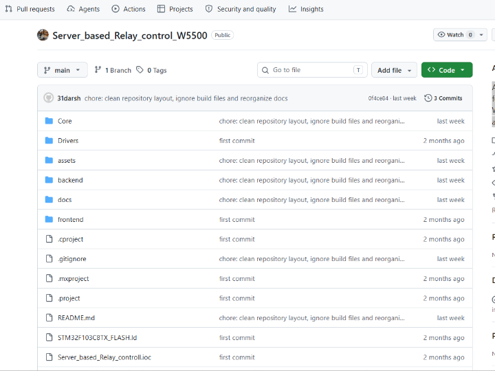
Server_based_Relay_control_W5500
A complete IoT relay control solution featuring STM32 firmware with W5500, a Node.js TCP/HTTP server, and a web admin dashboard.
Server-Based Relay Control System — Industrial-Grade Remote Switching with a Web Dashboard
#RelayControl #IoT #SmartBuilding #TOE-TCP #STM32 #W5500 #Node.js #WebDashboard #JSON-over-TCP #RemoteControl
📚 Individual hobby/learning project — STM32F103 + W5500 firmware + Node.js backend + web dashboard full-stack Firmware confirmed on STM32F103C8; TCP socket mode verified in
app_relay.c
01 — What is this project?
Flipping a relay remotely sounds simple — until you need it to be reliable, auditable, and manageable from any browser without installing anything. Most DIY relay solutions stop at "send a UDP packet, toggle a pin." There is no acknowledgement, no log of who turned what on or when, and no way to see the current state from a dashboard.
This project delivers the full stack: an STM32F103 firmware node connects outward to a central Node.js TCP server over W5500 Ethernet, receives JSON commands, controls a physical relay, and sends back acknowledgements. The Node.js backend stores device state, writes timestamped event logs, and exposes REST endpoints to a browser-based admin dashboard. The result is a relay controller that behaves less like a hobby gadget and more like a managed IoT device — with heartbeat monitoring, authentication, and a live audit trail.
02 — Why Networked Relay Control?
🔷 The Gap Between "Smart" and "Managed"
Consumer smart plugs use proprietary cloud APIs that disappear when the vendor shuts down, block local-only operation, and offer no audit log. Industrial relay controllers with proper management are expensive and overcomplicated for small deployments. This project sits in the middle: fully local, fully open, REST-accessible, and log-keeping — without proprietary cloud dependency.
🔷 Reliability Through TCP + Heartbeat
The system uses a persistent TCP connection with a 5-second heartbeat ({"type":"hb"}). If the connection drops, the firmware detects SOCK_ESTABLISHED loss and automatically reconnects. The server marks the device online: false on socket close. This closed-loop availability model means the dashboard always reflects actual device state, not stale cache.
🔷 Full-Stack in One Repository
Firmware (C/STM32), backend (Node.js), and frontend (HTML/CSS/JS) coexist in a single repo with clear separation. Any developer can clone, configure two IP addresses, and have the system running end-to-end within minutes. The build dependencies (npm install, STM32CubeIDE) are standard and documented.
03 — System Architecture
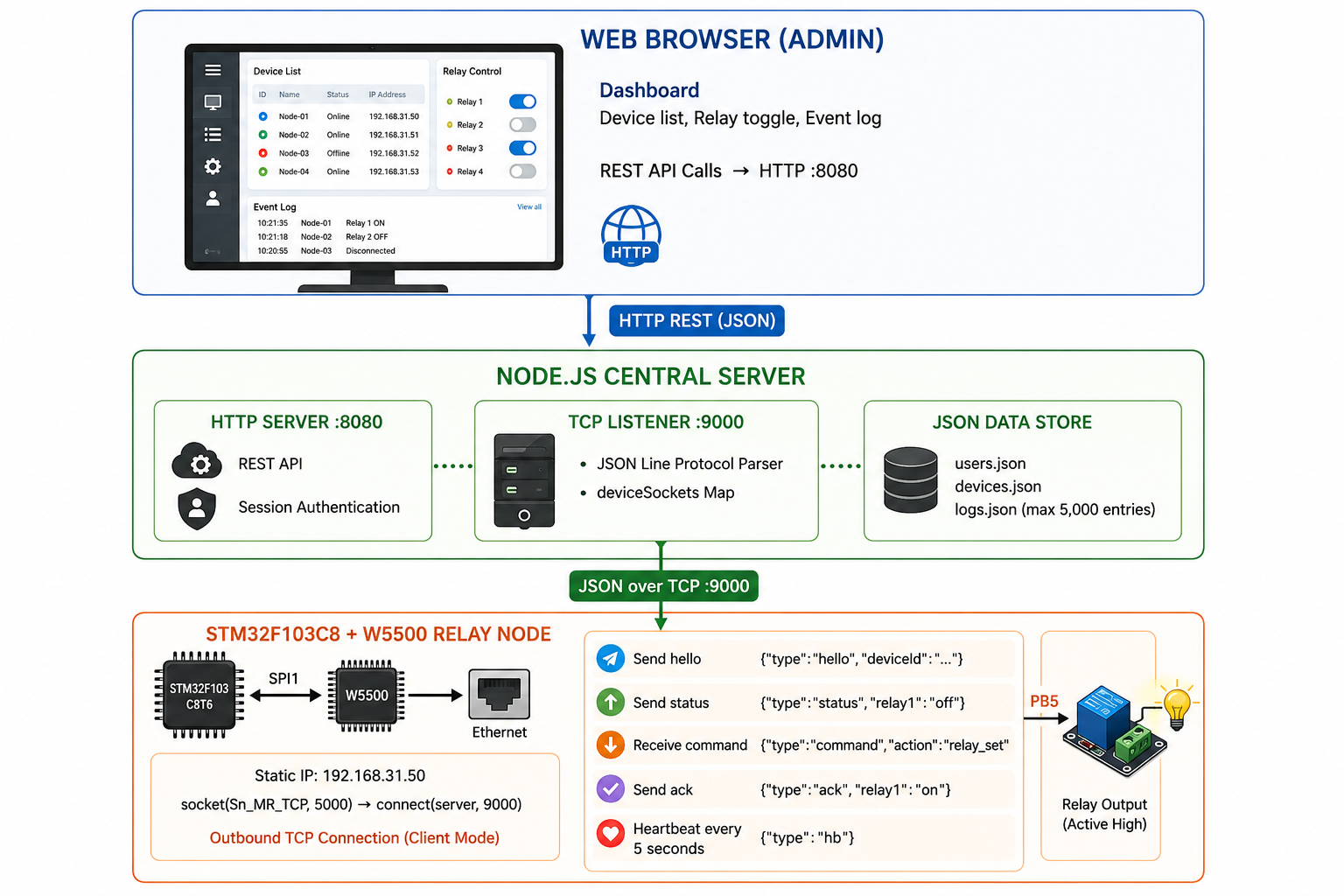
04 — Why W5500?
🔷 TOE TCP Socket Mode — Client-Initiated Persistent Connection
This project uses W5500's hardware TCP socket mode (Sn_MR_TCP) in an unusual pattern: the STM32 acts as the TCP client, initiating a persistent outbound connection to the Node.js server. This is the correct topology for a device behind NAT or in a network where inbound connections to the MCU are not desirable.
// From Core/Src/app_relay.c — confirmed socket(RELAY_SOCKET, Sn_MR_TCP, 5000, 0); // local port 5000 connect(RELAY_SOCKET, server_ip, SERVER_PORT); // connect to server :9000 send_hello(); // {"type":"hello","deviceId":"relay-f105-01"} send_status(); // {"type":"status","relay1":"off"}W5500's TOE handles TCP state, retransmission, and ACK entirely in hardware. The STM32 loop calls getSn_SR() to check connection health and recv() to get incoming commands — no TCP stack in firmware code at all.
🔷 PHY Link Monitoring — Hardware-Level Connectivity Awareness
The firmware polls wizphy_getphylink() during initialization and waits up to 2 seconds for the physical Ethernet link to come up before attempting any socket operations. This prevents connection attempts before the cable is live — a common failure mode in DIY projects that skip PHY state checking.
if (WaitForPhyLink(PHY_LINK_TIMEOUT_MS)) UART_Print("LAN OK\r\n"); else UART_Print("LAN FAIL\r\n");W5500's embedded PHY status register makes this one function call. On a raw MAC+external PHY design, this would require reading PHY registers over MDIO.
🔷 Auto-Reconnect Loop — Always-Connected Device Behavior
void socket_loop(void) { if (getSn_SR(RELAY_SOCKET) != SOCK_ESTABLISHED) { close(RELAY_SOCKET); HAL_Delay(1000); socket_connect(); // re-open Sn_MR_TCP socket and reconnect return; } // recv() → parse_cmd() }Every main loop iteration checks TCP connection health. Drop detected → reconnect within 1 second. The server-side socket.on("close") handler marks the device offline instantly. Together these form a closed-loop availability model with no manual intervention needed.
🔷 Static IP — Deterministic Network Identity
NETINFO_STATIC, IP 192.168.31.50. The device is reachable immediately after power-on. No DHCP boot delay, no address change surprises. For a relay node in a fixed-location deployment, static IP is always the right choice.
🔷 Verified Evidence ✅
socket(RELAY_SOCKET, Sn_MR_TCP, 5000, 0)confirmed inapp_relay.cconnect(),send(),recv(),getSn_SR()confirmed in application codewizchip_init(),wizchip_setnetinfo(),getVERSIONR()confirmed — chip version read at bootWaitForPhyLink()withwizphy_getphylink()confirmed — PHY link gate before socket- Serial debug log (
teraterm_logs.txt) included in repo — boot sequence captured on real hardware Server_based_Relay_controll.pdfincluded — project documentation
05 — Key Components
🌐 WIZnet W5500 — TCP TOE Mode (Sn_MR_TCP), Client Mode
Hardware TCP/IP offload over SPI1. The STM32 opens an outbound TCP connection to the Node.js server on port 9000. JSON messages flow over this persistent socket. No TCP stack in firmware — W5500 handles it in silicon.
🔧 STM32F103C8T6
72 MHz Cortex-M3. SPI1 drives W5500 (CS: PA4, RST: PB1). PB5 drives the relay output (active high). UART1 outputs debug messages to Tera Term. STM32CubeIDE project included (.ioc + .cproject).
🖥️ Node.js Backend (server.js)
Single-file server running both TCP listener (:9000, device side) and HTTP server (:8080, dashboard side). JSON line-protocol parsing, session-based authentication (PBKDF2 password hashing), JSON file datastore for users/devices/logs, REST API for dashboard control. No external database needed.
🌐 Web Admin Dashboard (frontend/)
Static HTML/CSS/JS dashboard. Login → overview summary → device list → relay toggle → per-device event log. Fully functional from any browser with no installation. Reads/writes via REST API to the Node.js backend.
06 — Application Scenarios
01. Smart Building Subsystem
Building automation engineers deploy STM32+W5500 relay nodes to control HVAC dampers, lighting circuits, or door locks. The central Node.js server aggregates all nodes into a unified dashboard, with timestamped logs satisfying basic audit requirements for facilities management.
02. Lab Equipment Power Management
A research lab installs one relay node per instrument rack. The admin dashboard shows which instruments are powered at a glance. Instruments can be toggled remotely without walking the lab. The event log provides a record of power cycling — useful for troubleshooting instrument failures correlated to power events.
03. Industrial Pilot Line Control
A small manufacturing line uses relay nodes to enable/disable conveyor motors or pneumatic valves from a central HMI browser interface. The heartbeat monitoring ensures the operator knows immediately if a node loses network connection — critical for safety-aware process control.
04. Home Automation Gateway
A maker installs relay nodes behind mains switches for lights, fans, or irrigation valves. The self-hosted Node.js server (Raspberry Pi or NAS) provides local-only control with no cloud dependency. The web dashboard is accessible from any device on the home network.
Conclusion
This project demonstrates that W5500's hardware TCP offload turns a bare STM32F103 into a fully managed IoT relay node — complete with JSON protocol, heartbeat monitoring, REST dashboard, and event logging.
- ✅ W5500 TCP TOE client mode confirmed —
socket(Sn_MR_TCP)+connect()inapp_relay.c - ✅ PHY link gate before socket —
wizphy_getphylink()polling confirmed - ✅ Auto-reconnect loop — connection health checked every main loop iteration
- ✅ JSON line-protocol bidirectional: hello / status / command / ack / heartbeat
- ✅ Node.js backend with authentication, REST API, and persistent event log (up to 5,000 entries)
- ✅ Browser-based admin dashboard — no client installation, works from any device
- ✅ Serial boot log (
teraterm_logs.txt) captured on real hardware - ✅ Full-stack in one repo: firmware + backend + frontend, 3-commit clean history
A relay, an STM32, and an Ethernet jack. This kind of project also uses W5500.
07 — Similar Projects on WIZnet Makers
Several projects on the platform address the same relay-over-Ethernet space.
Relay control via HTTP Rest Protocol (WIZnet official) demonstrates the concept using HTTP REST directly on the device. Simpler topology — no central server, browser talks directly to the MCU. → https://maker.wiznet.io/WIZnet/projects/relay-control-via-http-rest-protocol/
ESP32 (38-pin) + W5500: Offline LAN Relay Control with a Simple Web Server (sophia, 2026) uses ESP32+W5500 with an embedded web server — no separate backend server, browser hits the MCU directly. → https://maker.wiznet.io/sophia/projects/esp32-38-pin-w5500-offline-lan-relay-control-with-a-simple-web-server/
8 Channel Ethernet Relay Controller (Alan, 2025) scales up to 8 channels with PoE support — hardware-focused, no software dashboard. → https://maker.wiznet.io/Alan/projects/8-channel-ethernet-relay-controller-support-poe-and-usb/
| This Project | HTTP REST (WIZnet) | ESP32 Web Server | 8-Ch PoE Controller | |
|---|---|---|---|---|
| MCU | STM32F103 | — | ESP32 | — |
| W5500 role | TCP KM channel | HTTP server | On-board | On-board |
| Protocol | JSON over TCP | HTTP REST | HTTP (embedded) | — |
| Central server | ✅ Node.js | ❌ | ❌ | ❌ |
| Web dashboard | ✅ separate | ✅ (on MCU) | ✅ (on MCU) | ❌ |
| Auth + logging | ✅ | ❌ | ❌ | ❌ |
| Relay channels | 1 | varies | varies | 8 |
| Heartbeat / reconnect | ✅ | ❌ | ❌ | ❌ |
The key differentiator of this project is the centralized server architecture with authentication and logging — the only one in this group that treats the relay node as a managed device rather than a standalone controller. The trade-off is deployment complexity: Node.js backend must run separately. The insight is that as relay deployments grow beyond one or two nodes, centralized management becomes essential — and this project is the only one in the ecosystem already built for that.
Q&A
Q: Why does the STM32 connect outward to the server rather than the server connecting to the STM32? A: Client-initiated TCP is the correct model for devices behind NAT or on dynamic IPs. The device always knows the server's fixed IP; the server never needs to know the device's IP in advance. The hello message carries the device ID, letting the server register any device that connects.
Q: Why JSON over raw TCP rather than HTTP or MQTT? A: JSON over newline-delimited TCP is the lightest full-featured option for an STM32F103 with 64KB flash. HTTP adds request/response framing overhead; MQTT requires a broker. The Node.js server can parse newline-delimited JSON with three lines of code. For a single-channel prototype, this is the right trade-off.
Q: Can the system scale to multiple relay nodes? A: Yes by design. The deviceSockets Map and devices.json datastore on the server side are keyed by deviceId. Each firmware node just needs a unique DEVICE_ID string and the same server IP. The dashboard automatically lists all connected devices.
서버 기반 릴레이 제어 시스템 — 웹 대시보드를 갖춘 산업급 원격 스위칭
#릴레이제어 #IoT #스마트빌딩 #TOE-TCP #STM32 #W5500 #Node.js #웹대시보드 #JSON-over-TCP #원격제어
📚 개인 취미/학습 프로젝트 — STM32F103 + W5500 펌웨어 + Node.js 백엔드 + 웹 대시보드 풀스택 STM32F103C8 펌웨어 확인 완료;
app_relay.c에서 TCP 소켓 모드 검증됨
01 — 이 프로젝트는 무엇인가?
릴레이를 원격으로 켜고 끄는 것은 단순해 보인다 — 신뢰성, 감사 추적, 브라우저 어디서나 접근이 필요할 때까지는. 대부분의 DIY 릴레이 솔루션은 "UDP 패킷 하나 보내고 핀 토글"에서 멈춘다. 응답 확인도 없고, 누가 언제 무엇을 켰는지 기록도 없으며, 대시보드에서 현재 상태를 볼 방법도 없다.
이 프로젝트는 풀스택을 제공한다: STM32F103 펌웨어 노드가 W5500 이더넷을 통해 중앙 Node.js TCP 서버에 접속하고, JSON 명령을 수신하고, 물리 릴레이를 제어하고, 확인 응답을 돌려보낸다. Node.js 백엔드는 디바이스 상태를 저장하고, 타임스탬프가 찍힌 이벤트 로그를 기록하며, 브라우저 기반 관리 대시보드에 REST 엔드포인트를 제공한다. 결과물은 취미 가젯보다 관리형 IoT 디바이스에 가깝다 — 하트비트 모니터링, 인증, 실시간 감사 로그까지.
02 — 왜 네트워크 릴레이 제어인가?
🔷 "스마트"와 "관리됨"의 간극
소비자용 스마트 플러그는 벤더가 서비스를 종료하면 사라지는 독점 클라우드 API를 사용하고, 로컬 전용 동작을 막으며, 감사 로그를 제공하지 않는다. 제대로 된 관리 기능을 갖춘 산업용 릴레이 컨트롤러는 소규모 배포에 과하게 복잡하고 비싸다. 이 프로젝트는 그 중간에 위치한다: 완전 로컬, 완전 오픈, REST 접근 가능, 로그 보존 — 독점 클라우드 의존 없이.
🔷 TCP + 하트비트를 통한 신뢰성
시스템은 5초 하트비트({"type":"hb"})와 함께 영속 TCP 연결을 사용한다. 연결이 끊기면 펌웨어가 SOCK_ESTABLISHED 손실을 감지하고 자동으로 재접속한다. 서버는 소켓 종료 시 디바이스를 즉시 online: false로 표시한다. 이 폐루프 가용성 모델은 대시보드가 항상 실제 디바이스 상태를 반영하도록 보장한다.
🔷 단일 저장소의 풀스택
펌웨어(C/STM32), 백엔드(Node.js), 프론트엔드(HTML/CSS/JS)가 명확한 분리 구조로 하나의 저장소에 공존한다. 개발자 누구든 클론하고 IP 주소 두 개를 설정하면 몇 분 안에 엔드-투-엔드로 동작하는 시스템을 얻을 수 있다.
03 — 시스템 아키텍처
04 — 왜 W5500인가?
🔷 TOE TCP 소켓 모드 — 클라이언트 개시 영속 연결
이 프로젝트는 W5500의 **하드웨어 TCP 소켓 모드(Sn_MR_TCP)**를 독특한 패턴으로 사용한다: STM32가 TCP 클라이언트로서 Node.js 서버에 아웃바운드 연결을 개시한다. NAT 뒤에 있는 디바이스나 인바운드 연결이 바람직하지 않은 네트워크에서 올바른 토폴로지다.
// Core/Src/app_relay.c 에서 확인 socket(RELAY_SOCKET, Sn_MR_TCP, 5000, 0); // 로컬 포트 5000 connect(RELAY_SOCKET, server_ip, SERVER_PORT); // 서버 :9000으로 연결 send_hello(); // {"type":"hello","deviceId":"relay-f105-01"} send_status(); // {"type":"status","relay1":"off"}W5500의 TOE가 TCP 상태, 재전송, ACK를 하드웨어에서 전부 처리한다. STM32 루프는 getSn_SR()로 연결 상태를 확인하고 recv()로 명령을 수신할 뿐이다 — 펌웨어 코드에 TCP 스택이 전혀 없다.
🔷 PHY 링크 모니터링 — 하드웨어 레벨 연결 인식
펌웨어는 초기화 중 wizphy_getphylink()를 폴링해 소켓 동작 시도 전 최대 2초간 물리 이더넷 링크가 올라오기를 기다린다. 케이블이 연결되기 전에 소켓 동작을 시도하는 DIY 프로젝트의 흔한 실패 모드를 방지한다. W5500의 내장 PHY 상태 레지스터가 이를 함수 호출 하나로 가능하게 한다.
🔷 자동 재접속 루프 — 항상 연결된 디바이스 동작
메인 루프 매 반복마다 TCP 연결 상태를 확인한다. 연결 끊김 감지 → 1초 내 재접속. 서버 측 socket.on("close") 핸들러가 디바이스를 즉시 오프라인으로 표시한다. 이 두 가지가 합쳐져 수동 개입 없는 폐루프 가용성 모델을 형성한다.
🔷 Static IP — 결정론적 네트워크 신원
NETINFO_STATIC, IP 192.168.31.50. 전원 투입 직후 즉시 도달 가능. DHCP 부팅 지연 없음, 주소 변경 없음. 고정 위치 배포의 릴레이 노드에서 항상 올바른 선택이다.
🔷 검증된 증거 ✅
socket(RELAY_SOCKET, Sn_MR_TCP, 5000, 0)—app_relay.c에서 직접 확인connect(),send(),recv(),getSn_SR()— 애플리케이션 코드에서 확인wizchip_init(),wizchip_setnetinfo(),getVERSIONR()— 부팅 시 칩 버전 읽기 확인WaitForPhyLink()와wizphy_getphylink()— 소켓 전 PHY 링크 게이트 확인teraterm_logs.txt— 실제 하드웨어 부팅 시퀀스 시리얼 로그 저장소에 포함Server_based_Relay_controll.pdf— 프로젝트 문서 포함
05 — 핵심 컴포넌트
🌐 WIZnet W5500 — TCP TOE 모드 (Sn_MR_TCP), 클라이언트 모드
SPI1 버스의 하드웨어 오프로드 TCP/IP. STM32가 서버 포트 9000으로 아웃바운드 TCP 연결을 개시. JSON 메시지가 이 영속 소켓으로 흐름. 펌웨어에 TCP 스택 없음 — W5500이 실리콘에서 처리.
🔧 STM32F103C8T6
72 MHz Cortex-M3. SPI1이 W5500 구동 (CS: PA4, RST: PB1). PB5가 릴레이 출력 구동 (Active High). UART1이 Tera Term 디버그 출력. STM32CubeIDE 프로젝트 포함 (.ioc + .cproject).
🖥️ Node.js 백엔드 (server.js)
TCP 리스너(:9000, 디바이스 측)와 HTTP 서버(:8080, 대시보드 측)를 모두 실행하는 단일 파일 서버. JSON 라인 프로토콜 파싱, 세션 기반 인증(PBKDF2 패스워드 해싱), 사용자/디바이스/로그를 위한 JSON 파일 데이터스토어, 대시보드 제어용 REST API. 외부 데이터베이스 불필요.
🌐 웹 관리 대시보드 (frontend/)
정적 HTML/CSS/JS 대시보드. 로그인 → 개요 요약 → 디바이스 목록 → 릴레이 토글 → 디바이스별 이벤트 로그. 설치 없이 어느 브라우저에서나 완전 동작. Node.js 백엔드 REST API로 읽기/쓰기.
06 — 활용 시나리오
01. 스마트 빌딩 서브시스템
빌딩 자동화 엔지니어가 HVAC 댐퍼, 조명 회로, 도어락 제어를 위해 STM32+W5500 릴레이 노드를 배포한다. 중앙 Node.js 서버가 모든 노드를 통합 대시보드로 집계하며, 타임스탬프 로그가 시설 관리의 기본 감사 요건을 충족한다.
02. 연구실 장비 전원 관리
연구실이 장비 랙마다 릴레이 노드를 설치한다. 관리자 대시보드가 어떤 장비에 전원이 들어와 있는지 한눈에 보여준다. 장비를 물리적으로 이동하지 않고 원격으로 전원을 토글할 수 있다. 이벤트 로그가 전원 사이클링 기록을 제공한다.
03. 산업용 파일럿 라인 제어
소규모 제조 라인이 릴레이 노드를 사용해 컨베이어 모터나 공압 밸브를 중앙 HMI 브라우저 인터페이스에서 활성화/비활성화한다. 하트비트 모니터링이 노드가 네트워크 연결을 잃으면 운영자에게 즉시 알린다.
04. 홈 오토메이션 게이트웨이
메이커가 조명, 선풍기, 관개 밸브의 전원 스위치 뒤에 릴레이 노드를 설치한다. 자체 호스팅 Node.js 서버(라즈베리 파이 또는 NAS)가 클라우드 의존 없이 로컬 전용 제어를 제공한다.
결론
이 프로젝트는 W5500의 하드웨어 TCP 오프로드가 맨 STM32F103을 JSON 프로토콜, 하트비트 모니터링, REST 대시보드, 이벤트 로깅을 갖춘 완전 관리형 IoT 릴레이 노드로 전환시킨다는 것을 보여준다.
- ✅ W5500 TCP TOE 클라이언트 모드 확인 —
app_relay.c에서socket(Sn_MR_TCP)+connect() - ✅ 소켓 전 PHY 링크 게이트 —
wizphy_getphylink()폴링 확인 - ✅ 자동 재접속 루프 — 메인 루프 매 반복 연결 상태 확인
- ✅ JSON 라인 프로토콜 양방향: hello / status / command / ack / heartbeat
- ✅ 인증, REST API, 영속 이벤트 로그(최대 5,000건)를 갖춘 Node.js 백엔드
- ✅ 브라우저 기반 관리 대시보드 — 클라이언트 설치 불필요
- ✅ 실제 하드웨어에서 캡처한 시리얼 부팅 로그(
teraterm_logs.txt) 포함 - ✅ 단일 저장소 풀스택: 펌웨어 + 백엔드 + 프론트엔드, 3커밋 깔끔한 이력
릴레이 하나, STM32, 이더넷 잭 하나. 이런 종류의 프로젝트도 W5500을 사용한다.
07 — WIZnet Makers 유사 프로젝트
플랫폼에서 같은 릴레이-over-이더넷 공간을 다루는 프로젝트들이 다수 존재한다.
Relay control via HTTP Rest Protocol (WIZnet 공식)은 HTTP REST를 디바이스에서 직접 처리한다. 더 단순한 토폴로지 — 중앙 서버 없이 브라우저가 MCU에 직접 통신. → https://maker.wiznet.io/WIZnet/projects/relay-control-via-http-rest-protocol/
ESP32 (38-pin) + W5500: Offline LAN Relay Control with a Simple Web Server (sophia, 2026)는 ESP32+W5500과 내장 웹 서버를 사용한다 — 별도 백엔드 서버 없이 브라우저가 MCU에 직접 접속. → https://maker.wiznet.io/sophia/projects/esp32-38-pin-w5500-offline-lan-relay-control-with-a-simple-web-server/
8 Channel Ethernet Relay Controller (Alan, 2025)는 PoE 지원으로 8채널까지 확장한다 — 하드웨어 중심, 소프트웨어 대시보드 없음. → https://maker.wiznet.io/Alan/projects/8-channel-ethernet-relay-controller-support-poe-and-usb/
| 이 프로젝트 | HTTP REST | ESP32 웹 서버 | 8채널 PoE | |
|---|---|---|---|---|
| MCU | STM32F103 | — | ESP32 | — |
| W5500 역할 | TCP 제어 채널 | HTTP 서버 | 온보드 | 온보드 |
| 프로토콜 | JSON over TCP | HTTP REST | HTTP (내장) | — |
| 중앙 서버 | ✅ Node.js | ❌ | ❌ | ❌ |
| 웹 대시보드 | ✅ 분리형 | ✅ (MCU 내) | ✅ (MCU 내) | ❌ |
| 인증 + 로깅 | ✅ | ❌ | ❌ | ❌ |
| 릴레이 채널 | 1 | 다양 | 다양 | 8 |
| 하트비트/재접속 | ✅ | ❌ | ❌ | ❌ |
이 프로젝트의 핵심 차별점은 인증과 로깅을 갖춘 중앙화 서버 아키텍처 — 릴레이 노드를 독립형 컨트롤러가 아닌 관리형 디바이스로 취급하는 유일한 프로젝트다. 트레이드오프는 배포 복잡성: Node.js 백엔드가 별도로 실행되어야 한다. 인사이트는 릴레이 배포가 노드 한두 개를 넘어 확장되면 중앙화 관리가 필수가 된다는 것이고, 이 프로젝트는 이미 그것을 위해 설계된 생태계 내 유일한 존재다.
Q&A
Q: STM32가 서버에 아웃바운드로 연결하는 이유는? A: 클라이언트 개시 TCP가 NAT 뒤에 있거나 동적 IP를 가진 디바이스에 올바른 모델이다. 디바이스는 항상 서버의 고정 IP를 알고 있고, 서버는 디바이스 IP를 미리 알 필요가 없다. hello 메시지가 디바이스 ID를 전달해 서버가 접속하는 모든 디바이스를 등록할 수 있게 한다.
Q: HTTP나 MQTT 대신 TCP 위 JSON을 사용한 이유는? A: 뉴라인 구분 JSON over TCP는 64KB 플래시를 가진 STM32F103에서 가장 가벼운 완전 기능 옵션이다. HTTP는 요청/응답 프레이밍 오버헤드를 추가하고, MQTT는 브로커가 필요하다. Node.js 서버는 세 줄의 코드로 뉴라인 구분 JSON을 파싱할 수 있다.
Q: 여러 릴레이 노드로 확장될 수 있나? A: 설계상 가능하다. 서버 측 deviceSockets Map과 devices.json 데이터스토어는 deviceId를 키로 한다. 각 펌웨어 노드는 고유한 DEVICE_ID 문자열과 동일한 서버 IP만 있으면 된다. 대시보드가 연결된 모든 디바이스를 자동으로 나열한다.