



Open source nanovoltmeter
Open source nanovoltmeter
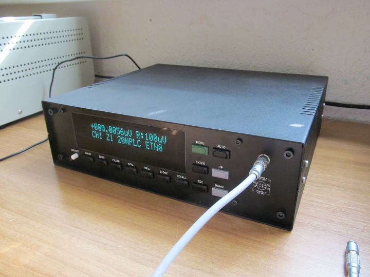
Open Source Nanovoltmeter — When a $5,000 Bench Instrument Becomes a DIY Project
#Nanovoltmeter #SCPI #W5500 #TCP-TOE #STM32 #TestAndMeasurement #OpenHardware #KiCad #FPGA #Precision
📚 Advanced open-source hardware project — precision scientific instrument built from scratch, entered in the xDevs nanovolt challenge (2021–2022) ✅ Fully documented: complete KiCad PCB files, STM32 firmware with W5500 ioLibrary, FPGA Verilog, gerbers, BOMs, measurement data — all verified in repository
01 — What is this project?
A nanovoltmeter is a precision DC voltmeter capable of resolving voltages down to the nanovolt range — a billionth of a volt. Commercial instruments in this class, such as the Keithley 2182A or Keysight 34420A, routinely cost $4,000–$6,000 and are found in standards laboratories, semiconductor characterization setups, and cryogenic research. What makes them hard to build is not the voltage measurement itself, but the compound problem of eliminating every source of thermal electromotive force (TEMF), the tiny voltages generated by dissimilar metals at junctions when temperature gradients exist — errors that dwarf the signal being measured.
In 2021, TiN from the xdevs metrology community launched the "nanovolt challenge": build an open-source nanovoltmeter with performance comparable to commercial instruments, in 256 days, on a DIY budget. Jaromir Sukuba accepted. The result is this project: a full 6.5-digit nanovoltmeter with noise below 25 nV peak-to-peak on the 100 µV range, two galvanically isolated input channels, autocalibration, SCPI remote control via Ethernet, and a complete open-source hardware package — PCB design files, firmware, FPGA code, gerbers, BOMs, mechanical 3D-print files, and measurement data.
The instrument resolves voltages from ±100 µV to ±10 V across six ranges, all from a 12 W power budget.
02 — Why This Architecture?
🔷 100 MCP6V51 op-amps in parallel — the unconventional LNA
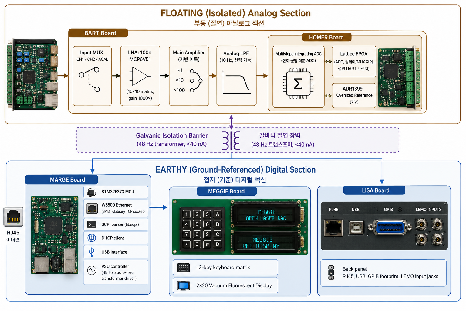
The core measurement challenge is the low-noise amplifier (LNA) on the analog front end. Reducing amplifier noise by paralleling N identical devices improves noise by √N. Instead of exotic low-noise JFETs (expensive, high parameter spread), the design arrays 100 Microchip MCP6V51 autozero/chopper op-amps in a 10×10 matrix: 10 groups of 10 in a non-inverting first stage, then 10 summing second-stage amplifiers, and finally a single output stage — 1000× gain overall. The MCP6V51's autozero architecture eliminates DC offset drift, and the array averaging suppresses noise to below 30 nV p-p in 10 Hz bandwidth.
🔷 Galvanic isolation barrier — the floating analog front end
Any nanovoltmeter must separate its analog input terminals from mains-referenced ground. Even tiny leakage currents (hundreds of nanoamps) flowing through ground paths create millivolt-level errors across measurement resistances. The design places the entire analog section — LNA, ADC, FPGA, reference — behind a galvanic isolation barrier. Power crosses the barrier via a custom audio-frequency transformer driven by a TPS3116 class-D amplifier at 48 Hz (chosen to balance isolation leakage and efficiency). Measured common-mode leakage: below 40 nA peak-to-peak.
🔷 Custom multislope integrating ADC — built into the FPGA
Rather than using a commercial sigma-delta ADC, the design implements a multislope integrating charge-balance ADC inside the Lattice FPGA on the Homer board. This topology provides excellent linearity (INL within 6.5-digit bounds, verified against a Solartron 7081 reference) and inherent rejection of power-line interference. ADC integration time is configurable in NPLC (power-line cycle) multiples: 1, 2, 5, 10, or 20 NPLC. At 20 NPLC (400 ms integration), normal-mode rejection of 50/60 Hz is approximately −90 dB.
🔷 Autocalibration — one reference value to rule all ranges
The instrument requires only the 7 V reference voltage (ADR1399 ovenized reference) to be entered once via SCPI. From that single anchor, an internal autocalibration routine derives all six range gain coefficients automatically, compensating for resistor drift and temperature effects without manual adjustment at each range.
03 — System Architecture
04 — Why W5500?
🔷 TCP socket mode (TOE) via WIZnet ioLibrary — Sn_MR_TCP
The W5500 is used in TCP server socket mode (Sn_MR_TCP) through the standard WIZnet ioLibrary (wizchip_init, socket, listen, accept, recv, send). The STM32F373 on the Marge board initializes the W5500 over SPI3, registers CS/SPI callbacks, and then runs a TCP server that accepts SCPI command strings from any connected Ethernet client. The firmware's DHCP client obtains an IP address automatically; the front panel display shows ETH1 when a lease is active.
The W5500's hardwired TCP/IP stack handles all connection state management, retransmission, and flow control in silicon. The STM32 only exchanges completed application-layer data — SCPI command strings in, measurement values out. For a precision instrument where the MCU's primary job is orchestrating ADC timing, relay switching, autocalibration, and display updates, offloading the entire TCP/IP stack to the W5500 is the right architectural choice.
🔷 SCPI over TCP — instrument-grade remote control
SCPI (Standard Commands for Programmable Instruments) is the IEEE 488.2-based command language used by every major bench instrument vendor (Keithley, Keysight, Rohde & Schwarz). By implementing SCPI over TCP/IP with the W5500, this nanovoltmeter integrates directly into any automated test environment — Python scripts using pyvisa-py, LabVIEW VISA, MATLAB Instrument Control Toolbox, or any SPCI-capable software can discover, configure, and read the instrument over Ethernet without any custom driver.
Supported commands include MEASure:VOLTage?, SENSe:RANGe, SENSe:NPLC, SENSe:AFILter, SENSe:DFILter, CALibration:ACAL, *IDN?, *RST, and more — a complete implementation verified in the telnet.c source (socket(sn, Sn_MR_TCP, port, 0x00) → listen → recv/send).
🔷 Hardware-level SPI init — direct register access, no HAL
The W5500 SPI interface is initialized entirely via direct STM32 register writes in hw.c — no STM32 HAL, no CubeMX abstraction. SPI3 is configured manually (SPI_CR1_MSTR, SPI_CR1_SPE, burst callback registration), and the ioLibrary's reg_wizchip_cs_cbfunc / reg_wizchip_spi_cbfunc / reg_wizchip_spiburst_cbfunc hooks are wired directly to GPIO and SPI3 routines. This keeps the firmware footprint minimal and the timing deterministic — important in a measurement instrument where latency on the MCU should not interfere with ADC timing.
🔷 Verified in hardware ✅
The README documents performance results measured against reference instruments: noise < 25 nV p-p at 100 µV range, INL verified against a Solartron 7081, step response logged against a Keithley 260 voltage source. The Ethernet connection is explicitly confirmed in the display readout (ETH1 indicator) and the SCPI command set is documented as operational.
05 — Key Components
🌐 WIZnet W5500 — TCP Socket Mode (Sn_MR_TCP) via ioLibrary
- SPI3, STM32F373 (direct register init, no HAL)
- TCP server for SCPI command reception
- DHCP client for automatic IP assignment
- ETH status displayed on VFD front panel
🧠 STM32F373VBTx (Marge board)
- Cortex-M4F with hardware FPU — floating-point SCPI value formatting
- Coordinates: SCPI parsing (libscpi), relay switching, display, keyboard, PSU startup sequencing
- UART bridge to FPGA over isolation barrier
🔬 Lattice FPGA (Homer board, isolated side)
- Implements multislope integrating ADC state machine
- Controls relay MUX, reference switching, analog filter
- UART isolated serial link to STM32
📐 100× MCP6V51 Low-Noise Amplifier (Bart board)
- 10×10 parallel autozero op-amp array, gain 1000×
- Noise: < 30 nV p-p in 10 Hz bandwidth (verified)
- Autozero/chopper topology eliminates DC offset drift
⚡ ADR1399 Ovenized Reference (Homer board)
- 7 V ovenized reference — the single calibration anchor for all ranges
- Temperature-stabilized for long-term stability
🖥️ 2×20 Vacuum Fluorescent Display + 13-key Keyboard (Meggie/front panel)
- Full local operation — no external equipment required
- Displays measured value, range, NPLC, filter state, ETH status
🏗️ 5-PCB modular design (KiCad, Modushop enclosure)
- Bart (LNA + MUX) / Homer (FPGA + ADC + reference) / Lisa (back panel) / Meggie (keyboard) / Marge (PSU + MCU + W5500)
- Full KiCad design files, gerbers, ibom, BOM — all open
06 — Application Scenarios
01. Automated Precision Measurement in a Lab Setup
Connect the nanovoltmeter to a LAN, issue MEASure:VOLTage? from a Python script via pyvisa-py, and log 6.5-digit readings at 1 NPLC for high-speed data collection or at 20 NPLC for maximum rejection of power-line noise. No proprietary driver needed — SCPI over TCP is the universal instrument control language.
02. Differential Resistance Measurement
Combined with a stable current source, the nanovoltmeter measures the voltage drop across a low-value resistor (milliohm range) or resolves small resistance changes in cryogenic or strain-gauge setups. The 100 µV range with < 25 nV p-p noise enables 4-wire resistance measurements that rival commercial instruments.
03. Voltage Reference Characterization
The autozero function and 10-second averaging at 20 NPLC allow characterization of voltage reference ICs over temperature — measuring drift in the single-nanovolt range. The isolated front end prevents ground loop injection from the reference under test.
04. Educational Platform for Precision Analog Design
Every section of the design — parallel op-amp LNA theory, multislope ADC architecture, isolation barrier design, TEMF mitigation, SCPI protocol — is documented in the README with performance verification data. The full open-source package (KiCad, Verilog, STM32 firmware) is a rare public resource for engineers learning precision instrument design.
Conclusion
This project delivers 6.5-digit nanovoltmeter performance — the domain of $5,000 commercial instruments — from a $400 open-source hardware platform, with full SCPI remote control via W5500 Ethernet.
- ✅ Noise < 25 nV peak-to-peak at 100 µV range (verified against reference instruments)
- ✅ 6.5-digit resolution, 6 ranges: ±100 µV to ±10 V
- ✅ 100× parallel MCP6V51 LNA — unconventional but effective noise reduction
- ✅ Galvanic isolation: < 40 nA common-mode leakage across isolation barrier
- ✅ Custom FPGA multislope integrating ADC — no commercial ADC black box
- ✅ SCPI over TCP via W5500 — full lab automation compatibility
- ✅ ADR1399 ovenized reference with single-parameter autocalibration
- ✅ Complete open-source package: KiCad PCBs, STM32 firmware, FPGA Verilog, gerbers, BOMs, STL files, measurement data
- ✅ Total cost: ~€400 in components
Precision scientific instrumentation is also the kind of project that uses W5500.
07 — Similar Projects on WIZnet Makers
Two other projects on the platform use W5500 to bring SCPI or Ethernet remote control to bench instruments:
| Project | WIZnet Chip | Protocol | Instrument Type | Notes |
|---|---|---|---|---|
| PIC18F56K42_W5500_SCPI | W5500 | SCPI over TCP | Generic SCPI framework | PIC18F + W5500, reusable template |
| DIY Programmable Bench Power Supply (SCPI) | W5500 | SCPI over TCP | Bench power supply | Programmable PSU with SCPI control |
All three projects use W5500 in TCP socket mode for SCPI command delivery — the same underlying pattern. What distinguishes the nanovoltmeter is the measurement domain: where the power supply and generic SCPI framework target output control, the nanovoltmeter targets sub-100 nV input resolution — a fundamentally different and more demanding signal chain. The W5500 plays the same role in each: a hardwired TCP/IP interface that lets the MCU ignore protocol overhead and focus on its core job.
Q&A
Q: What socket mode does the W5500 use, and why TCP rather than UDP? A: The firmware uses socket(sn, Sn_MR_TCP, port, 0x00) followed by listen() — TCP server mode. SCPI over TCP is the standard for lab instrument remote control because TCP guarantees ordered, reliable delivery of command strings. A dropped or reordered UDP packet would corrupt a SCPI command sequence, potentially triggering the wrong measurement range or calibration operation — unacceptable in a precision instrument.
Q: Can the nanovoltmeter be controlled without Ethernet? A: Yes. The instrument is fully standalone via the 13-key front panel and VFD display. Ethernet is an additive remote control interface. The firmware also includes a USB interface on the Marge board for local PC connection without a network.
Q: How does the isolation barrier affect Ethernet connectivity? A: The W5500 and STM32 reside on the earthy (ground-referenced) Marge board, outside the isolation barrier. Ethernet connects to ground-referenced circuitry only. The galvanic isolation separates the input measurement terminals (Bart/Homer boards) from all digital I/O including Ethernet — this is the standard architecture for all precision instruments with isolated inputs.
Original Link: https://github.com/jaromir-sukuba/nvm
오픈소스 나노볼트미터 — $5,000짜리 계측기를 DIY로
#나노볼트미터 #SCPI #W5500 #TCP-TOE #STM32 #계측 #오픈하드웨어 #KiCad #FPGA #정밀측정
📚 고급 오픈소스 하드웨어 프로젝트 — xDevs 나노볼트 챌린지(2021~2022) 출품작, 정밀 과학 계측기를 처음부터 직접 설계 ✅ 완전히 문서화됨: KiCad PCB 파일, W5500 ioLibrary 적용 STM32 펌웨어, FPGA Verilog, 거버, BOM, 측정 데이터 — 저장소에서 직접 검증
01 — 이 프로젝트는 무엇인가?
나노볼트미터는 나노볼트(10억 분의 1볼트) 단위의 미세 DC 전압을 분해할 수 있는 정밀 전압계다. Keithley 2182A나 Keysight 34420A 같은 상용 제품은 $4,000~$6,000에 달하며, 표준 연구소·반도체 특성 측정·극저온 연구에 사용된다. 이 장비를 만들기 어려운 이유는 전압 측정 자체가 아니라, 온도 구배가 있을 때 이종 금속 접합부에서 발생하는 미세 전압인 열기전력(TEMF, Thermal Electromotive Force)을 모든 경로에서 제거해야 한다는 복합적인 문제 때문이다.
2021년, xdevs 계측 커뮤니티의 TiN이 "나노볼트 챌린지"를 시작했다: 256일 안에, DIY 예산으로, 상용 계측기와 견줄 만한 성능의 오픈소스 나노볼트미터를 만들어라. Jaromir Sukuba가 이에 응했다. 결과물이 바로 이 프로젝트다: 100 µV 레인지에서 노이즈 25 nV peak-to-peak 이하, 갈바닉 절연 2채널 입력, 자동 캘리브레이션, Ethernet SCPI 원격 제어를 갖춘 6.5자리 나노볼트미터 — PCB 설계 파일, 펌웨어, FPGA 코드, 거버, BOM, 기구 3D 프린트 파일, 측정 데이터까지 모두 공개된 완전한 오픈소스 하드웨어 패키지.
12 W 소비 전력으로 ±100 µV~±10 V, 6단계 레인지를 모두 커버한다.
02 — 이 아키텍처를 선택한 이유
🔷 MCP6V51 100개 병렬 — 비관습적 저노이즈 증폭기
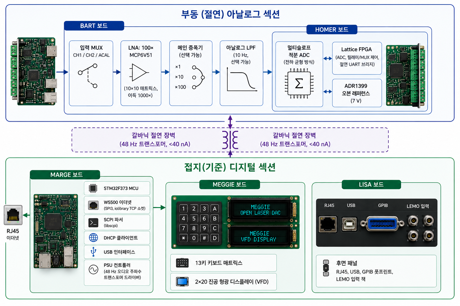
아날로그 프런트엔드의 핵심은 저노이즈 증폭기(LNA)다. 동일 소자를 N개 병렬로 연결하면 노이즈가 √N 비율로 감소한다. 고가의 저노이즈 JFET 대신, 이 설계는 Microchip MCP6V51 오토제로/초퍼 op-amp 100개를 10×10 매트릭스로 배열한다: 10개 묶음 × 10개의 1단 비반전 증폭기 → 10개의 2단 합산 증폭기 → 최종 출력단, 전체 이득 1,000배. MCP6V51의 오토제로 구조가 DC 오프셋 드리프트를 제거하고, 배열 평균화가 10 Hz 대역폭에서 30 nV p-p 이하의 노이즈를 실현한다.
🔷 갈바닉 절연 — 부동 아날로그 프런트엔드
나노볼트미터는 아날로그 입력 단자를 반드시 접지 기준에서 분리해야 한다. 수백 나노암페어의 누설 전류도 측정 저항 양단에 밀리볼트급 오차를 유발한다. 이 설계는 LNA·ADC·FPGA·기준 전압원을 포함한 전체 아날로그 섹션을 갈바닉 절연 배리어 너머에 배치한다. 전력은 TPS3116 D급 증폭기로 구동하는 커스텀 오디오 주파수 변압기(48 Hz, 누설과 효율의 균형점)를 통해 배리어를 넘는다. 측정된 공통 모드 누설: 40 nA peak-to-peak 이하.
🔷 커스텀 멀티슬로프 적분형 ADC — FPGA 내부에 직접 구현
상용 시그마-델타 ADC 대신, Homer 보드의 Lattice FPGA 내에 멀티슬로프 적분 전하균형 ADC를 직접 구현했다. 이 방식은 우수한 선형성(Solartron 7081 기준기 대비 6.5자리 INL 검증)과 전원 주파수 간섭의 내재적 제거를 제공한다. ADC 적분 시간은 NPLC(전원 주기 배수): 1·2·5·10·20 NPLC로 설정 가능하며, 20 NPLC(400 ms 적분)에서 50/60 Hz 정규 모드 제거비는 약 −90 dB다.
🔷 자동 캘리브레이션 — 기준 전압 하나로 전 레인지 자동 보정
계기는 7 V 기준 전압(ADR1399 오븐형 기준)을 SCPI로 한 번만 입력하면 된다. 내부 자동 캘리브레이션 루틴이 이 단일 값으로 6개 레인지의 모든 이득 계수를 자동으로 도출하며, 저항 드리프트와 온도 변화를 별도 조정 없이 보상한다.
03 — 시스템 아키텍처
04 — 왜 W5500인가?
🔷 TCP 소켓 모드 (Sn_MR_TCP) — WIZnet ioLibrary
W5500은 표준 WIZnet ioLibrary(wizchip_init, socket, listen, accept, recv, send)를 통해 **TCP 서버 소켓 모드(Sn_MR_TCP)**로 사용된다. Marge 보드의 STM32F373이 SPI3으로 W5500을 초기화하고, CS/SPI 콜백을 등록한 뒤 SCPI 명령 문자열을 수신하는 TCP 서버를 실행한다. DHCP 클라이언트가 IP를 자동으로 획득하며, 전면 패널 VFD에 ETH1으로 연결 상태를 표시한다.
W5500의 하드와이어드 TCP/IP 스택이 연결 상태 관리·재전송·흐름 제어를 실리콘에서 처리한다. STM32는 애플리케이션 레이어 데이터만 교환한다 — SCPI 명령 문자열 수신, 측정값 문자열 송신. ADC 타이밍·릴레이 전환·자동 캘리브레이션·디스플레이 갱신이 주업무인 정밀 계측기 MCU에게 TCP/IP 스택 전체를 W5500에 오프로드하는 것은 올바른 아키텍처 선택이다.
🔷 TCP SCPI — 계측기 등급 원격 제어
SCPI(Standard Commands for Programmable Instruments)는 Keithley·Keysight·R&S 등 모든 주요 계측기 제조사가 사용하는 IEEE 488.2 기반 명령 언어다. W5500으로 SCPI over TCP를 구현함으로써, 이 나노볼트미터는 별도 드라이버 없이 모든 자동화 테스트 환경과 통합된다 — Python pyvisa-py, LabVIEW VISA, MATLAB Instrument Control Toolbox에서 Ethernet으로 바로 제어 가능하다.
MEASure:VOLTage?, SENSe:RANGe, SENSe:NPLC, CALibration:ACAL, *IDN? 등 완전한 SCPI 명령셋이 telnet.c에서 socket(sn, Sn_MR_TCP, ...) → listen → recv/send 패턴으로 구현되어 있다.
🔷 직접 레지스터 접근 — HAL 없는 SPI 초기화
W5500 SPI 인터페이스는 hw.c에서 STM32 레지스터를 직접 조작해 초기화된다(SPI_CR1_MSTR, SPI_CR1_SPE 등). CubeMX 추상화 없이 GPIO와 SPI3 루틴을 ioLibrary 콜백에 직접 연결한다. 계측기에서 MCU 레이턴시가 ADC 타이밍을 방해해서는 안 되므로, 펌웨어 풋프린트를 최소화하고 타이밍을 결정론적으로 유지하는 이 방식이 적합하다.
🔷 실제 하드웨어에서 검증됨 ✅
README에 기준 계측기 대비 성능 결과가 문서화되어 있다: 100 µV 레인지 노이즈 < 25 nV p-p, Solartron 7081 대비 INL 검증, Keithley 260 전압 소스 대비 스텝 응답 로그. Ethernet 연결은 VFD 전면 패널의 ETH1 인디케이터로 명시적으로 확인된다.
05 — 핵심 컴포넌트
🌐 WIZnet W5500 — TCP 소켓 모드 (Sn_MR_TCP), ioLibrary
- SPI3, STM32F373 (직접 레지스터 초기화, HAL 없음)
- SCPI 명령 수신용 TCP 서버
- DHCP 클라이언트 (자동 IP 할당)
- ETH 상태 VFD 전면 패널에 표시
🧠 STM32F373VBTx (Marge 보드)
- Cortex-M4F (하드웨어 FPU — 부동소수점 SCPI 값 포매팅)
- SCPI 파싱(libscpi), 릴레이 전환, 디스플레이, 키보드, PSU 시퀀싱 담당
- 절연 배리어 너머 FPGA와 UART 브리지
🔬 Lattice FPGA (Homer 보드, 절연 측)
- 멀티슬로프 적분 ADC 상태 머신 구현
- 릴레이 MUX·기준 전환·아날로그 필터 제어
- STM32와 절연 직렬 링크(UART)
📐 MCP6V51 저노이즈 증폭기 100개 (Bart 보드)
- 10×10 병렬 오토제로 op-amp 배열, 이득 1,000×
- 노이즈: 10 Hz 대역폭에서 < 30 nV p-p (검증됨)
- 오토제로/초퍼 구조로 DC 오프셋 드리프트 제거
⚡ ADR1399 오븐형 기준 전압 (Homer 보드)
- 7 V 오븐형 기준 — 전 레인지 단일 캘리브레이션 앵커
- 장기 안정성을 위한 온도 안정화
🖥️ 2×20 진공 형광 디스플레이 + 13키 키보드
- 완전한 로컬 독립 동작 — 외부 장비 불필요
- 측정값, 레인지, NPLC, 필터 상태, ETH 상태 표시
🏗️ 5 PCB 모듈 설계 (KiCad, Modushop 엔클로저)
- Bart(LNA+MUX) / Homer(FPGA+ADC+기준) / Lisa(후면 패널) / Meggie(키보드) / Marge(PSU+MCU+W5500)
- KiCad 설계 파일, 거버, ibom, BOM 전량 공개
06 — 활용 시나리오
01. 실험실 자동화 정밀 측정
나노볼트미터를 LAN에 연결하고, Python 스크립트에서 pyvisa-py로 MEASure:VOLTage?를 발행해 6.5자리 측정값을 로깅한다. 별도 드라이버 불필요 — SCPI over TCP가 범용 계측기 제어 언어다.
02. 저저항 4선 측정
안정된 전류원과 결합하여 밀리옴 영역 저항이나 극저온·스트레인 게이지 설정에서의 소저항 변화를 분해한다. 100 µV 레인지의 < 25 nV p-p 노이즈가 상용 계측기와 견줄 4선 저항 측정을 가능하게 한다.
03. 전압 기준 IC 특성 측정
오토제로 기능과 20 NPLC 평균화로 온도에 따른 기준 전압 IC의 드리프트를 단일 나노볼트 분해능으로 측정한다. 절연 프런트엔드가 피측정 기준의 접지 루프 주입을 차단한다.
04. 정밀 아날로그 설계 교육 플랫폼
병렬 op-amp LNA 이론, 멀티슬로프 ADC 아키텍처, 절연 배리어 설계, TEMF 완화, SCPI 프로토콜 — 모든 섹션이 성능 검증 데이터와 함께 README에 문서화되어 있다. KiCad, Verilog, STM32 펌웨어 전체 공개는 정밀 계측기 설계를 학습하는 엔지니어에게 희귀한 공개 자료다.
Conclusion
이 프로젝트는 $5,000짜리 상용 계측기의 영역인 6.5자리 나노볼트미터 성능을, €400 오픈소스 하드웨어와 W5500 기반 SCPI Ethernet 원격 제어로 구현해냈다.
- ✅ 노이즈 < 25 nV peak-to-peak at 100 µV 레인지 (기준 계측기 대비 검증)
- ✅ 6.5자리 분해능, 6 레인지: ±100 µV~±10 V
- ✅ MCP6V51 100개 병렬 LNA — 비관습적이지만 검증된 노이즈 저감
- ✅ 갈바닉 절연: 절연 배리어 공통 모드 누설 < 40 nA
- ✅ FPGA 내부 커스텀 멀티슬로프 적분 ADC — 상용 ADC 블랙박스 없음
- ✅ W5500으로 SCPI over TCP — 완전한 랩 자동화 호환성
- ✅ ADR1399 오븐형 기준 + 단일 파라미터 자동 캘리브레이션
- ✅ 완전한 오픈소스: KiCad PCB, STM32 펌웨어, FPGA Verilog, 거버, BOM, STL, 측정 데이터
- ✅ 총 부품 비용 약 €400
정밀 과학 계측 또한 W5500을 사용하는 프로젝트다.
07 — WIZnet Makers의 유사 프로젝트
플랫폼에 SCPI over Ethernet 패턴을 공유하는 프로젝트가 두 개 있다:
| 프로젝트 | WIZnet 칩 | 프로토콜 | 계측기 종류 | 비고 |
|---|---|---|---|---|
| PIC18F56K42_W5500_SCPI | W5500 | SCPI over TCP | 범용 SCPI 프레임워크 | PIC18F + W5500, 재사용 가능 템플릿 |
| DIY 프로그래머블 벤치 파워서플라이 (SCPI) | W5500 | SCPI over TCP | 벤치 파워서플라이 | SCPI 제어 프로그래머블 PSU |
세 프로젝트 모두 W5500 TCP 소켓 모드로 SCPI 명령을 전달한다는 동일한 패턴을 사용한다. 나노볼트미터를 구분짓는 것은 측정 도메인이다: 파워서플라이와 SCPI 프레임워크가 출력 제어를 타겟으로 하는 반면, 나노볼트미터는 100 nV 이하의 입력 분해능을 타겟으로 한다 — 근본적으로 다르고 훨씬 까다로운 신호 체인. W5500은 각각에서 동일한 역할을 한다: MCU가 프로토콜 오버헤드를 무시하고 본연의 작업에 집중할 수 있게 해주는 하드와이어드 TCP/IP 인터페이스.
Q&A
Q: W5500의 소켓 모드는 무엇이고, 왜 UDP가 아닌 TCP인가? A: 펌웨어는 socket(sn, Sn_MR_TCP, port, 0x00) 이후 listen()을 호출한다 — TCP 서버 모드. SCPI over TCP가 랩 계측기 원격 제어의 표준인 이유는 TCP가 명령 문자열의 순서와 신뢰성 있는 전달을 보장하기 때문이다. 손실되거나 순서가 바뀐 UDP 패킷은 SCPI 명령 시퀀스를 손상시켜 잘못된 측정 레인지나 캘리브레이션 동작을 유발할 수 있다 — 정밀 계측기에서는 용납할 수 없다.
Q: Ethernet 없이도 계측기를 사용할 수 있는가? A: 가능하다. 13키 전면 패널과 VFD 디스플레이로 완전한 독립 동작이 가능하다. Ethernet은 추가적인 원격 제어 인터페이스다. 네트워크 없이 PC에 연결하기 위한 USB 인터페이스도 Marge 보드에 탑재되어 있다.
Q: 절연 배리어가 Ethernet 연결에 영향을 주는가? A: W5500과 STM32는 절연 배리어 외부의 접지 기준 Marge 보드에 위치한다. Ethernet은 접지 기준 회로에만 연결된다. 갈바닉 절연은 입력 측정 단자(Bart/Homer 보드)를 Ethernet을 포함한 모든 디지털 I/O로부터 분리하며 — 이는 절연 입력을 가진 모든 정밀 계측기의 표준 아키텍처다.