
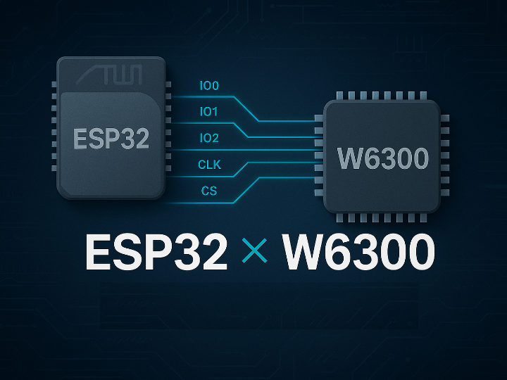
[ESP32-S3] Geekble Nano W6300 QSPI Porting
This content summarizes the process of configuring QSPI between the ESP32-S3 and W6300, analyzing waveforms, reading registers, and completing a loopback test.

Espressif - ESP32S
x 1
Overview
We aim to port the W6300 to the ESP32, provide a reference implementation for ESP32 users, and evaluate performance running on an RTOS.
Hardware Description
- Geekble nano

The Geekble Nano is a compact ESP32-S3 development board designed for easy prototyping.
It provides dual-core performance, built-in USB, plenty of GPIO pins, and support for Arduino, MicroPython, and ESP-IDF.
It’s small, powerful, and ideal for IoT projects.
- WIZ630io
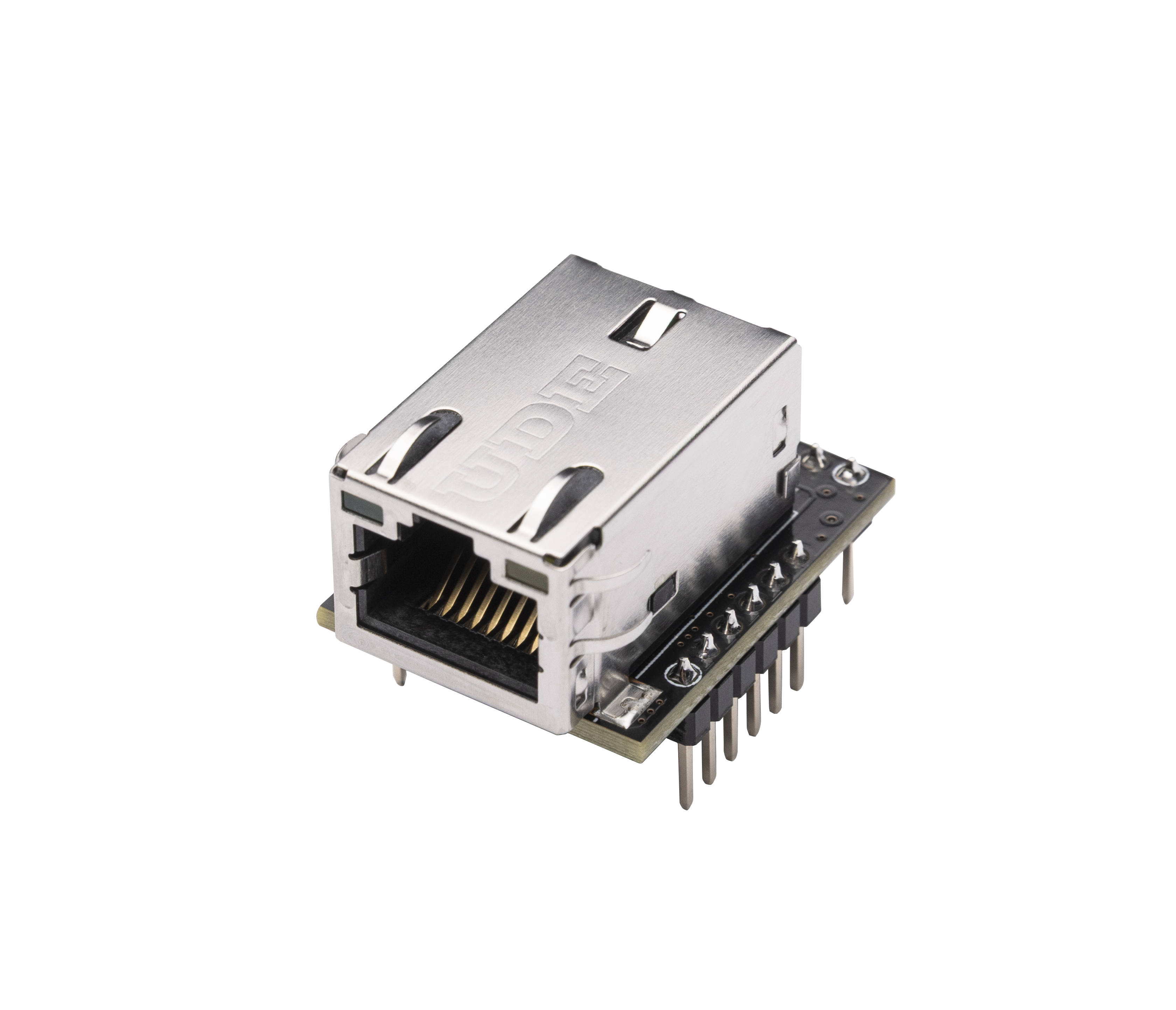
The WIZ630io is an Ethernet module based on the W6300 hardware TCP/IP chipset.
It offers stable 10/100Mbps Ethernet, built-in RJ45, and supports SPI/QSPI for fast communication with MCUs.
It makes adding wired networking simple and reliable.
PIN config
#define SPI_D0_PIN      47   // DATA0 (기존 MOSI)
#define SPI_D1_PIN      38   // DATA1 (기존 MISO)
#define SPI_D2_PIN      21   // DATA2 (WP) - 새로 추가
#define SPI_D3_PIN      18   // DATA3 (HD) - 새로 추가

#define SPI_CLK_PIN     17   // CLK
#define SPI_CS_PIN      10   // CS
QSPI config
 spi_device_handle_t spi_dev2;

    // SPI 버스 설정
    spi_bus_config_t buscfg = {
        .sclk_io_num = SPI_CLK_PIN,      // CLK

        .data0_io_num = SPI_D0_PIN,      // DATA0 (MOSI와 동일)
        .data1_io_num = SPI_D1_PIN,      // DATA1 (MISO와 동일)
        .data2_io_num = SPI_D2_PIN,      // DATA2 (WP)
        .data3_io_num = SPI_D3_PIN,      // DATA3 (HD)
        .data4_io_num = -1,              // OCTAL 모드용 (사용 안함)
        .data5_io_num = -1,              // OCTAL 모드용 (사용 안함)
        .data6_io_num = -1,              // OCTAL 모드용 (사용 안함)
        .data7_io_num = -1,              // OCTAL 모드용 (사용 안함)
        .max_transfer_sz = 4096,
        .flags = SPICOMMON_BUSFLAG_MASTER | SPICOMMON_BUSFLAG_QUAD,  // QUAD 모드 활성화

    };

    spi_device_interface_config_t devcfg = {
        .clock_speed_hz = 10000000,      // 10MHz (QSPI는 더 빠르게 가능)
        .mode = 0,                       // SPI mode 0
        .spics_io_num = SPI_CS_PIN,
        .queue_size = 1,
        .flags = SPI_DEVICE_HALFDUPLEX,  // QSPI는 일반적으로 half-duplex
    };

  // SPI 버스 초기화 (DMA 비활성화로 시작)
    ret = spi_bus_initialize(SPI2_HOST, &buscfg, SPI_DMA_DISABLED);
    if (ret != ESP_OK) {
        ESP_LOGE(TAG, "SPI bus init failed: %s", esp_err_to_name(ret));
        return;
    }

    ESP_LOGI(TAG, "QSPI bus initialized successfully");

    // SPI 디바이스 추가
    ret = spi_bus_add_device(SPI2_HOST, &devcfg, &spi_dev2);
    if (ret != ESP_OK) {
        ESP_LOGE(TAG, "SPI device add failed: %s", esp_err_to_name(ret));
        return;
    }
How to write data via SPI instance
 void qspi_write_data(uint8_t cmd , uint16_t addr, uint8_t *data, size_t len){
    esp_err_t ret;

    static uint8_t full_buffer[16];
    spi_transaction_t t;

    memset(&t, 0, sizeof(t));
    t.length =  len * 8 ;
    t.addr = addr;
    t.cmd = cmd | 0x20;
    t.tx_buffer = data ;
    t.rx_buffer = NULL;
    t.rxlength = 0;
    t.flags = SPI_TRANS_MODE_QIO  | SPI_TRANS_MULTILINE_ADDR    ;

     ret = spi_device_transmit(spi_dev, &t);
}

void qspi_read_data(uint8_t cmd , uint16_t addr, uint8_t *data, size_t len){
    esp_err_t ret;

    static uint8_t full_buffer[16];
    spi_transaction_t t;

    memset(&t, 0, sizeof(t));
    t.length = 0 ;
    t.addr = addr;
    t.cmd = cmd;
    t.tx_buffer = NULL ;
    t.rx_buffer = data ;
    t.rxlength = len * 8;
    t.flags = SPI_TRANS_MODE_QIO  | SPI_TRANS_MULTILINE_ADDR    ;
    ret = spi_device_transmit(spi_dev, &t);
}
The transaction is constructed by declaring a spi_transaction_t structure, setting the required cmd and address fields, and sending it using spi_device_transmit().
TEST signal

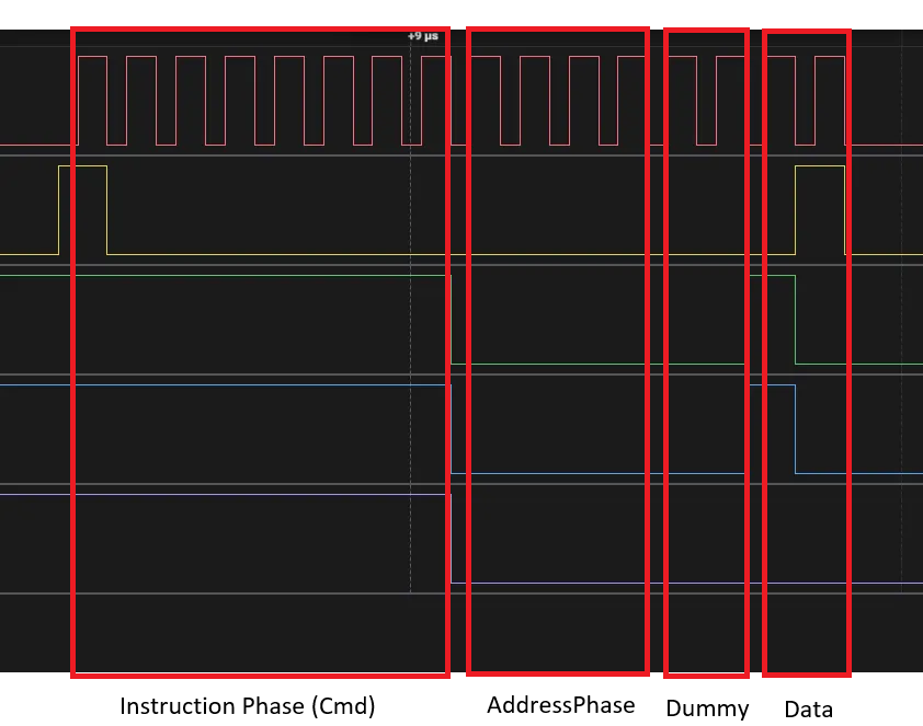
QSPI Read at Address 0x0000 – Waveform Analysis
This is the QSPI waveform for reading from address 0x0000.
The first section shows the CMD 0x80, which issues a Quad-Read command.
The next section is the address phase, where 0x0000 is sent.
After the address, dummy clocks follow, and in the final section, the actual data 0x61 is output.
In short: CMD (0x80) → ADDR (0x0000) → Dummy → DATA (0x61).
setup Network info


-
ESP32-W6300-Ethernet
