
Dual W6300 Ethernet Bypass with MACRAW
This project implements a transparent Ethernet bypass node using two W6300 chips in MACRAW mode, forwarding Ethernet frames between two ports via the RP2350.
W6300-Based MACRAW Ethernet Bypass Node
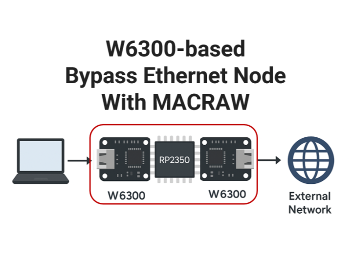
This project demonstrates how to build an Ethernet frame-level bypass node using two W6300 Ethernet controllers and an RP2350 microcontroller, operating in MACRAW mode.
While previous examples focused on loopback testing with a single W6300, this version extends the concept by relaying Ethernet frames between two W6300 chips. The RP2350 acts as a simple middle node that receives a frame from one W6300 and immediately forwards it to the other—without modifying the frame.
This architecture can be used as a transparent inline device between two network segments, suitable for packet filtering, monitoring, or traffic analysis.
HW Environment
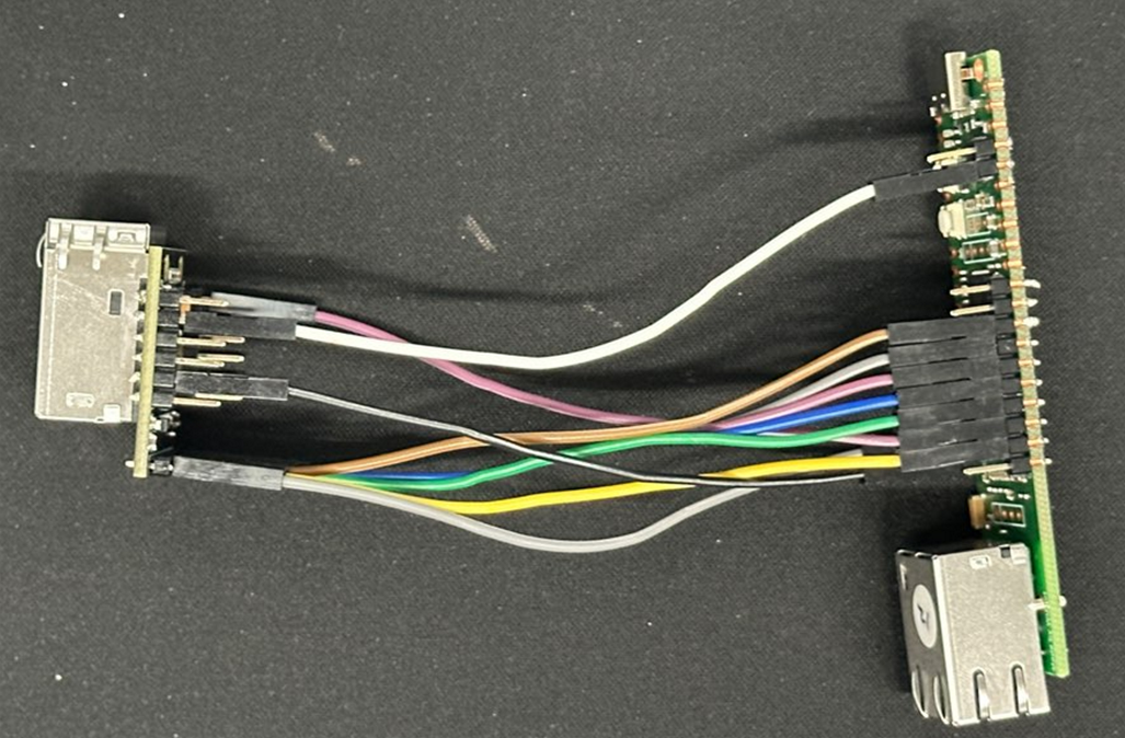
- WIZ630io modules
- W6300-EVB-PICO2
System Diagram
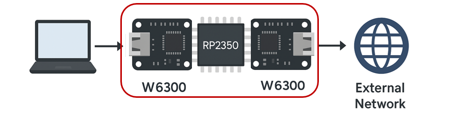
Laptop ⇄ W6300 ⇄ RP2350 ⇄ W6300 ⇄ External NetworkBoth W6300 chips are configured in MACRAW socket mode.
The RP2350 receives raw Ethernet frames from one chip and forwards them to the other.
- W6300 #0: receives Ethernet frames
- W6300 #1: transmits the frames
- No header modification or payload changes
What is MACRAW Mode?
MACRAW mode allows full control of raw Ethernet frames, including the header.
Unlike TCP or UDP sockets, which operate at Layer 4, MACRAW mode exposes the full Layer 2 packet directly to the application.
MACRAW vs. Standard Sockets
| Feature | Standard Sockets | MACRAW Sockets |
|---|---|---|
| Protocol Layer | TCP/UDP (L4) | Ethernet (L2) |
| Header Control | Not accessible | Fully accessible |
| Use Cases | Regular data communication | Frame filtering, analysis, bridging |
Why Use MACRAW?
Enables packet filtering, inspection, and modification
For example: MAC address-based filtering, ARP detection, broadcast suppression
Ideal for building intermediate nodes, firewall prototypes, or network analyzers
Implementation Overview
Initialize both W6300 chips in MACRAW mode
    /* chip init W6300_0*/
    set_cs_select(0);
    wizchip_initialize(); // spi initialization
    wizchip_check();
    network_initialize(g_net_info_0);
    print_network_information(g_net_info_0); // Read back the configuration information and print it
    /* chip init finish*/

    /* chip init W6300_1*/
    set_cs_select(1);
    wizchip_initialize(); // spi initialization
    wizchip_check();
    network_initialize(g_net_info_1);
    print_network_information(g_net_info_1); // Read back the configuration information and print it
    /* chip init finish*/


    int retval = socket(0, Sn_MR_MACRAW, 0, 0x20);
 // W6300_0
    int  retval2 = socket(8, Sn_MR_MACRAW, 0, 0x20 ); //W6300_1
On frame reception, copy the buffer and forward it to the other W6300
    while (true)
    {
        Ethernet_Frame_pass_through(0,8 ,recv_buf_0, sizeof(recv_buf_0));
        Ethernet_Frame_pass_through(8,0, recv_buf_1, sizeof(recv_buf_0));
    }
int32_t Ethernet_Frame_pass_through(uint8_t sn_source, uint8_t sn_dest, uint8_t *buf, uint32_t len)
{
volatile uint16_t recvsize = getSn_RX_RSR(sn_source); // Check the size of the received data available
while((recvsize) !=0 ){
if (recvsize == 0) return 0; // No data has been received yet
if (recvsize < len) len = recvsize; // Limit the requested data to avoid exceeding the buffer size
wiz_recv_data(sn_source, buf, len); // Store the received data in the buffer
// Wait until the command register is released
uint16_t freesize = getSn_TX_FSR(sn_dest);
// Check the Size of data
uint32_t len2 =((buf[0] << 8) | buf[1]) -2 ;
// Check if the data to be sent exceeds the maximum frame size
if (len2 > freesize) len2 = freesize;
// Send the data
wiz_send_data(sn_dest, buf+2, len2);
setSn_CR(sn_dest, Sn_CR_SEND); // Set the signal for completion of reception
setSn_CR(sn_source, Sn_CR_RECV);
while (getSn_CR(sn_source) & Sn_CR_RECV );
while (getSn_CR(sn_dest) & Sn_CR_SEND);
recvsize = getSn_RX_RSR(sn_source); // Check the size of the received data available
}
return (int32_t)len; // Return the actual size of the received data
}
Determine the target chip based on socket number
Dynamically select the correct CS pin before SPI transmission
Only minor adjustments were made to ioLibrary; the core structure is intact
Test Results
The bypass node—built with the dual W6300 setup—was placed between the PC and the router, creating a transparent inline path.
While we observed a slight performance drop due to frame relaying, all network functions worked as expected without any critical issues.
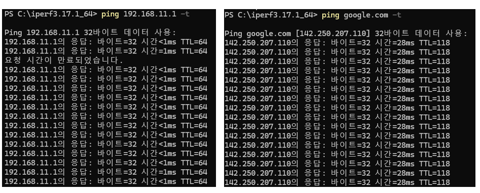
1. Ping Test
ICMP packets were successfully transmitted and received through the bypass node, confirming proper frame forwarding and MAC address resolution.
2. YouTube Streaming Test
The PC was connected to the network exclusively through the W6300-based bypass node, with all other network interfaces (Wi-Fi, secondary LAN, etc.) disabled during the test.
In this setup, we streamed HD videos on YouTube without any interruptions, confirming that the bypass node can reliably handle real-world streaming traffic.
This project shows how to build a lightweight Ethernet bridge at the frame level using minimal hardware.
It can serve as a foundation for future use cases such as:
MAC-based filtering
Packet logging or monitoring
Simple Layer 2 firewalls
Feel free to build upon this concept to suit your own networking experiments!