
dblocker_control_imip
Drone Blocker Control Center
DBlocker Control — A Field-Hardened Counter-Drone Controller, Networked Over W5500
#CounterDrone #IndustrialIoT #W5500 #TOE #UDP #MQTT #STM32 #OTA #EdgeAI #YOLOv8
📚 Context: Industrial deployment — a counter-drone (drone-defense) control and monitoring system, by the look of it fielded at a large industrial site (the repo and docs reference IMIP / a drone-blocker deployment). Implementation status: Full production stack — STM32 master/slave firmware with WIZnet W5500 networking, OTA update, a Go + MQTT backend, a YOLOv8 vision detector, and a Svelte web dashboard. Live static-IP addressing, watchdogs, and field-recovery logic indicate a real deployment, not a bench demo.
01 — What is this project?
A modern industrial site has to assume the sky is hostile. Unauthorized drones over a refinery, a smelter, or a logistics yard are a safety and security problem, and the response has to be reliable around the clock with nobody standing next to the hardware. The hard part isn't a single gadget — it's making detection, control, telemetry, and remote maintenance all keep working unattended, on an industrial LAN, for months.
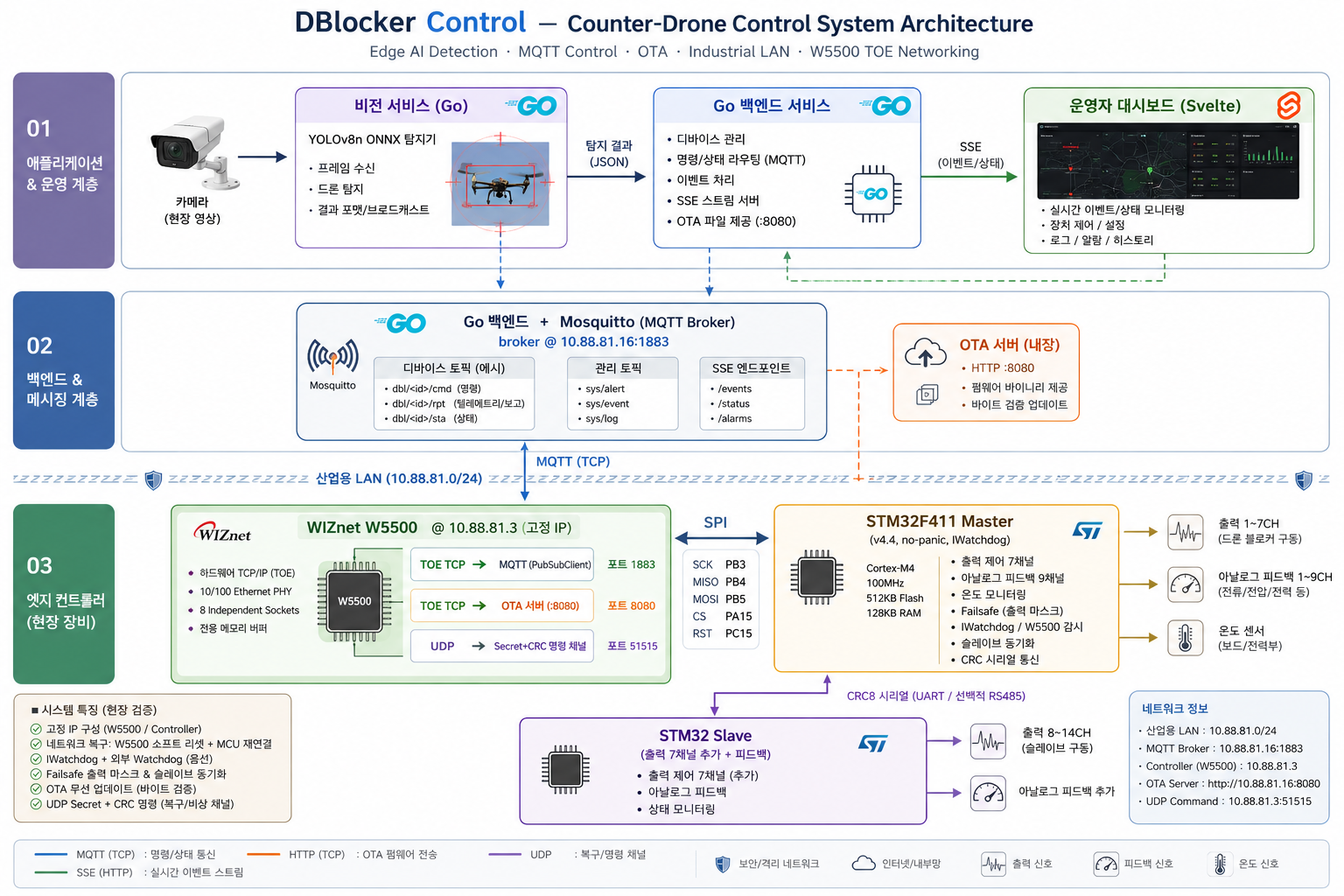
DBlocker Control is the full control plane for exactly that kind of counter-drone deployment. It ties together four layers into one operable system:
- Edge AI detection — a Go vision service runs a YOLOv8 ONNX model against camera streams to spot drones and broadcast detections.
- Field controller — an STM32F411 "master" microcontroller drives the blocker hardware (seven master output channels plus seven more on a serial-linked slave STM32), reads analog feedback and temperature, and reports state.
- Messaging + backend — a Go backend speaks MQTT (Mosquitto) to the controllers and fans events out to operators over Server-Sent Events.
- Operator dashboard — a Svelte web frontend for live monitoring and command.
The whole thing is containerized with Docker Compose for production deployment. And the single component that keeps the field controller reachable — for control, for telemetry, and for over-the-air firmware updates — is the WIZnet W5500. This curation focuses on that controller's networking, because it is a textbook case of squeezing professional-grade, self-healing connectivity out of a small microcontroller.
02 — Why a hardware network stack on the controller?
🔷 The controller must never silently fall off the network
This is safety equipment. If the link dies, the firmware runs a deliberate safety shutdown (apply a failsafe pin mask, sync the slave) and then works hard to recover. For that logic to be trustworthy, the network layer itself has to be rock-solid and, crucially, resettable on demand — which is exactly what a dedicated hardware Ethernet controller offers over a soft stack tangled into the application.
🔷 The STM32F411 has no Ethernet — and shouldn't carry a TCP/IP stack
The STM32F411CEU6 is a Cortex-M4 with no Ethernet MAC. Bolting a software TCP/IP stack onto a controller whose real job is real-time I/O, CRC-checked serial to a slave, watchdog servicing, and OTA would bloat the firmware and steal cycles from the control loop. Offloading TCP/IP to a hardware chip keeps the firmware lean and the timing predictable.
🔷 MQTT-native industrial messaging
The controller publishes telemetry and subscribes to commands over MQTT — the de-facto industrial IoT messaging pattern. Running a standard PubSubClient on top of a hardware TCP socket is the simplest, most reliable way to get there from an MCU.
🔷 Where WIZnet fits
Among SPI-attached networking parts, the W5500 is the one that brings a complete hardwired TCP/UDP/IP stack with eight independent sockets and a 10/100 PHY in a single chip. For a controller that needs MQTT, an OTA TCP server, and a UDP command channel all at once, those parallel hardware sockets are the decisive feature.
03 — System architecture
04 — Why WIZnet W5500? ⭐
🔷 The technical core: one SPI chip, a full hardware TCP/IP stack
The W5500 hangs off the STM32's SPI bus (SCK=PB3, MISO=PB4, MOSI=PB5, CS=PA15) with a dedicated reset line (PC15), and presents a complete hardwired TCP/UDP/IP stack plus a 10/100 PHY. The STM32 talks to it through the standard Arduino Ethernet library — no software TCP/IP on the MCU at all.
🔷 Modes in use: TOE TCP and UDP, simultaneously
This project is a clean illustration of the W5500's multi-socket hardware offload, using several of its eight hardware sockets at the same time:
- TOE TCP — MQTT.
EthernetClientcarries aPubSubClientMQTT session to the broker. The controller publishes 18 channels of analog feedback + temperature + slave-link status ondbl/<id>/rpt, subscribes todbl/<id>/cmd, and uses an MQTT Last-Will (sta=OFF) so the backend learns instantly if the controller drops. TCP socket, hardware-offloaded. - TOE TCP — OTA server.
EthernetServer otaServer(8080)is a listening TCP socket that accepts a new firmware image, streams it into internal flash, and applies it only after a strict byte-for-byte size verification — otherwise it discards and reboots. Remote firmware update over a hardware TCP socket. - UDP — secure out-of-band command channel.
EthernetUDPon port 51515 receives short commands (SLEEP,WAKE,WAKE_RST, and an OTA trigger), each guarded by a shared secret + CRC, and replies with ACK/ERR datagrams. This is the lifeline that can wake the controller or push it into OTA mode even when MQTT is down. UDP socket.
Running MQTT, an OTA TCP server, and a UDP listener concurrently is precisely what the W5500's independent hardware sockets are built for — and it would be painful to juggle on a single software socket.
🔷 Field-hardening: the W5500 as a recoverable subsystem
What makes this a professional use of the chip is how aggressively the firmware treats the W5500 as something it can monitor and recover:
- A
resetW5500()routine toggles the hardware RST line and fully re-initializes SPI, the Ethernet stack, the UDP listener, and MQTT. - At boot the firmware tries W5500 init up to 3 times, hard-resetting between attempts, and checks
Ethernet.hardwareStatus(). - It watches
Ethernet.linkStatus(); a sustained link-down triggers the safety shutdown. - A W5500 health timeout detects the nasty "connected but publishes silently failing" lockup — if no successful publish happens for 60 s while ostensibly connected, it resets the chip.
- MQTT reconnect failures escalate to a W5500 reset after a threshold; a longer outage escalates to a full reboot. An
IWatchdogbackstops everything.
That escalation ladder — retry → reset the W5500 → reboot — is only clean to write because the W5500 is a discrete, resettable network engine with a hardware reset pin. A soft stack fused into the MCU couldn't be power-cycled like that.
🔷 Advantages over the alternatives
A software stack (e.g. lwIP/smoltcp on an Ethernet-capable MCU) would consume flash and CPU the control loop needs, and couldn't be hard-reset independently. An ENC28J60 would force the MCU to run TCP/IP in software anyway (it's MAC-only). The W5500 gives this small STM32 a full TCP/IP offload, multiple concurrent sockets, and a hardware reset line — the trifecta this always-on safety controller actually depends on.
🔷 Verified evidence ✅
- Live, fixed addressing of a real deployment: controller at
10.88.81.3, broker at10.88.81.16, controller ID250002. - Complete W5500 bring-up and recovery code in firmware (
mcu_master_4.x.ino): SPI pins, reset sequence, init retries, link monitoring. - Concurrent socket use proven in code: MQTT TCP + OTA
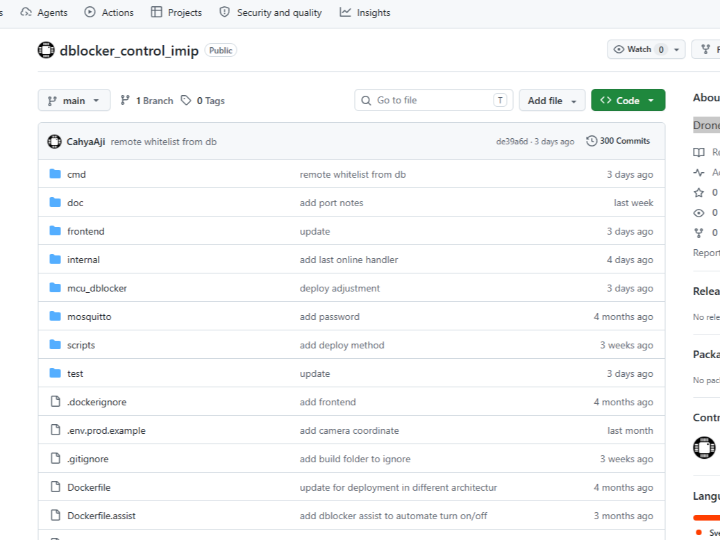
EthernetServer(8080)+EthernetUDP(51515). - Production tooling around it: Docker Compose deploy files, deployment/auth/port docs, OTA with byte verification, and a vision pipeline shipping a real
yolov8n.onnxmodel.
05 — Key components
🌐 WIZnet W5500 — TOE TCP + UDP, SPI-attached full stack
The controller's sole network link. Provides hardware TCP/IP across multiple sockets (MQTT, OTA server, UDP) and a 10/100 PHY, with a hardware reset line the firmware uses for recovery. SPI: SCK=PB3, MISO=PB4, MOSI=PB5, CS=PA15, RST=PC15.
🎛️ STM32F411 master + STM32 slave
The master drives 7 output channels, reads 9 analog feedback inputs and temperature, and commands a slave (7 more channels) over CRC8-framed serial (UART, optional RS485). Failsafe pin mask + safety shutdown on link loss.
📡 MQTT (Mosquitto) + Go backend
Topic scheme dbl/<id>/{cmd,rpt,sta} with Last-Will. The Go backend bridges MQTT to a database and to operators via SSE.
👁️ YOLOv8 vision detector (Go)
A yolov8n.onnx model runs against camera streams to detect drones and broadcast detections — the "eyes" feeding the control plane.
🖥️ Svelte dashboard
Live operator UI for monitoring feedback/telemetry and issuing commands.
06 — Application scenarios
01. Unattended perimeter drone defense
A controller at a fixed industrial-LAN address runs around the clock, executing a safe-state shutdown on network loss and self-recovering its W5500 link — no on-site intervention needed.
02. Remote firmware maintenance at scale
Field units get new firmware over the W5500's TCP OTA server with byte-for-byte verification, so a fleet across a large site can be updated from the control room without physical access.
03. Out-of-band recovery when MQTT is down
The CRC-and-secret UDP channel on 51515 can wake a sleeping controller or push it into OTA mode even if the broker connection has failed — a true backdoor lifeline over a separate hardware socket.
04. AI-detection-driven response
YOLOv8 drone detections flow through MQTT to the controllers, closing the loop from "camera sees a drone" to "controller acts," all over the same W5500-backed network.
Conclusion
DBlocker Control shows what a single WIZnet W5500 buys a small STM32: MQTT control, OTA updates, and an out-of-band UDP lifeline running concurrently on hardware sockets — with a hardware reset pin that turns the network link into something the firmware can monitor and heal on its own.
- ✅ Full counter-drone control stack: edge AI, firmware, MQTT backend, web dashboard
- ✅ W5500 used in TOE TCP and UDP simultaneously across multiple hardware sockets
- ✅ MQTT control/telemetry with Last-Will over a hardware TCP socket
- ✅ OTA firmware update via a TCP
EthernetServer, with strict byte verification - ✅ Secret-+-CRC UDP command channel as an out-of-band recovery path
- ✅ Aggressive W5500 field-hardening: init retries, health timeout, reset/reboot escalation, watchdog
- ✅ Real deployment markers: static industrial IPs, Docker Compose, deployment docs, shipped YOLOv8 model
- ✅ Master/slave STM32 architecture with CRC-framed serial and failsafe safe-state
Q&A
Q. Which W5500 mode does the controller use? Both TOE TCP and UDP, at the same time. Via the Arduino Ethernet library the W5500 runs its hardwired TCP/IP: a TCP socket for MQTT (PubSubClient), a second TCP socket as an OTA server on :8080, and a UDP socket on :51515 for secret-protected out-of-band commands. The W5500's eight independent hardware sockets are what make running all three concurrently straightforward.
Q. Why hardware TCP/IP (TOE) instead of a software stack? The STM32F411 has no Ethernet MAC and its firmware is busy with real-time I/O, CRC serial, OTA, and watchdog duties. Offloading TCP/IP to the W5500 keeps the firmware lean and timing predictable — and, vitally, the W5500's hardware reset line lets the firmware power-cycle the whole network engine as a recovery step, which a fused-in soft stack can't do.
Q. What happens when the network drops? The firmware escalates: reconnect attempts → reset the W5500 → full reboot, with an IWatchdog backstop, and a deliberate safety shutdown (failsafe pin mask) if the link stays down. A W5500 "health timeout" also catches the connected-but-silently-failing lockup and resets the chip.
Q. Is the deployment real? The static industrial addressing, controller ID, Docker Compose production files, deployment/port/auth docs, OTA-with-verification, and a shipped YOLOv8 model all point to a fielded system rather than a bench demo. (Anyone reproducing it should still validate on their own hardware and network.)
DBlocker Control — W5500로 네트워크를 잇는, 현장 검증형 카운터드론 컨트롤러
#CounterDrone #IndustrialIoT #W5500 #TOE #UDP #MQTT #STM32 #OTA #EdgeAI #YOLOv8
📚 컨텍스트: 산업 현장 배치 — 카운터드론(드론 방어) 제어·모니터링 시스템. 레포와 문서 정황상 대형 산업단지(IMIP / drone-blocker 배치)에 투입된 것으로 보임. 구현 상태: 완전한 production 스택 — WIZnet W5500 네트워킹을 쓰는 STM32 마스터/슬레이브 펌웨어, OTA 업데이트, Go + MQTT 백엔드, YOLOv8 비전 탐지기, Svelte 웹 대시보드. 고정 IP, 워치독, 현장 복구 로직이 실제 배치임을 시사.
01 — 이 프로젝트는 무엇인가?
현대 산업 현장은 하늘이 적대적일 수 있다고 가정해야 한다. 정유소·제련소·물류 야적장 위로 날아드는 허가받지 않은 드론은 안전·보안 문제이며, 그 대응은 곁에 사람이 없어도 24시간 신뢰성 있게 동작해야 한다. 어려운 부분은 단일 장치가 아니다 — 탐지, 제어, 텔레메트리, 원격 유지보수 가 산업용 LAN 위에서 무인으로 수개월간 전부 동작하게 만드는 것이다.
DBlocker Control은 바로 그런 카운터드론 배치를 위한 완전한 컨트롤 플레인이다. 네 개의 계층을 하나의 운용 가능한 시스템으로 묶는다.
- 엣지 AI 탐지 — Go 비전 서비스가 카메라 스트림에 YOLOv8 ONNX 모델을 돌려 드론을 탐지하고 결과를 브로드캐스트한다.
- 현장 컨트롤러 — STM32F411 "마스터" 마이크로컨트롤러가 blocker 하드웨어(마스터 출력 7채널 + 시리얼로 연결된 슬레이브 STM32의 7채널)를 구동하고, 아날로그 피드백과 온도를 읽고, 상태를 보고한다.
- 메시징 + 백엔드 — Go 백엔드가 MQTT(Mosquitto)로 컨트롤러와 통신하고, 이벤트를 SSE로 운영자에게 팬아웃한다.
- 운영자 대시보드 — 실시간 모니터링·명령용 Svelte 웹 프론트엔드.
전체는 production 배포를 위해 Docker Compose로 컨테이너화돼 있다. 그리고 현장 컨트롤러를 — 제어용으로도, 텔레메트리용으로도, 무선 펌웨어 업데이트용으로도 — 도달 가능하게 유지하는 단 하나의 부품이 WIZnet W5500이다. 이번 큐레이션은 그 컨트롤러의 네트워킹에 초점을 맞춘다. 작은 마이크로컨트롤러에서 전문가급의 자가 치유 연결성을 짜내는 교과서적 사례이기 때문이다.
02 — 왜 컨트롤러에 하드웨어 네트워크 스택인가?
🔷 컨트롤러는 절대 조용히 네트워크에서 떨어져선 안 된다
이건 안전 장비다. 링크가 죽으면 펌웨어는 의도된 세이프티 셧다운(failsafe 핀 마스크 적용, 슬레이브 동기화)을 실행하고 복구에 총력을 기울인다. 그 로직이 신뢰받으려면 네트워크 계층 자체가 견고해야 하고, 결정적으로 필요할 때 리셋 가능 해야 한다 — 애플리케이션에 얽혀 들어간 소프트 스택보다 전용 하드웨어 이더넷 컨트롤러가 정확히 그것을 제공한다.
🔷 STM32F411은 이더넷이 없고 — TCP/IP 스택을 짊어져선 안 된다
STM32F411CEU6는 이더넷 MAC이 없는 Cortex-M4다. 실시간 I/O, 슬레이브로의 CRC 시리얼, 워치독 서비스, OTA가 본업인 컨트롤러에 소프트웨어 TCP/IP 스택까지 얹으면 펌웨어가 비대해지고 제어 루프의 사이클을 빼앗긴다. TCP/IP를 하드웨어 칩에 오프로드하면 펌웨어는 가볍고 타이밍은 예측 가능해진다.
🔷 MQTT 네이티브 산업 메시징
컨트롤러는 MQTT로 텔레메트리를 publish 하고 명령을 subscribe 한다 — 사실상 산업 IoT 메시징의 표준이다. 하드웨어 TCP 소켓 위에서 표준 PubSubClient를 돌리는 것이 MCU에서 거기 도달하는 가장 단순하고 신뢰성 있는 방법이다.
🔷 WIZnet의 위치
SPI 부착 네트워킹 부품 중에서, 완전한 하드와이어드 TCP/UDP/IP 스택과 8개 독립 소켓, 10/100 PHY를 단일 칩으로 가져오는 것이 W5500이다. MQTT, OTA TCP 서버, UDP 명령 채널이 동시에 필요한 컨트롤러에게 이 병렬 하드웨어 소켓이 결정적 기능이다.
03 — 시스템 아키텍처

04 — 왜 WIZnet W5500인가? ⭐
🔷 기술적 핵심: SPI 칩 하나에 완전한 하드웨어 TCP/IP 스택
W5500은 STM32의 SPI 버스(SCK=PB3, MISO=PB4, MOSI=PB5, CS=PA15)에 전용 reset 라인(PC15)과 함께 매달려, 완전한 하드와이어드 TCP/UDP/IP 스택과 10/100 PHY를 제공한다. STM32는 표준 Arduino Ethernet 라이브러리로 칩과 통신한다 — MCU에는 소프트웨어 TCP/IP가 전혀 없다.
🔷 사용 모드: TOE TCP 와 UDP 를 동시에
이 프로젝트는 W5500의 멀티소켓 하드웨어 오프로드를 깔끔하게 보여준다. 8개 하드웨어 소켓 중 여럿을 동시에 쓴다.
- TOE TCP — MQTT.
EthernetClient가PubSubClientMQTT 세션을 브로커로 실어 나른다. 컨트롤러는 18채널 아날로그 피드백 + 온도 + 슬레이브 링크 상태를dbl/<id>/rpt로 publish 하고,dbl/<id>/cmd를 subscribe 하며, MQTT Last-Will(sta=OFF)을 써서 컨트롤러가 떨어지면 백엔드가 즉시 알게 한다. 하드웨어 오프로드된 TCP 소켓. - TOE TCP — OTA 서버.
EthernetServer otaServer(8080)은 새 펌웨어 이미지를 받아 내부 플래시로 스트리밍하고, 엄격한 바이트 단위 크기 검증 후에만 적용하는(아니면 폐기·재부팅) 리스닝 TCP 소켓이다. 하드웨어 TCP 소켓 위 원격 펌웨어 업데이트. - UDP — 보안 대역외 명령 채널. 포트 51515의
EthernetUDP가 짧은 명령(SLEEP,WAKE,WAKE_RST, OTA 트리거)을 받는데, 각각 공유 비밀키 + CRC로 보호되고 ACK/ERR 데이터그램으로 응답한다. MQTT가 죽었을 때조차 컨트롤러를 깨우거나 OTA 모드로 밀어넣을 수 있는 생명줄. UDP 소켓.
MQTT, OTA TCP 서버, UDP 리스너를 동시에 돌리는 것 — 이것이 바로 W5500의 독립 하드웨어 소켓이 존재하는 이유다. 단일 소프트웨어 소켓으로는 곡예가 됐을 일이다.
🔷 현장 하드닝: 복구 가능한 서브시스템으로서의 W5500
이 칩을 전문가답게 쓴다는 증거는, 펌웨어가 W5500을 감시·복구 가능한 대상으로 얼마나 적극적으로 다루는지에 있다.
resetW5500()루틴이 하드웨어 RST 라인을 토글하고 SPI·이더넷 스택·UDP 리스너·MQTT를 전부 재초기화한다.- 부팅 시 펌웨어는 W5500 init을 최대 3회 시도하며, 시도 사이에 하드 리셋하고
Ethernet.hardwareStatus()를 확인한다. Ethernet.linkStatus()를 감시하고, 지속적인 링크 다운은 세이프티 셧다운을 트리거한다.- W5500 헬스 타임아웃이 "연결돼 있는데 publish가 조용히 실패하는" 고약한 락업을 잡아낸다 — 연결된 듯한데 60초간 성공적 publish가 없으면 칩을 리셋한다.
- MQTT 재연결 실패가 임계치를 넘으면 W5500 리셋으로, 더 긴 장애는 전체 재부팅으로 에스컬레이션.
IWatchdog이 모든 것을 받쳐준다.
retry → W5500 리셋 → 재부팅이라는 그 에스컬레이션 사다리는, W5500이 하드웨어 reset 핀을 가진 분리된, 리셋 가능한 네트워크 엔진이기에 깔끔하게 짜인다. MCU에 융합된 소프트 스택은 그렇게 전원을 껐다 켤 수 없다.
🔷 대체 솔루션 대비 우위
소프트웨어 스택(예: 이더넷 가능 MCU 위의 lwIP/smoltcp)은 제어 루프가 필요로 하는 플래시·CPU를 잡아먹고, 독립적으로 하드 리셋할 수도 없다. ENC28J60은 MAC 전용이라 MCU가 결국 TCP/IP를 소프트웨어로 돌려야 한다. W5500은 이 작은 STM32에 완전한 TCP/IP 오프로드, 다중 동시 소켓, 그리고 하드웨어 reset 라인을 준다 — 이 상시 가동 안전 컨트롤러가 실제로 의지하는 3박자다.
🔷 검증된 증거 ✅
- 실제 배치의 고정 주소: 컨트롤러
10.88.81.3, 브로커10.88.81.16, 컨트롤러 ID250002. - 펌웨어 내 완전한 W5500 초기화·복구 코드(
mcu_master_4.x.ino): SPI 핀, 리셋 시퀀스, init 재시도, 링크 감시. - 코드에서 입증된 동시 소켓 사용: MQTT TCP + OTA
EthernetServer(8080)+EthernetUDP(51515). - 주변 production 도구: Docker Compose 배포 파일, 배포/인증/포트 문서, 바이트 검증 OTA, 실제
yolov8n.onnx모델을 싣는 비전 파이프라인.
05 — 핵심 컴포넌트
🌐 WIZnet W5500 — TOE TCP + UDP, SPI 부착 풀 스택
컨트롤러의 유일한 네트워크 링크. 다중 소켓(MQTT, OTA 서버, UDP)에 걸친 하드웨어 TCP/IP와 10/100 PHY를 제공하고, 펌웨어가 복구에 쓰는 하드웨어 reset 라인을 갖는다. SPI: SCK=PB3, MISO=PB4, MOSI=PB5, CS=PA15, RST=PC15.
🎛️ STM32F411 마스터 + STM32 슬레이브
마스터는 출력 7채널을 구동하고, 아날로그 피드백 9개와 온도를 읽으며, CRC8 프레이밍 시리얼(UART, 선택적 RS485)로 슬레이브(7채널 추가)에 명령한다. 링크 상실 시 failsafe 핀 마스크 + 세이프티 셧다운.
📡 MQTT (Mosquitto) + Go 백엔드
Last-Will을 갖춘 dbl/<id>/{cmd,rpt,sta} 토픽 체계. Go 백엔드가 MQTT를 DB로, 그리고 SSE로 운영자에게 브리지한다.
👁️ YOLOv8 비전 탐지기 (Go)
yolov8n.onnx 모델이 카메라 스트림에 돌아 드론을 탐지하고 결과를 브로드캐스트 — 컨트롤 플레인을 먹이는 "눈".
🖥️ Svelte 대시보드
피드백/텔레메트리 모니터링과 명령 발행을 위한 실시간 운영자 UI.
06 — 활용 시나리오
01. 무인 경계 드론 방어
고정 산업 LAN 주소의 컨트롤러가 24시간 가동되며, 네트워크 상실 시 안전 상태 셧다운을 실행하고 W5500 링크를 자가 복구한다 — 현장 개입 불필요.
02. 대규모 원격 펌웨어 유지보수
현장 유닛이 W5500의 TCP OTA 서버를 통해, 바이트 단위 검증과 함께 새 펌웨어를 받는다. 대형 사이트 전체 함대를 물리적 접근 없이 관제실에서 업데이트.
03. MQTT 다운 시 대역외 복구
51515의 CRC·비밀키 UDP 채널이 브로커 연결이 실패해도 잠든 컨트롤러를 깨우거나 OTA 모드로 밀어넣을 수 있다 — 별도 하드웨어 소켓 위의 진짜 백도어 생명줄.
04. AI 탐지 기반 대응
YOLOv8 드론 탐지가 MQTT로 컨트롤러에 흘러, "카메라가 드론을 본다"에서 "컨트롤러가 동작한다"까지의 루프를 닫는다 — 전부 같은 W5500 기반 네트워크 위에서.
결론
DBlocker Control은 작은 STM32 하나에 WIZnet W5500이 무엇을 사주는지 보여준다: MQTT 제어, OTA 업데이트, 대역외 UDP 생명줄이 하드웨어 소켓 위에서 동시에 돌고 — 펌웨어가 스스로 감시·치유할 수 있는 네트워크 링크로 만드는 하드웨어 reset 핀까지.
- ✅ 완전한 카운터드론 제어 스택: 엣지 AI, 펌웨어, MQTT 백엔드, 웹 대시보드
- ✅ 여러 하드웨어 소켓에 걸쳐 W5500을 TOE TCP 와 UDP 동시 사용
- ✅ 하드웨어 TCP 소켓 위 Last-Will 포함 MQTT 제어/텔레메트리
- ✅ TCP
EthernetServer를 통한 OTA 펌웨어 업데이트, 엄격한 바이트 검증 - ✅ 대역외 복구 경로로서의 비밀키+CRC UDP 명령 채널
- ✅ 공격적 W5500 현장 하드닝: init 재시도, 헬스 타임아웃, 리셋/재부팅 에스컬레이션, 워치독
- ✅ 실제 배치 흔적: 고정 산업 IP, Docker Compose, 배포 문서, 동봉된 YOLOv8 모델
- ✅ CRC 프레이밍 시리얼과 failsafe 안전 상태를 갖춘 마스터/슬레이브 STM32 구조
Q&A
Q. 컨트롤러는 W5500의 어떤 모드를 쓰나요? TOE TCP 와 UDP 를 동시에 씁니다. Arduino Ethernet 라이브러리를 통해 W5500이 하드와이어드 TCP/IP를 돌립니다: MQTT용 TCP 소켓(PubSubClient), :8080의 OTA 서버용 두 번째 TCP 소켓, 그리고 비밀키로 보호되는 대역외 명령용 :51515 UDP 소켓. W5500의 8개 독립 하드웨어 소켓 덕에 셋을 동시에 돌리는 게 수월합니다.
Q. 왜 소프트웨어 스택이 아니라 하드웨어 TCP/IP(TOE)인가요? STM32F411은 이더넷 MAC이 없고 펌웨어는 실시간 I/O, CRC 시리얼, OTA, 워치독으로 바쁩니다. TCP/IP를 W5500에 오프로드하면 펌웨어가 가볍고 타이밍이 예측 가능해지며 — 무엇보다 W5500의 하드웨어 reset 라인 덕에 펌웨어가 네트워크 엔진 전체를 복구 단계로 전원 재투입할 수 있습니다. 융합된 소프트 스택은 못 하는 일입니다.
Q. 네트워크가 끊기면 어떻게 되나요? 펌웨어가 에스컬레이션합니다: 재연결 시도 → W5500 리셋 → 전체 재부팅, IWatchdog이 받쳐주고, 링크가 계속 끊겨 있으면 의도된 세이프티 셧다운(failsafe 핀 마스크). W5500 "헬스 타임아웃"이 연결된-듯-조용히-실패하는 락업도 잡아 칩을 리셋합니다.
Q. 실제 배치된 시스템인가요? 고정 산업 주소, 컨트롤러 ID, Docker Compose production 파일, 배포/포트/인증 문서, 검증 포함 OTA, 동봉된 YOLOv8 모델이 모두 벤치 데모가 아닌 현장 시스템을 가리킵니다. (재현하는 쪽은 그래도 자체 하드웨어·네트워크에서 검증하는 게 좋습니다.)