
Arduino Ethernet/USB Interface for Yaesu Rotators
Arduino-based interface to control Yaesu antenna rotators from a PC using USB or Ethernet. Emulates the standard GS-232 protocol for wide software compatibility
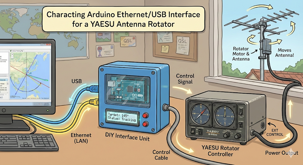
Arduino Ethernet/USB Interface for YAESU Antenna Rotator
1. Project Background & Concept


YAESU is a well-known Japanese manufacturer specializing in radio communication equipment.
They are primarily known for producing high-performance transceivers, receivers, and various accessories for the amateur radio (Ham Radio) market. YAESU is considered one of the top three most trusted and prominent brands in the global amateur radio community, alongside Icom and Kenwood.
The "antenna rotator" featured in the project you inquired about earlier is a typical accessory manufactured by YAESU, designed to remotely rotate heavy directional antennas to adjust the signal direction.
Limitations and Problems of Existing Solutions
Generally, in Amateur Radio (Ham Radio), there were only two options to control an antenna rotator via PC.
High Cost: You must purchase a new, latest commercial controller (with built-in PC interface) that costs hundreds of dollars.
High Complexity: You must completely remove the existing controller and build a complex DIY controller (e.g., 'K3NG rotator') from scratch. This has the disadvantage of high difficulty in fabrication and having to discard existing equipment.
Core Idea: "Stock-Keeping Add-on"
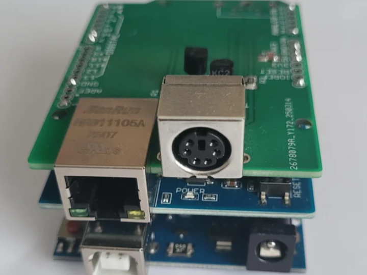
The core of this project is "not discarding the reliability of the existing YAESU stock controller." The YAESU controller is mechanically very sturdy and highly reliable. Therefore, this project is designed in a way that the Arduino 'parasites' on the stock equipment by utilizing the EXT CONTROL port (DIN connector) on the back of the controller. Through this, users can maintain the physical button operation functions of the controller as is, while adding PC remote control functionality at a low cost.
2. Technical Deep Dive
This system is largely divided into three modules: Control, Sensing, and Connectivity.
A. Motor Rotation Control (Output Logic)
The Arduino does not supply power directly to the motor but uses a method similar to "Open Collector" that triggers the circuit of the stock controller.
Operating Mechanism: The YAESU controller is designed so that the motor rotates when the rear control pin (Right or Left) is connected (Short) to Ground (GND).
Role of Arduino: The digital pins (D6, D7) of the Arduino are connected to the Base of an NPN Transistor (BC238 or BC546).
According to PC commands, the Arduino sends a HIGH signal to the pin.
The transistor turns on (Switch ON).
Consequently, the control pin of the rotator controller drops to GND via the transistor.
As a result, the motor rotates.
Hardware Safety: The transistor switching circuit is very simple, so failures rarely occur. Also, a lock is applied via software so that CW (Clockwise) and CCW (Counter-Clockwise) signals do not go out simultaneously.
B. Antenna Direction (Azimuth) Detection (Input Logic)
Voltage Division Principle: Inside the rotator, a precision potentiometer (variable resistor) is built-in, whose resistance value changes as the antenna rotates.
Voltage Reading: This variable resistor outputs an analog voltage between approximately 0V (0 degrees) and 4V (max angle) in proportion to the current antenna position.
ADC Processing: The Arduino's analog input pin (A0) reads this voltage. The firmware reads the digital value between 0~1023, converts it into the actual angle (e.g., 0~360 degrees or 450 degrees) through mathematical calculation, and transmits it to the PC.
3. Communication Interface: The Role and Necessity of Ethernet (Ethernet Connectivity)
In this project, the application of the Ethernet Shield is not just a simple option, but a key factor determining the completeness of the system.
① Technical Role of Ethernet
Network Communication Gateway: The Ethernet shield makes the Arduino an independent device on the local network.
TCP Server (Port 2823): The Arduino operates as a TCP server, receiving command packets such as "Rotate to 180 degrees" sent by PC control programs (PstRotatorAZ, etc.) and transmitting current angle data.
USB Replacement: It replaces the existing 1:1 serial connection (USB) method with a network connection capable of Many-to-One communication.
② Why Must It Be Ethernet? (Why Ethernet?)
Although control is possible with USB connection alone, Ethernet is essential in actual operating environments due to the following fatal reasons.
Complete Resolution of Physical Distance Constraints:
Limit of USB: USB cables usually cannot exceed 5 meters in length to guarantee data transmission stability. That is, the PC must be right next to the controller.
Advantage of Ethernet: LAN cables can theoretically connect up to 100 meters, and if passing through a router, distance limits virtually disappear. You can place antenna equipment in a roof warehouse or balcony and place the control PC in a living room or study far away.
Implementation of True Remote Control (Remote Shack):
If you connect to the internet network via Ethernet and set up port forwarding, you can control the antenna at home via smartphone or laptop even from outside the house. This is essential for building a 'Remote Shack' where you operate a radio station from work or a travel destination.
RF Noise Interference Prevention (Noise Immunity):
RFI Problem: In a Ham Radio (radio station) environment, strong radio frequency (RF) waves are generated during transmission. A long USB cable itself acts as an antenna, receiving Radio Frequency Interference (RFI) or introducing noise to the PC, causing malfunctions.
Electrical Isolation: Ethernet (LAN cable) is well shielded, making it much more resistant to noise during long-distance transmission, and has an electrical isolation effect through a transformer, which is advantageous for electrically separating the PC and radio equipment.
4. Importance of Power Supply and Precautions (Critical Power Issues)
This part is the 'point prone to failure' that the creator emphasizes the most.
Problem Situation: Amateur radio stations standardly use 13.8V power supplies. The Arduino Uno alone can accept 13.8V input, but the moment an Ethernet shield is mounted, current consumption increases rapidly.
Overheating Risk: If you input 13.8V as is at this time, the Arduino's internal voltage regulator must dissipate the entire voltage difference (13.8V - 5V = 8.8V) as heat. This leads to regulator overheating and burnout, and further, permanent damage to the entire board.
Essential Solution: You must install a DC-DC Buck Converter in the middle of the power line. You must lower the voltage to a level of 6.5V ~ 8V receiving 13.8V power input and then supply it to the Arduino's power jack or VIN pin to operate safely for a long time.
5. Firmware Function and Software Logic (Firmware Logic)
The provided Arduino firmware (.ino) contains logic at the level of commercial products, not just simple I/O code.
State Machine Structure: The code operates by strictly distinguishing states such as Idle, Rotating, Error, etc., so the probability of command tangling or malfunction is very low.
GS-232 Protocol Emulation: It perfectly emulates the GS-232, YAESU's standard communication protocol. Therefore, it is immediately recognized and usable as a "YAESU Rotator" without separate drivers in existing famous Ham Radio software like PstRotatorAZ, Ham Radio Deluxe, etc.
Smart Rotation Logic:
Shortest Path Calculation: In the case of models that rotate beyond 360 degrees (e.g., 450 degrees), it calculates the shortest rotation direction to move to the target point by itself.
Direction Change Delay: To protect the motor and gears, if the command changes to counter-clockwise while rotating clockwise, it does not reverse immediately but stops for a moment before moving.
Safety Protection Features:
Motor Stall Detection: If power is supplied but no change in azimuth voltage (A0) is detected, it judges that the motor or gear is jammed and cuts off power immediately.
Timeout: If the motor runs for an abnormally long time, it forcibly stops for safety.

YAESU 안테나 로테이터용 아두이노 이더넷/USB 인터페이스
1. 프로젝트 배경 및 기획 의도 (Background & Concept)
YAESU는 일본의 유명한 무선 통신 장비 전문 제조사입니다.
주로 아마추어 무선(Ham Radio) 애호가들이 사용하는 고성능 무전기(트랜시버), 수신기, 그리고 다양한 무선 관련 주변기기를 생산합니다. 전 세계 아마추어 무선사들 사이에서 아이콤(Icom), 켄우드(Kenwood)와 함께 가장 신뢰받고 유명한 3대 브랜드 중 하나로 꼽힙니다.
앞서 질문하신 프로젝트에 등장하는 '안테나 로테이터'는 YAESU에서 생산하는 대표적인 주변기기 중 하나로, 무거운 지향성 안테나를 원격으로 회전시켜 전파 방향을 조절하는 장치입니다.
기존 솔루션의 한계와 문제점
일반적으로 아마추어 무선(Ham Radio)에서 안테나 로테이터를 PC로 제어하기 위해서는 두 가지 선택지밖에 없었습니다.
고비용: 수십만 원을 호가하는 최신 상용 컨트롤러(PC 인터페이스 내장형)를 새로 구매해야 합니다.
높은 복잡도: 기존 컨트롤러를 완전히 제거하고, 'K3NG 로테이터'와 같은 복잡한 DIY 컨트롤러를 바닥부터 제작해야 합니다. 이는 제작 난이도가 높고 기존 장비를 버려야 한다는 단점이 있습니다.
핵심 아이디어: "순정 유지형 애드온(Add-on)"
이 프로젝트의 핵심은 **"기존 YAESU 순정 컨트롤러의 신뢰성을 버리지 않는 것"**입니다. YAESU 컨트롤러는 기계적으로 매우 튼튼하고 신뢰성이 높습니다. 따라서 이 프로젝트는 컨트롤러 후면의 **EXT CONTROL 포트(DIN 커넥터)**를 활용하여, 아두이노가 순정 장비에 '기생(Parasitic)'하는 방식으로 설계되었습니다. 이를 통해 사용자는 컨트롤러의 물리적인 버튼 조작 기능을 그대로 유지하면서, PC 원격 제어 기능만 저렴하게 추가할 수 있습니다.
2. 하드웨어 작동 원리 심층 분석 (Technical Deep Dive)
이 시스템은 크게 제어(Control), 감지(Sensing), 통신(Connectivity) 세 가지 모듈로 나뉩니다.
A. 모터 회전 제어 (Output Logic)
아두이노는 모터에 직접 전력을 공급하지 않고, 순정 컨트롤러의 회로를 트리거하는 **"Open Collector"**와 유사한 방식을 사용합니다.
작동 메커니즘: YAESU 컨트롤러는 후면의 제어 핀(Right 또는 Left)이 **접지(GND)와 연결(Short)**되면 모터가 회전하도록 설계되어 있습니다.
아두이노의 역할: 아두이노의 디지털 핀(D6, D7)은 **NPN 트랜지스터(BC238 또는 BC546)**의 베이스(Base)에 연결됩니다.
PC 명령에 따라 아두이노가 핀에 HIGH 신호를 보냅니다.
트랜지스터가 켜집니다(Switch ON).
이로 인해 로테이터 컨트롤러의 제어 핀이 트랜지스터를 거쳐 GND로 떨어집니다.
결과적으로 모터가 회전합니다.
하드웨어 안전성: 트랜지스터 스위칭 회로는 매우 단순하여 고장이 거의 나지 않습니다. 또한, 소프트웨어적으로 CW(시계방향)와 CCW(반시계방향) 신호가 동시에 나가지 않도록 락(Lock)이 걸려 있습니다.
B. 안테나 방향(방위각) 감지 (Input Logic)
전압 분배 원리: 로테이터 내부에는 안테나가 회전함에 따라 저항값이 변하는 정밀 포텐셔미터(가변저항)가 내장되어 있습니다.
전압 읽기: 이 가변저항은 현재 안테나의 위치에 비례하여 약 0V(0도)에서 4V(최대 각도) 사이의 아날로그 전압을 출력합니다.
ADC 처리: 아두이노의 아날로그 입력 핀(A0)이 이 전압을 읽어들입니다. 펌웨어는 0~1023 사이의 디지털 값을 읽어, 수학적 계산을 통해 실제 각도(예: 0~360도 또는 450도)로 변환하여 PC로 전송합니다.
3. 통신 인터페이스: 이더넷의 역할과 필연성 (Ethernet Connectivity)
이 프로젝트에서 **이더넷 쉴드(Ethernet Shield)**의 적용은 단순한 옵션이 아니라, 시스템의 완성도를 결정짓는 핵심 요소입니다.
① 이더넷이 담당하는 기술적 역할 (Role)
네트워크 통신 창구: 이더넷 쉴드는 아두이노를 로컬 네트워크상의 독립적인 장치로 만들어줍니다.
TCP 서버 (Port 2823): 아두이노는 TCP 서버로 작동하며, PC 제어 프로그램(PstRotatorAZ 등)이 보내는 "180도로 회전하라"와 같은 명령 패킷을 수신하고, 현재 각도 데이터를 송신합니다.
USB 대체: 기존의 1:1 시리얼 연결(USB) 방식을 다 대 일(Many-to-One)이 가능한 네트워크 연결로 대체합니다.
② 왜 반드시 이더넷이어야 하는가? (Why Ethernet?)
USB 연결만으로도 제어는 가능하지만, 실제 운용 환경에서는 다음과 같은 치명적인 이유들로 인해 이더넷이 필수적입니다.
물리적 거리 제약의 완전한 해소:
USB의 한계: USB 케이블은 데이터 전송 안정성을 보장하기 위해 길이가 보통 5미터를 넘기 힘듭니다. 즉, PC가 컨트롤러 바로 옆에 있어야만 합니다.
이더넷의 장점: 랜선(LAN)은 이론상 100미터까지 연결이 가능하며, 공유기(라우터)를 거치면 사실상 거리 제한이 사라집니다. 안테나 장비는 옥상 창고나 베란다에 두고, 제어 PC는 거실이나 서재 등 멀리 떨어진 곳에 둘 수 있습니다.
진정한 원격 제어 (Remote Shack) 구현:
이더넷을 통해 인터넷망에 연결하고 포트 포워딩을 설정하면, 집 밖에서도 스마트폰이나 노트북을 통해 집에 있는 안테나를 제어할 수 있습니다. 이는 회사나 여행지에서 무선국을 운용하는 '리모트 셑(Remote Shack)' 구축에 필수적입니다.
RF 노이즈 간섭 방지 (Noise Immunity):
RFI 문제: 햄 라디오(무선국) 환경은 송출 시 강력한 고주파(RF) 전파가 발생합니다. 긴 USB 케이블은 그 자체로 안테나 역할을 하여 전파 방해(RFI)를 받거나, PC에 노이즈를 유입시켜 오작동을 일으킬 수 있습니다.
전기적 절연: 이더넷(랜선)은 차폐가 잘 되어 있어 장거리 전송 시 노이즈에 훨씬 강하며, 트랜스포머를 통한 전기적 절연(Isolation) 효과가 있어 PC와 무선 장비를 전기적으로 분리하는 데 유리합니다.
4. 전원 공급의 중요성 및 주의사항 (Critical Power Issues)
이 부분은 제작자가 가장 강조하는 **'실패하기 쉬운 지점'**입니다.
문제 상황: 아마추어 무선국은 표준적으로 13.8V 파워서플라이를 사용합니다. 아두이노 우노(UNO) 단독으로는 13.8V 입력이 가능하지만, 이더넷 쉴드를 장착하는 순간 전류 소모량이 급격히 증가합니다.
과열 위험: 이때 13.8V를 그대로 입력하면, 아두이노 내부의 전압 레귤레이터가 전압 차이(13.8V - 5V = 8.8V)만큼을 전부 열로 발산해야 합니다. 이는 레귤레이터 과열 및 소손, 나아가 보드 전체의 영구적 손상으로 이어집니다.
필수 해결책: 반드시 **DC-DC 벅 컨버터(Buck Converter)**를 전원 라인 중간에 설치해야 합니다. 13.8V 전원을 입력받아 6.5V ~ 8V 수준으로 전압을 낮춘 후 아두이노의 전원 잭이나 VIN 핀에 공급해야만 안전하게 장기간 운용이 가능합니다.
5. 펌웨어 기능 및 소프트웨어 로직 (Firmware Logic)
제공된 아두이노 펌웨어(.ino)는 단순한 입출력 코드가 아닌, 상용 제품 수준의 로직을 포함합니다.
상태 머신(State Machine) 구조: 코드는 대기, 회전 중, 에러 등의 상태를 엄격히 구분하여 작동하므로, 명령이 꼬이거나 오작동할 확률이 매우 낮습니다.
GS-232 프로토콜 에뮬레이션: YAESU의 표준 통신 프로토콜인 GS-232를 완벽하게 에뮬레이션합니다. 따라서 PstRotatorAZ, Ham Radio Deluxe 등 기존의 유명한 햄 라디오 소프트웨어에서 별도의 드라이버 없이 "YAESU 로테이터"로 즉시 인식하고 사용할 수 있습니다.
스마트 회전 로직:
최단 경로 계산: 360도를 넘어서 회전하는 모델(예: 450도)의 경우, 목표 지점으로 이동하기 위한 가장 짧은 회전 방향을 스스로 계산합니다.
방향 전환 지연(Delay): 모터와 기어를 보호하기 위해, 시계 방향으로 돌다가 반시계 방향으로 명령이 바뀌면 즉시 역회전하지 않고 잠시 멈췄다가 이동합니다.
안전 보호 기능 (Safety Features):
모터 구속 감지(Stall Detection): 전원을 공급했는데도 방위각 전압(A0)의 변화가 감지되지 않으면, 모터나 기어가 낀 것으로 판단하여 즉시 전원을 차단합니다.
타임아웃(Timeout): 비정상적으로 오랫동안 모터가 도는 경우 안전을 위해 강제로 멈춥니다.