
apex MRMSS: Rocket Hardware Simulator
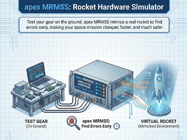
apex MRMSS is a smart simulator that ensures rocket experiments work perfectly. It bridges your lab and space, making every mission safer, cheaper, and easier.
 1. Introduction: Project Background and Purpose of the Paper
1.1 Research Background: MAPHEUS and the Reality of Microgravity Experiments The MORABA (Mobile Rocket Base) team at the German Aerospace Center (DLR) launches the MAPHEUS sounding rocket several times a year to perform actual flights. This rocket ascends to an altitude of over 100 km, providing a microgravity environment for approximately 6 minutes. Most developers creating the experimental equipment (Payload) to be mounted here are majors in biology or materials science, so their understanding of electronic/communication systems is relatively low. However, the equipment they create must be electrically and logically perfectly compatible with the rocket's brain, the Service Module (SM), during the actual launch for the mission to succeed.
1.2 Existing Problems: Limitations of the NI PXI System Previously, compatibility was tested using commercial Ground Support Equipment (GSE) based on National Instruments (NI) PXI chassis and LabVIEW. However, this had the following problems:
Cost Barrier: The system configuration cost reached thousands of Euros (tens of millions of KRW), making it difficult for small research teams with limited budgets to acquire.
Low Flexibility: Analog/Digital I/O cards were hardware-fixed to specific rocket interfaces, so it took a huge amount of time to reconfigure the equipment whenever starting a new project with a different pin-map.
1.3 Purpose of the Paper: Development and Application of the Core Solution 'MRMSS' The core theme of this paper is the direct fabrication and utilization of equipment called MRMSS (Multi-Role Mission Support System).
[ Definition and Role of MRMSS ] MRMSS is simulator equipment that allows for testing on the ground by perfectly assuming a situation where the actual experimental equipment (Rocket Payload) has ascended to space, without actually loading it onto a rocket and sending it to space.
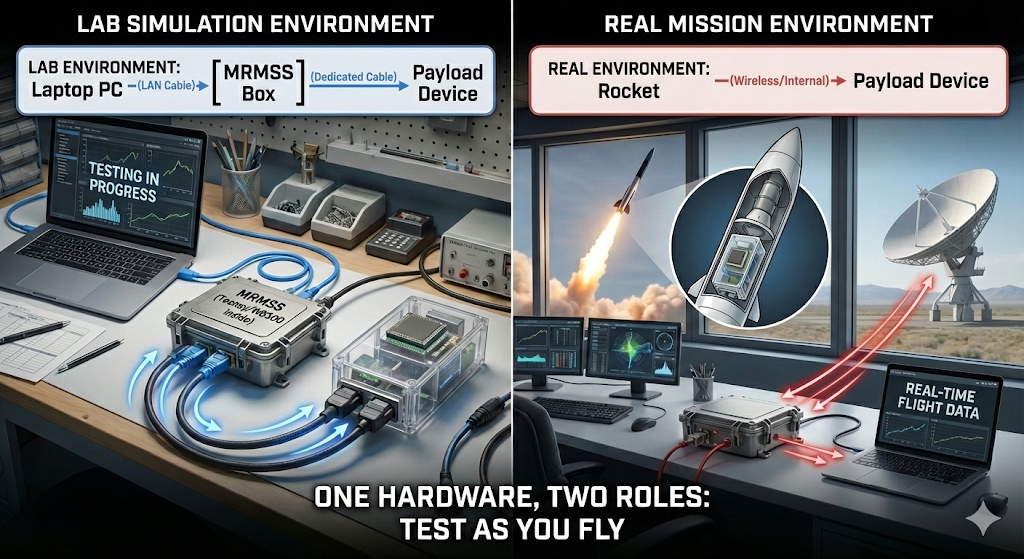
[ System Physical Connection Order ] The core configuration of this system is as follows: Laptop PC —(LAN Cable)—> [ MRMSS Box ] —(Dedicated Cable)—> Experimental Equipment (Payload)
This paper proposes an innovation by implementing this MRMSS inexpensively using Commercial Off-The-Shelf (COTS) components to perform the following two roles:
Cost Innovation: It replaces tens of millions of won worth of industrial equipment by implementing MRMSS with parts costing less than about 700,000 KRW ($500), such as Raspberry Pi, Teensy 4.1, and W5500.
Dual-Role Performance:
Laboratory Environment (Simulation Mode): Configured in the connection order above, MRMSS acts as a 'Fake Rocket'. It provides voltage and signals to the experimental equipment created by the researcher and pre-verifies whether it operates normally.
Actual Launch Environment (Ground Station Mode): After verification is complete, the MRMSS is taken as-is to the launch site. At this time, the simulation function is turned off, and it switches roles to a 'Ground Control System' that receives and monitors data sent by the rocket currently in flight.
Through this, the principle of "Test as you fly" is implemented to maximize system reliability.
2. Key Technical Elements and Selection Reasons (Methodology)
2.1 Key Technologies Used: Dualized MCU Design The MRMSS hardware is designed to allow the selection and mounting of one of two MCUs (Microcontrollers) depending on cost and performance requirements.
Option A (Standard): Teensy 4.1 (NXP i.MX RT1062)
Features: A high-performance processor of 600 MHz that communicates using the Native Ethernet controller built into the chip itself. (In this case, the W5500 chip is not used.)
Reason for Selection: Overwhelming processing speed allows for precise timing control, and it supports firmware encryption and code signing (Code Security) functions, making it suitable for space missions where security is important.
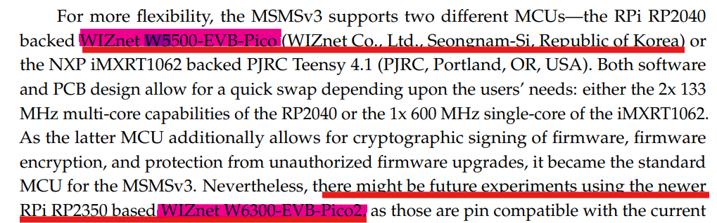
Option B (Alternative): WIZnet W5500-EVB-Pico (RP2040)
Features: Uses a module combining the inexpensive RP2040 chipset and the W5500 (Hardware TCP/IP chip).
Reason for Selection: The cost is very low and accessibility is good, and the W5500 chip handles network processing exclusively (Offloading) to support stable communication.
2.2 Software Stack
Docker-based Microservices: PC software runs on Docker containers, where Node-RED (Control UI), InfluxDB (Data Storage), and Python (Data Processing) are organically connected to provide the same environment regardless of the Operating System (OS).
3. In-depth Analysis of Hardware Operating Principles (Hardware Mechanics)
3.1 System Design Philosophy: "The Perfect Actor" MRMSS receives commands from the [Laptop] and provides an electrically perfect rocket environment to the [Experimental Equipment]. Physically, power, communication, and signal lines are all connected via a D-Sub 15-pin connector.
3.2 Signal Generation Control (Output): Rocket Sequence Simulation
Lift-off and Microgravity (SOE) Signals: The experimental equipment waits for specific electrical signals (triggers) sent by the rocket. MRMSS physically generates these signals using internal Open-Collector circuits and relays.
Operating Principle: When the researcher presses "Start Launch Sequence" on the laptop, the MCU (Teensy or Pico) switches the voltage to High/Low at precisely calculated timings to trick the experimental equipment.
3.3 Data Interface (Input/Output)
Switchable Termination: Resistance value requirements for communication lines (RS-422) differ for each rocket. MRMSS secures flexibility by equipping a relay circuit that can attach/detach a 120Ω termination resistor to the circuit via software settings alone, without needing to re-solder.
4. Communication Interface: The Role and Necessity of Ethernet
4.1 Technical Implementation: Differentiation of Communication Strategy by MCU The connection between the Laptop and the MRMSS Box is unified via Ethernet, but the internal implementation method differs depending on the selected MCU.
When using Teensy 4.1: Uses the high-performance Native Ethernet function built into the MCU. Since it communicates only through the PHY without a separate communication chip, data processing speed (Throughput) is very fast and latency is low.
When using W5500-EVB-Pico: Since the RP2040 lacks Ethernet function, the W5500 chip mounted on the board handles communication exclusively. The W5500 processes TCP/IP packet handling, checksum calculations, etc., in hardware, reducing the load on the MCU.
4.2 Necessity of Ethernet Adoption (Why Ethernet?)
Securing Safety Distance (Safety): Unlike USB cables (5m limit), Ethernet allows for long-distance connections of over 100m. When testing experimental equipment with explosion risks, researchers can control it from a safe Remote Office.
Data Highway: Even if the experimental equipment pours out thousands of data points per second, stable transmission and monitoring to the PC are possible via a gigabit network without the bandwidth limits of serial (USB).
5. Power Supply Design: Core Solutions for System Protection
5.1 Problem Statement: The Dangerous Cohabitation of 28V and 5V The experimental equipment (Payload) uses 28V high voltage, but the MRMSS control chip and laptop use 5V/3.3V. If a short circuit occurs inside the experimental equipment and 28V flows back through the communication line, there is a risk that all connected equipment will be destroyed.
5.2 Essential Solution: DPS and Electrical Isolation
Digital Power Supply (DPS): Ruideng's RK6006 module is mounted inside the MRMSS to precisely supply 28V power and immediately cut off upon overcurrent occurrence.
Optocoupler: An optocoupler is placed between the MCU, DPS, and external signal lines to transfer signals via 'Light' instead of electricity.
Effect: Even if an electrical explosion occurs on the experimental equipment side, the control unit (MCU) of the MRMSS and the laptop, which exchange signals via light, are physically separated and safely protected.
6. Firmware Function and Software Logic
6.1 Protocol Compatibility (CCSDS) MRMSS supports the CCSDS packet standard, which is the space data standard, at the firmware level. In other words, the data format exported by this equipment is 100% identical to the data sent by the actual rocket. Thanks to this, researchers can use the analysis software used during simulation as-is during the actual launch without modification.
6.2 Smart Automation (Auto-Sequence) Beyond simple manual control, full flight scenarios such as "T-0s Lift-off → T+74s Start Microgravity → T+400s Power Cut-off" can be uploaded to the firmware. MRMSS automatically executes this scenario using an internal timer to proceed with the experiment.
6.3 Future-Oriented Design: W6300 and RISC-V The paper suggests the W6300-EVB-Pico2 (RP2350 equipped) as a future upgrade path. Since this is compatible with the current 'Option B (Pico)' socket, it is designed so that the latest RISC-V architecture and Secure Boot functions can be introduced by simply replacing the module without changing the hardware.
1. 서론: 프로젝트 배경 및 논문의 목적
1.1 연구 배경: MAPHEUS와 미세중력 실험의 현실 독일 항공우주 센터(DLR)의 MORABA(Mobile Rocket Base) 팀은 연간 수차례 실제 비행을 수행하는 MAPHEUS 관측 로켓을 발사합니다. 이 로켓은 고도 100km 이상으로 상승하여 약 6분간의 미세중력(Microgravity) 환경을 제공합니다. 여기에 탑재되는 실험 장비(Payload)를 만드는 개발자들은 대부분 생물학, 재료공학 전공자로, 전자/통신 시스템에 대한 이해도가 상대적으로 낮습니다. 하지만 이들이 만든 장비는 실제 발사 시 로켓의 두뇌인 **서비스 모듈(Service Module, SM)**과 전기적/논리적으로 완벽하게 호환되어야만 임무에 성공할 수 있습니다.
1.2 기존 문제점: NI PXI 시스템의 한계 기존에는 National Instruments(NI)의 PXI 섀시와 LabVIEW 기반의 상용 지상 지원 장비(GSE)를 사용하여 호환성을 테스트했습니다. 하지만 이는 다음과 같은 문제가 있었습니다.
비용 장벽: 시스템 구성 비용이 **수천 유로(수천만 원)**에 달해 예산이 부족한 소규모 연구팀은 구비하기 어렵습니다.
낮은 유연성: 아날로그/디지털 I/O 카드가 특정 로켓 인터페이스에 맞게 하드웨어적으로 고정되어 있어, 핀맵(Pin-map)이 다른 새로운 프로젝트를 시작할 때마다 장비를 재구성하는 데 막대한 시간이 소요되었습니다.
1.3 논문의 목적: 핵심 솔루션 'MRMSS' 개발 및 적용 이 논문의 핵심 주제는 바로 **MRMSS (Multi-Role Mission Support System)**라는 장비를 직접 제작하고 활용하는 것입니다.
[ MRMSS의 정의와 역할 ] MRMSS는 실제 실험장비(로켓 페이로드)를 로켓에 실어 우주로 보내지 않고도, 지상에서 마치 우주로 올라간 상황을 완벽하게 가정하여 TEST를 할 수 있게 해주는 시뮬레이터 장비입니다.
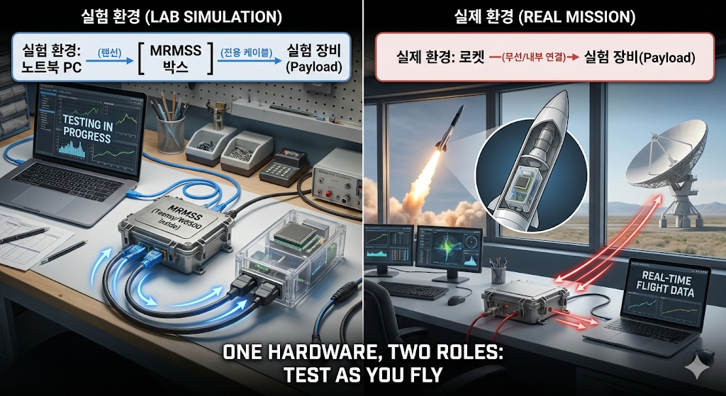
[ 시스템 물리적 연결 순서 ] 이 시스템의 핵심 구성은 다음과 같습니다: 노트북 PC —(랜선)—> [ MRMSS 박스 ] —(전용 케이블)—> 실험 장비(Payload)
본 논문은 이 MRMSS를 상용 기성품(COTS)으로 저렴하게 구현하여 다음 두 가지 역할을 수행하게 함으로써 혁신을 제안합니다.
비용 혁신: 수천만 원대 장비를 대체하여, Raspberry Pi, Teensy 4.1, W5500 등 약 70만 원 미만의 부품으로 MRMSS를 구현합니다.
이중 역할(Dual-Role) 수행:
실험실 환경 (Simulation Mode): 위 연결 순서대로 구성하여, MRMSS가 '가짜 로켓' 역할을 수행합니다. 연구자가 만든 실험 장비에 전압과 신호를 주며 정상 작동 여부를 사전 검증합니다.
실제 발사 환경 (Ground Station Mode): 검증이 끝나면 MRMSS를 그대로 발사장으로 가져갑니다. 이때는 시뮬레이션 기능을 끄고, 실제 비행 중인 로켓이 보내오는 데이터를 수신하는 **'지상 관제 시스템'**으로 사용합니다.
이를 통해 "Test as you fly (테스트했던 MRMSS 장비 그대로 실제 비행을 지원한다)" 원칙을 구현하여 시스템 신뢰성을 극대화합니다.
2. 핵심 기술 요소 및 선정 이유 (Methodology)
2.1 사용된 핵심 기술: 이원화된 MCU 설계 MRMSS 하드웨어는 비용과 성능 요구사항에 따라 두 가지 MCU(마이크로컨트롤러) 중 하나를 선택하여 장착할 수 있도록 설계되었습니다.
옵션 A (표준/Standard): Teensy 4.1 (NXP i.MX RT1062)
특징: 600MHz의 고성능 프로세서로, 칩 자체에 내장된 Native Ethernet 컨트롤러를 사용하여 통신합니다. (이 경우 W5500 칩은 사용하지 않습니다.)
선정 이유: 압도적인 처리 속도로 정밀한 타이밍 제어가 가능하며, 펌웨어 암호화 및 서명(Code Security) 기능을 지원하여 보안이 중요한 우주 임무에 적합합니다.
옵션 B (보급형/Alternative): WIZnet W5500-EVB-Pico (RP2040)
특징: 저렴한 RP2040 칩셋과 **W5500 (하드웨어 TCP/IP 칩)**이 결합된 모듈을 사용합니다.
선정 이유: 비용이 매우 저렴하고 접근성이 좋으며, 네트워크 처리를 W5500 칩이 전담(Offloading)하여 안정적인 통신을 지원합니다.
2.2 소프트웨어 스택
Docker 기반 마이크로 서비스: PC 소프트웨어는 Docker 컨테이너 위에서 구동되며, Node-RED(제어 UI), InfluxDB(데이터 저장), Python(데이터 처리)이 유기적으로 연결되어 운영체제(OS)에 상관없이 동일한 환경을 제공합니다.
3. 하드웨어 작동 원리 심층 분석 (Hardware Mechanics)
3.1 시스템 설계 철학: "완벽한 연기자" MRMSS는 **[노트북]**의 명령을 받아 **[실험 장비]**에게 전기적으로 완벽한 로켓 환경을 제공합니다. 물리적으로는 D-Sub 15핀 커넥터를 통해 전원, 통신, 신호선이 모두 연결됩니다.
3.2 신호 생성 제어 (Output): 로켓 시퀀스 모사
이륙(Lift-off) 및 무중력(SOE) 신호: 실험 장비는 로켓이 보내주는 특정 전기 신호(트리거)를 기다립니다. MRMSS는 내부의 오픈 컬렉터(Open-Collector) 회로와 릴레이를 사용하여 이 신호를 물리적으로 생성합니다.
동작 원리: 연구자가 노트북에서 "발사 시퀀스 시작"을 누르면, MCU(Teensy 또는 Pico)가 정확히 계산된 타이밍에 맞춰 전압을 High/Low로 전환하여 실험 장비를 속입니다.
3.3 데이터 인터페이스 (Input/Output)
가변 종단 저항 (Switchable Termination): 로켓마다 통신 선로(RS-422)의 저항값 요구사항이 다릅니다. MRMSS는 납땜을 다시 할 필요 없이, 소프트웨어 설정만으로 120Ω 종단 저항을 회로에 붙였다 뗐다 할 수 있는 릴레이 회로를 탑재하여 유연성을 확보했습니다.
4. 통신 인터페이스: 이더넷의 역할과 필연성
4.1 기술적 구현: MCU에 따른 통신 전략 차별화 노트북과 MRMSS 박스 사이의 연결은 **이더넷(Ethernet)**으로 통일되어 있지만, 내부 구현 방식은 선택한 MCU에 따라 다릅니다.
Teensy 4.1 사용 시: MCU에 내장된 고성능 Native Ethernet 기능을 사용합니다. 별도의 통신 칩 없이 PHY만 거쳐 통신하므로 데이터 처리 속도(Throughput)가 매우 빠르고 지연시간(Latency)이 적습니다.
W5500-EVB-Pico 사용 시: RP2040은 이더넷 기능이 없으므로, 보드에 장착된 W5500 칩이 통신을 전담합니다. W5500이 TCP/IP 패킷 처리, 체크섬 계산 등을 하드웨어적으로 처리해 주므로 MCU의 부하를 줄여줍니다.
4.2 이더넷 도입의 필수성 (Why Ethernet?)
안전 거리 확보 (Safety): USB 케이블(5m 한계)과 달리 이더넷은 100m 이상 장거리 연결이 가능합니다. 폭발 위험이 있는 실험 장비를 테스트할 때 연구원은 안전한 원격 사무실(Remote Office)에서 제어할 수 있습니다.
데이터 고속도로: 실험 장비가 초당 수천 개의 데이터를 쏟아내도 시리얼(USB) 대역폭 한계 없이 기가비트 네트워크를 통해 안정적으로 PC로 전송 및 모니터링이 가능합니다.
5. 전원 공급 설계: 시스템 보호를 위한 핵심 솔루션
5.1 문제 제기: 28V와 5V의 위험한 동거 실험 장비(Payload)는 28V 고전압을 쓰지만, MRMSS의 제어 칩과 노트북은 5V/3.3V를 씁니다. 실험 장비 내부 합선(Short)으로 28V가 통신선을 타고 역류하면 연결된 모든 장비가 전손될 위험이 있습니다.
5.2 필수 솔루션: DPS와 전기적 절연 (Isolation)
디지털 전원 장치 (DPS): Ruideng사의 RK6006 모듈을 MRMSS 내부에 장착하여, 28V 전원을 정밀하게 공급하고 과전류 발생 시 즉시 차단(Cut-off)합니다.
광커플러 (Optocoupler): MCU와 DPS, 그리고 외부 신호선 사이에 전기가 아닌 **'빛'**으로 신호를 전달하는 광커플러를 배치했습니다.
효과: 실험 장비 쪽에서 전기적 폭발이 일어나도, 빛으로 신호를 주고받는 MRMSS의 제어부(MCU)와 노트북은 물리적으로 분리되어 있어 안전하게 보호됩니다.
6. 펌웨어 기능 및 소프트웨어 로직
6.1 프로토콜 호환성 (CCSDS) MRMSS는 우주 데이터 표준인 CCSDS 패킷 규격을 펌웨어 레벨에서 지원합니다. 즉, 이 장비가 내보내는 데이터 형식은 실제 로켓이 보내는 데이터와 100% 동일합니다. 덕분에 연구원은 시뮬레이션 때 쓰던 분석 소프트웨어를 실제 발사 때도 수정 없이 그대로 사용할 수 있습니다.
6.2 스마트 오토메이션 (Auto-Sequence) 단순한 수동 제어를 넘어, "T-0초 이륙 → T+74초 무중력 시작 → T+400초 전원 차단"과 같은 전체 비행 시나리오를 펌웨어에 업로드할 수 있습니다. MRMSS는 내부 타이머를 이용해 이 시나리오를 자동으로 실행하며 실험을 진행합니다.
6.3 미래 지향적 설계: W6300과 RISC-V 논문은 향후 업그레이드 경로로 **W6300-EVB-Pico2 (RP2350 탑재)**를 제시합니다. 이는 현재의 '옵션 B(Pico)' 소켓과 호환되므로, 하드웨어 변경 없이 모듈만 교체하면 최신 RISC-V 아키텍처와 보안 부팅(Secure Boot) 기능을 도입할 수 있도록 설계되었습니다