



4-Door Access Control Panel with STM32G0 and W5500
.
KZQ_App — A Production-Grade 4-Door Access Controller Built on STM32G0 + W5500
#W5500 #TOE #UDP #STM32G0 #AccessControl #Wiegand #OTA #ioLibrary #IndustrialEthernet #EmbeddedSecurity
📚 Context: Commercial-style access control panel firmware (STM32CubeIDE project,
KZQ_App) Implementation status: Full application layer implemented and compiled — TCP command server, UDP discovery responder, PHY hot-plug recovery, 20,000-user database, 200,000-entry event log, and OTA staging over Ethernet are all present in source.
01 — What is this project?
Networked access control panels are one of the most demanding "small" embedded products in existence. A single controller has to simultaneously:
- decode four independent Wiegand reader channels in real time (bit-level ISR timing, no missed edges),
- evaluate an access decision against a 20,000-user credential database in single-digit milliseconds,
- keep an append-only audit log of 200,000 events that survives power loss,
- stay permanently reachable by a management server over TCP, and
- never, ever hang — a locked-up door controller is a physical security incident.
Most hobby-tier designs solve one of these. KZQ_App solves all five on a STM32G0B1VET6 — a Cortex-M0+ running at 64 MHz with no hardware TCP/IP MAC, no MMU, and no RTOS.
The enabling decision is the network stack. Instead of burning the M0+'s scarce RAM and cycles on a software TCP/IP stack, the design offloads the entire stack to a WIZnet W5500 over SPI2. What is left on the MCU is exactly what belongs there: Wiegand timing, access policy, and flash management.
The result is a bare-metal, super-loop firmware that behaves like a commercial panel:
| Capability | Scale |
|---|---|
| Wiegand reader channels | 4 (26-bit entry / 34-bit exit) |
| Doors controlled | up to 4 (single / dual / quad SKU via DOOR_TYPE) |
| User credential capacity | 20,000 |
| Event log capacity | 200,000 records × 16 B |
| Distinct event codes | 86 |
| External storage | W25Q128 (16 MB SPI NOR) |
| Firmware update | OTA staging area, 480 KB, delivered over TCP |
02 — Why hardware-offloaded Ethernet on a Cortex-M0+?
🔷 The M0+ simply does not have the budget for a software stack
An LwIP + MAC/PHY design on STM32 realistically wants tens of kilobytes of RAM for pbuf pools, TCP windows, and descriptor rings — plus a periodic timer thread and, in practice, an RTOS. The STM32G0B1 has 144 KB of RAM in total, and this firmware already spends it on Wiegand state machines, a 1040-byte protocol buffer, multi-card session state, and index build buffers. A software stack and this application cannot coexist comfortably on this part.
The W5500 removes the question entirely: TCP state machines, retransmission, window management, checksums and ARP all live inside the chip's own 32 KB of buffer memory. The MCU's involvement collapses to "read N bytes from socket 0."
🔷 The STM32G0 line has no Ethernet MAC at all
This is not a preference — it is a hard constraint. The STM32G0 series ships without an Ethernet peripheral. Adding wired Ethernet to a G0 means either abandoning the part for an F4/F7/H7 (higher cost, higher power, larger package, redesigned PCB) or adding a SPI-attached network controller. The W5500 keeps the entire design on a low-cost M0+.
🔷 Determinism is a safety property here, not a nice-to-have
In a door controller, a network stall must never delay a card read. With a software stack, a burst of traffic means a burst of CPU work in interrupt and timer context — exactly when a 26-bit Wiegand frame might be arriving with ~50 µs pulse timing. With the W5500, inbound traffic accumulates in the chip's buffer and is drained by the main loop when the firmware chooses to. network_process() sits in the super-loop next to readwiegand() and HAL_IWDG_Refresh() — network activity cannot preempt card decoding.
🔷 Position within the WIZnet ecosystem
The W5500 is the right member of the family for this board: it offers 8 hardware sockets (this design needs 2 concurrently, leaving 6 free for future services), a plain SPI interface that any MCU can drive, and an integrated PHY — no external magnetics-side PHY chip, no MII/RMII pin budget on a package that is already spending 14 GPIOs on Wiegand and SPI. Compared with an ENC28J60, the W5500 adds full hardware TCP/UDP offload rather than raw Ethernet framing (which would put LwIP right back into the M0+). Compared with a LAN8742A + MCU MAC, it removes the requirement for a MAC-equipped MCU entirely.
03 — System architecture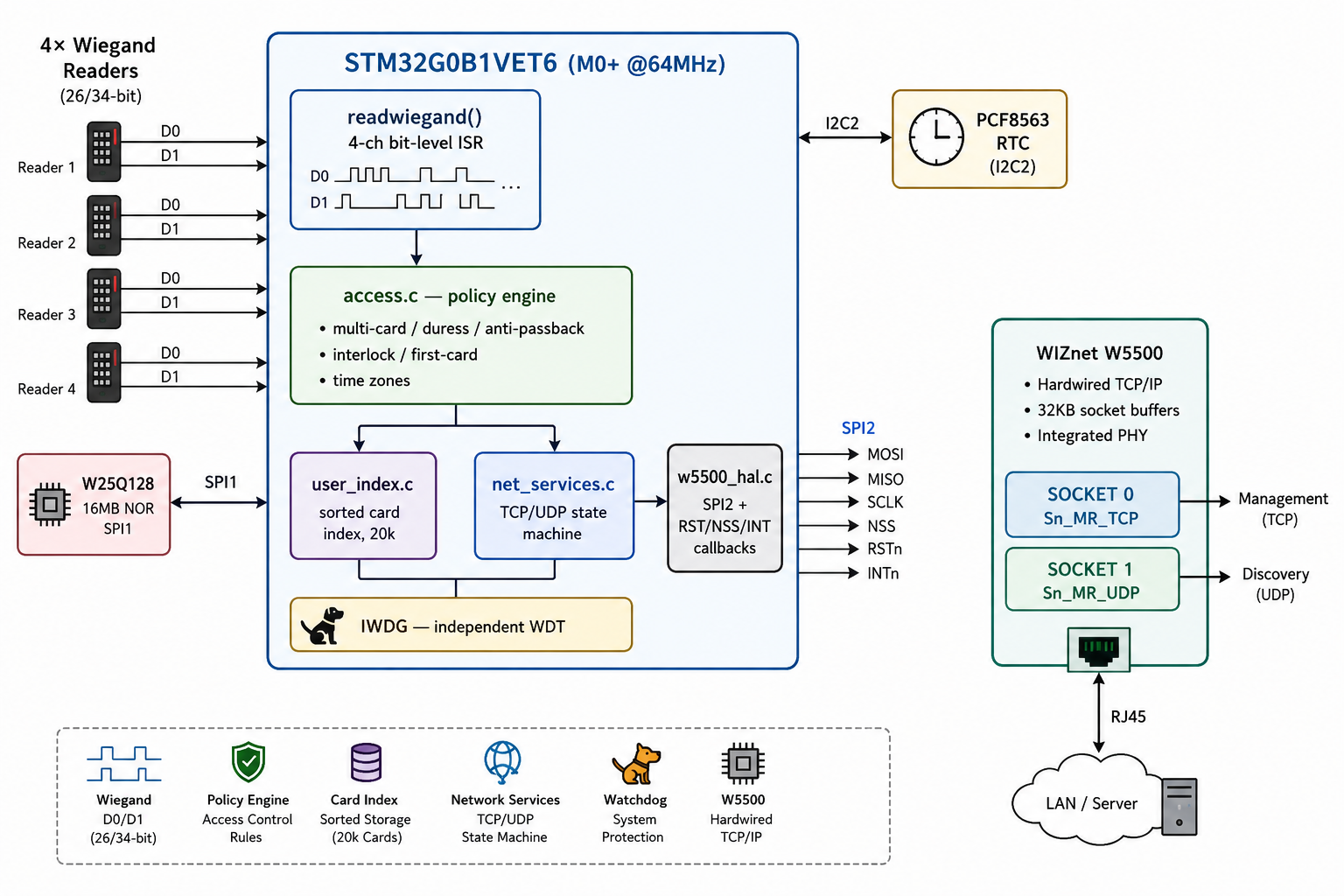 W25Q128 flash map (16 MB, fully partitioned):
0x000000 ┌──────────────────────────┐
         │ OTA staging area  480KB  │  ← firmware image received over TCP
0x078000 ├──────────────────────────┤
         │ System params / door     │
         │ params / weekly / holiday│
0x080000 ├──────────────────────────┤
         │ User table        3MB    │  ← 20,000 × 26B records
0x380000 ├──────────────────────────┤
         │ Anti-passback     512KB  │
0x400000 ├──────────────────────────┤
         │ Event log         3.2MB  │  ← 200,000 × 16B, circular
0x800000 ├──────────────────────────┤
         │ Log meta / card index    │
         └──────────────────────────┘
🧩 The eight building blocks, in plain terms
| # | Role | Block | What it actually does |
|---|---|---|---|
| 1 | Brain | STM32G0 microcontroller | A small, low-cost M0+ part with no Ethernet capability at all. No RTOS scheduler — everything runs from one continuously-spinning super-loop. |
| 2 | Eyes & ears | 4-channel Wiegand reader input | Accepts four card readers simultaneously. Reads the short electrical pulses a card produces in real time and converts them into a card number, distinguishing entry (short frame) from exit (long frame); keypad digits arrive the same way. |
| 3 | Judgment | Access policy engine | Decides "can this person open this door right now?" — not a simple allow/deny, but sequential multi-card requirements, duress cards/passwords for coercion situations, time-of-day restrictions, anti-passback (only someone recorded as "out" can go back "in"), and door interlocks that keep two doors from opening at once. |
| 4 | Memory | External bulk storage | The chip's own memory isn't nearly enough, so a separate 16 MB storage chip is attached. It holds 20,000 users' worth of card data, door configuration, 200,000 access-history records, and a staging area for incoming firmware — all partitioned separately. |
| 5 | Fast lookup | Background indexing | Scanning storage end-to-end to find one card among 20,000 would leave someone waiting at the reader. So a pre-sorted index is kept separately, and the heavy work of rebuilding that index is broken into small pieces processed in the background, without ever interrupting card recognition. |
| 6 | Clock | Battery-backed real-time clock chip | A separate chip that keeps time flowing even through a power loss. Weekly schedules, holiday schedules, and the timestamps on every access record all come from here. |
| 7 | Network | W5500 Ethernet chip | Every bit of communication — talking to the management server, being discoverable on an unfamiliar network, receiving remote commands — goes through this separate chip. The STM32G0 has no such capability on its own; this one chip solves it. |
| 8 | Watchdog | Independent watchdog timer | If the program ever hangs or falls into an infinite loop somewhere, this forces an automatic restart. A door controller can never be allowed to freeze up, so this safeguard is built in. |
Put together, the core idea of this project becomes clear: take a cheap chip that can't even do Ethernet on its own, hand off every specialized function to a dedicated external chip — networking to the W5500, storage to a separate flash, timekeeping to a separate RTC — and let the main chip focus on exactly one job: reading cards and making decisions. This division of labor is a large part of why the firmware holds up to commercial-product standards.
🛡 access.c — the access policy engine
This is where the project earns its "commercial-grade" label. Each door direction (4 doors × 2 directions = 8 independent contexts) carries its own fully independent rule set, and every card swipe is evaluated against all of the following before a relay ever fires:
- Per-card permission profile — each user record carries its own settings for which doors it may open, which unlock mode applies, and which schedule it follows; these are read as a block the moment a card is recognized.
- Configurable card-count unlock — a door can be set to open on a single swipe, or to require up to five cards presented in sequence before it releases.
- Card-plus-password mode — a swipe can be required to be followed by a PIN within a timeout window; failing to enter it in time silently resets the pending state.
- First-card enable — a door can be configured so that a designated "opening" card must be swiped once (e.g., by a supervisor arriving in the morning) before ordinary cards are accepted at all.
- Duress card and duress password — a separate credential unlocks the door normally while covertly signaling a duress alarm to the management server, so the person under threat shows no outward sign of distress.
- Master card and master password — a separate credential bypasses schedule and card-count rules entirely, functioning as an administrative override.
- Weekly + holiday scheduling — every credential is bound to a time-zone profile checked against both a weekly pattern and a separate holiday calendar, so access can differ between a regular Tuesday and a public holiday.
- Anti-passback — a per-user last-direction flag is persisted to flash and checked on every swipe, so a user who is recorded as "in" cannot swipe "in" again until an "out" is recorded — the standard defense against card cloning or tailgating.
- Door interlock — doors can be configured so that only one of a pair may be open at a time (an airlock pattern).
- Remote confirmation unlock — certain credentials do not unlock immediately; instead the controller sends a confirmation request to the management server over TCP and waits (with its own timeout) for explicit approval before releasing the door.
- Distinct rejection reasons — an unregistered card and a registered-but-unauthorized card are logged as two separate event types, rather than a single generic "denied."
Together these give the firmware a genuinely product-grade access policy vocabulary, not just an allow/deny card list.
04 — Why WIZnet W5500? ⭐
🔷 Socket mode: TOE TCP (Sn_MR_TCP) and hardware UDP (Sn_MR_UDP) running concurrently
This is the defining architectural choice of the project, and it is explicit in net_services.c:
#define TCP_SOCKET   0
#define UDP_SOCKET   1

socket(TCP_SOCKET, Sn_MR_TCP, sys_para.local_port, SF_IO_NONBLOCK);
listen(TCP_SOCKET);

socket(UDP_SOCKET, Sn_MR_UDP, sys_para.local_port, SF_IO_NONBLOCK);
Socket 0 runs in TOE (TCP Offload Engine) mode as a listening server for the management protocol — parameter read/write, user-table sync, log retrieval, remote unlock, time sync, OTA transfer. Every handshake, ACK, retransmission and window update is executed by the W5500's hardwired state machine; the M0+ never sees a TCP header.
Socket 1 runs in hardware UDP mode on the same port number, serving a device-discovery broadcast responder. When management software broadcasts an 11-byte magic frame, the controller replies with a 66-byte CRC-protected device descriptor — so a technician can find every panel on an unfamiliar LAN without knowing any IP address in advance.
This concurrent TCP+UDP arrangement is precisely what a hardware-socket architecture makes trivial and a software stack makes expensive. Two independent transport protocols, zero stack code, zero RAM cost on the MCU. Six sockets remain unused and available for future services.
🔷 Register-level control where it matters
The firmware does not stop at the BSD-style socket wrapper. Its receive path drives the W5500's socket registers directly:
uint16_t rx_rsr = getSn_RX_RSR(sn);      // bytes waiting in hardware buffer
wiz_recv_data(sn, buf, len);             // DMA-style burst read over SPI
setSn_CR(sn, Sn_CR_RECV);                // commit read pointer
while (getSn_CR(sn));                    // wait for command completion
if (getSn_IR(sn) & Sn_IR_RECV) setSn_IR(sn, Sn_IR_RECV);
getSn_RX_RSR() lets the super-loop poll for pending data with a single register read and skip the socket layer entirely when nothing has arrived — a meaningful saving when this check runs thousands of times per second alongside Wiegand decoding.
🔷 PHY link supervision → automatic recovery from cable events
Access panels live in ceilings and riser closets. Cables get unplugged, switches get rebooted, and nobody visits the device afterward. The firmware turns the W5500's PHY status into a first-class state machine input:
ctlwizchip(CW_GET_PHYLINK, &phy_link);
if (phy_link != phy_link_last) {
    if (phy_link == PHY_LINK_ON)  network_reinit();   // rebuild both sockets
    else { close(TCP_SOCKET); close(UDP_SOCKET); }    // release, wait
}
On link-up, both sockets are torn down and rebuilt from scratch, and the controller reports an EVENT_NET_RECOVER event to the server the moment the TCP session re-establishes — so the audit trail records the outage rather than silently swallowing it. This capability exists because the W5500 exposes real PHY state through CW_GET_PHYLINK; on a discrete PHY it would require a separate MDIO driver.
🔷 Robustness stack: non-blocking sockets + watchdog + explicit TCP states
The design layers three independent protections:
SF_IO_NONBLOCKon both sockets — no socket call can ever park the super-loop.- A 4-state TCP FSM (
IDLE → LISTEN → ESTABLISHED → CLOSING) with explicit handling ofSOCK_CLOSE_WAIT, unexpectedSOCK_CLOSED, and stale listening sockets — each path re-creates and re-listens rather than assuming recovery. HAL_IWDG_Refresh()in the same loop iteration asnetwork_process()— the independent watchdog is only fed if the network state machine returns.
Together these mean a network fault degrades to "door still works, reconnects on its own," which is the only acceptable failure mode for this product class.
🔷 Verified in-source evidence ✅
- ✅
w5500_hal.cregisters all four ioLibrary callback groups: CRIS (__disable_irq/__enable_irq), chip-select (PB12), byte SPI, and burst SPI - ✅ Hardware reset sequence on PA9 with 10 ms assert/release before
wizchip_init() - ✅ Socket buffers configured symmetrically:
{2,2,2,2,2,2,2,2}KB TX and RX — the full 16 KB / 16 KB - ✅ Static network configuration loaded from W25Q128 into
wiz_NetInfo(NETINFO_STATIC) - ✅ Application-layer heartbeat with configurable interval; send failure force-closes and re-listens
- ✅ Compiled object files for
w5500.o,socket.o,wizchip_conf.o,net_app.o,net_services.oare committed — the project builds
05 — Key components
🌐 WIZnet W5500 — TOE TCP (Sn_MR_TCP) + hardware UDP (Sn_MR_UDP), concurrent
Hardwired TCP/IP controller on SPI2. Socket 0 is a TOE TCP server for the management protocol; socket 1 is a hardware UDP responder for LAN discovery. Also supplies PHY link state via CW_GET_PHYLINK for hot-plug recovery. ioLibrary is vendored into Core/ethernet/ — the project is self-contained.
🎛 STM32G0B1VET6
Cortex-M0+ @ 64 MHz (HSE × PLLN 16 / P 2). Peripherals in use: SPI1 (NOR flash), SPI2 (W5500), I2C2 (RTC), USART1 with DMA, TIM2/TIM6, ADC1 (backup-battery voltage), IWDG. Vector table is relocated with SCB->VTOR = FLASH_BASE | 0x8000 — the application lives above a 32 KB bootloader.
💾 W25Q128 — 16 MB SPI NOR
Carries every persistent structure: OTA staging, system/door/schedule parameters, the 3 MB user table, anti-passback state, and the 3.2 MB circular event log.
🗂 user_index.c — sorted card-number index with background rebuild
The heart of the access latency story. A linear scan of 20,000 × 26-byte records across SPI NOR is far too slow to hold a reader waiting. Instead the firmware maintains an 8-byte-per-entry sorted index, built by an external merge sort (128-record chunks → 4 KB sorted runs → 512-entry merge output) that runs incrementally from the super-loop via UserIndex_Process(), so a 20,000-user rebuild never blocks card reads. Lookups go through UserIndex_FindUserByCard().
🔑 4-channel Wiegand front end
GPIO-interrupt bit capture on four independent D0/D1 pairs. 26-bit frames are treated as entry, 34-bit as exit; keypad digits, * and # arrive through the same channels for card+PIN and multi-card-plus-password flows.
⏰ PCF8563 RTC
Battery-backed timekeeping for weekly schedules, holiday programs and log timestamping, with a firmware Zeller's-congruence weekday calculation.
📡 Custom binary protocol over TCP
Framing: 0x53 header, 4-byte device UID, 16-bit little-endian length, CMD1/CMD2 opcode pair, payload, trailing CRC. Command groups cover parameters (0x02), OTA (0x04), remote unlock (0x08), time (0x09), user table (0x0A), door config (0x0B), weekly (0x0C) and holiday (0x0D) schedules, event log retrieval (0x0E, 0xF1) and anti-passback state (0x11). Every command is gated on a device-UID match derived from the STM32's unique ID, and payloads are XOR-masked with a UID-derived key — a lightweight device-binding layer that keeps a panel from accepting commands addressed to its neighbour.
06 — Application scenarios
01. Multi-tenant office buildings
Four readers, four doors, 20,000 credentials and weekly + holiday scheduling per door direction cover a full floor from a single panel. The server-side TCP session pushes credential updates without a site visit.
02. High-security rooms — multi-card and duress
The event map reserves codes for 1-through-5-card unlock sequences (EVENT_SINGLE_CARD … EVENT_QUINT_CARD), remote-verification unlock, and duress card/password paths that unlock the door while silently reporting an alarm event over the W5500 TCP session. Interlock codes prevent two doors in an airlock from being open at once.
03. Car parks and secure perimeters — anti-passback
A dedicated 512 KB flash region tracks in/out state per credential, with server-side commands to read, clear individual entries, or wipe the table — the standard remedy when a user tailgates and their state desynchronises.
04. Distributed sites — discovery + OTA
A technician on an unknown LAN broadcasts the discovery frame; every panel answers over UDP socket 1 with its identity and network configuration. Firmware updates are then streamed into the W25Q128's 480 KB staging area over TCP socket 0, with a reset command handing control to the bootloader — no on-site programmer, no opening the enclosure.
Conclusion
A Cortex-M0+ with no Ethernet MAC, running a bare-metal super-loop, delivers a four-door commercial access controller with 20,000 credentials, a 200,000-entry audit trail, LAN auto-discovery and field OTA — because the W5500 made the entire TCP/IP stack somebody else's problem.
- ✅ Concurrent TOE TCP + hardware UDP sockets on one SPI-attached W5500, zero stack RAM on the MCU
- ✅ Ethernet added to an STM32G0, a part with no Ethernet peripheral at all, with no move to a costlier F4/F7/H7
- ✅ PHY-link-driven automatic recovery with the outage recorded as an auditable event
- ✅ Register-level receive path (
getSn_RX_RSR/wiz_recv_data/Sn_CR_RECV) that stays out of the way of 4-channel Wiegand timing - ✅ Non-blocking sockets + explicit 4-state TCP FSM + IWDG — a network fault cannot stop a door
- ✅ 20,000-user lookup made real-time by a background-rebuilt external-merge-sort index
- ✅ 86-code event taxonomy covering duress, tamper, interlock, anti-passback, power and network events
- ✅ 480 KB OTA staging over TCP with UID-gated, XOR-masked commands
- ✅ ioLibrary vendored in-tree — the repository builds standalone in STM32CubeIDE
Q&A
Q. Why two sockets on the same port number — is that a conflict? No. TCP and UDP are separate transport namespaces, and the W5500 gives each socket its own independent hardware state machine and buffer. Socket 0 listens for TCP on local_port; socket 1 binds UDP on the same number. From the management software's point of view, one port number covers both discovery and control.
Q. Why not use MACRAW mode? MACRAW would hand the firmware raw Ethernet frames and require a software stack on top — the opposite of what this design needs. TOE TCP is chosen precisely so the M0+ never parses a header. MACRAW belongs in packet-analysis and L2-firewall projects; a door controller wants the offload.
Q. Six of eight sockets are idle. What could they be used for? Naturally: an HTTP configuration page, an MQTT uplink to a cloud back end, an SNTP client to replace manual time-sync, or a second management connection for a local touchscreen — each costing one socket and no additional stack RAM.
Q. How does the firmware avoid blocking on the network? Both sockets are opened with SF_IO_NONBLOCK, all socket work happens in one super-loop pass, and the independent watchdog is refreshed in the same iteration. If network_process() ever failed to return, the IWDG would reset the panel rather than leave it deaf.
Q. What happens if the cable is unplugged mid-transaction? check_phy_link() sees the transition, closes both sockets and stops. On re-link it calls network_reinit(), rebuilds TCP and UDP, and reports EVENT_NET_RECOVER upstream. Card reads, local unlock decisions and log writes continue throughout — the panel is designed to be fully functional offline and to reconcile on reconnection.
한글 버전
KZQ_App — STM32G0 + W5500으로 만든 상용급 4도어 출입통제 컨트롤러
#W5500 #TOE #UDP #STM32G0 #출입통제 #Wiegand #OTA #ioLibrary #산업용이더넷 #임베디드보안
📚 컨텍스트: 상용 출입통제 판넬 펌웨어 (STM32CubeIDE 프로젝트,
KZQ_App) 구현 상태: 애플리케이션 레이어 전체 구현 및 빌드 완료 — TCP 명령 서버, UDP 디스커버리 응답, PHY 핫플러그 복구, 2만 명 사용자 DB, 20만 건 이벤트 로그, 이더넷 OTA 스테이징이 모두 소스에 존재.
01 — 어떤 프로젝트인가?
네트워크 출입통제 판넬은 "작은" 임베디드 레벨에서 요구조건이 까다로운 부류에 속한다. 컨트롤러 한 대가 동시에 해내야 하는 일은 다음과 같다.
- 4채널 위건(Wiegand)리더를 실시간 디코딩 (비트 단위 ISR 타이밍, 엣지 누락 불가)
(Wiegand 리더는 벽이나 문 옆에 붙어있는, 카드를 갖다 대면 삑 소리 나면서 인식하는 장치) - 대규모 카드 DB를 조회해 한 자릿수 ms 안에 출입 판정
- 정전에도 살아남는 20만 건 감사 로그를 순차 기록
- 관리 서버와 TCP 세션을 상시 유지
- 그리고 절대 멈추지 않을 것 — 멈춘 도어 컨트롤러는 그 자체로 물리 보안 사고다.
취미 수준 설계이지만, KZQ_App은 다섯 가지를 전부 STM32G0B1VET6 위에서 푼다. 64 MHz Cortex-M0+, 이더넷 MAC 없음, MMU 없음, RTOS 없음인 부품이다.
이걸 가능하게 만든 결정이 네트워크 스택 선택이다. M0+의 귀한 RAM과 사이클을 소프트웨어 TCP/IP에 쓰는 대신, 스택 전체를 SPI2에 붙은 WIZnet W5500으로 오프로드했다. MCU에 남은 것은 딱 MCU가 해야 할 일 — Wiegand 타이밍, 출입 정책, 플래시 관리 — 뿐이다.
결과물은 상용 판넬처럼 동작하는 베어메탈 슈퍼루프 펌웨어다.
| 기능 | 규모 |
|---|---|
| Wiegand 리더 채널 | 4채널 (26비트 입실 / 34비트 퇴실) |
| 제어 도어 | 최대 4개 (DOOR_TYPE으로 1/2/4도어 SKU 구분) |
| 사용자 카드 용량 | 20,000명 |
| 이벤트 로그 용량 | 200,000건 × 16 B |
| 이벤트 코드 종류 | 86종 |
| 외부 저장장치 | W25Q128 (16 MB SPI NOR) |
| 펌웨어 업데이트 | TCP 전송 + 480 KB OTA 스테이징 영역 |
02 — 왜 Cortex-M0+에 하드웨어 오프로드 이더넷인가?
🔷 M0+에는 소프트웨어 스택을 돌릴 예산이 없다
STM32에서 LwIP + MAC/PHY 구성을 제대로 돌리려면 pbuf 풀, TCP 윈도우, 디스크립터 링에 수십 KB RAM이 필요하고, 주기 타이머 태스크와 사실상 RTOS가 따라붙는다. STM32G0B1의 전체 RAM은 144 KB이고, 이 펌웨어는 이미 그 공간을 Wiegand 상태머신, 1040바이트 프로토콜 버퍼, 다중카드 세션 상태, 인덱스 빌드 버퍼에 쓰고 있다. 이 부품에서 소프트웨어 스택과 이 애플리케이션은 편하게 공존할 수 없다.
W5500은 이 고민 자체를 없앤다. TCP 상태머신, 재전송, 윈도우 관리, 체크섬, ARP가 전부 칩 내부 32 KB 버퍼 메모리 안에서 처리된다. MCU가 할 일은 "소켓 0에서 N바이트 읽기"로 축소된다.
🔷 STM32G0 시리즈에는 이더넷 MAC이 아예 없다
이건 취향이 아니라 하드 제약이다. STM32G0에는 이더넷 페리페럴이 없다. G0에 유선 이더넷을 붙이려면 F4/F7/H7로 갈아타거나(원가·소비전력·패키지·PCB 전면 재설계) 아니면 SPI 방식 네트워크 컨트롤러를 붙이는 수밖에 없다. W5500은 설계 전체를 저가 M0+에 그대로 남겨준다.
🔷 여기서 결정성(determinism)은 부가 기능이 아니라 안전 속성이다
도어 컨트롤러에서 네트워크 지연이 카드 리딩을 밀어내면 안 된다. 소프트웨어 스택에서는 트래픽 폭주가 곧 인터럽트·타이머 컨텍스트의 CPU 부하 폭주인데, 하필 그 순간 26비트 Wiegand 프레임이 약 50 µs 펄스 타이밍으로 들어오고 있을 수 있다. W5500에서는 수신 트래픽이 칩 버퍼에 쌓여 있다가 펌웨어가 원하는 시점에 메인 루프가 꺼내간다. network_process()는 슈퍼루프 안에서 readwiegand(), HAL_IWDG_Refresh()와 나란히 놓여 있고, 네트워크 활동이 카드 디코딩을 선점할 방법이 없다.
🔷 WIZnet 생태계 안에서의 위치
이 보드에는 W5500이 정확히 맞는 선택이다. 하드웨어 소켓 8개(이 설계는 동시 2개만 쓰고 6개가 남는다), 어떤 MCU로도 구동 가능한 평범한 SPI 인터페이스, 그리고 PHY 내장 — 별도 PHY 칩도, MII/RMII 핀 예산도 필요 없다. 이미 Wiegand와 SPI에 14개 GPIO를 쓰고 있는 패키지에서 이건 결정적이다. ENC28J60 대비로는 생 이더넷 프레이밍이 아니라 완전한 TCP/UDP 하드웨어 오프로드를 제공한다(ENC28J60을 쓰면 LwIP가 M0+로 되돌아온다). LAN8742A + MCU MAC 조합 대비로는 MAC 내장 MCU라는 요구조건 자체를 없앤다.
03 — 시스템 아키텍처
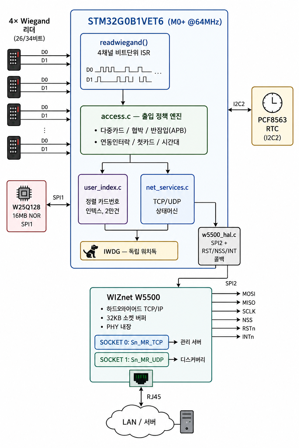
W25Q128 플래시 맵 (16 MB 전체 파티셔닝):
0x000000 ┌──────────────────────────┐
         │ OTA 스테이징 영역  480KB │  ← TCP로 수신한 펌웨어 이미지
0x078000 ├──────────────────────────┤
         │ 시스템/도어 파라미터,     │
         │ 주간·휴일 프로그램        │
0x080000 ├──────────────────────────┤
         │ 사용자 테이블      3MB   │  ← 20,000 × 26B 레코드
0x380000 ├──────────────────────────┤
         │ 반잠입(APB)       512KB  │
0x400000 ├──────────────────────────┤
         │ 이벤트 로그       3.2MB  │  ← 200,000 × 16B, 순환
0x800000 ├──────────────────────────┤
         │ 로그 메타 / 카드 인덱스   │
         └──────────────────────────┘
🧩 이 프로젝트를 구성하는 여덟 가지
| # | 역할 | 구성요소 | 실제로 하는 일 |
|---|---|---|---|
| 1 | 두뇌 | STM32G0 마이크로컨트롤러 | 이더넷 기능이 아예 없는, 저렴하고 작은 M0+급 칩. RTOS(운영체제급 스케줄러) 없이 그냥 계속 돌아가는 반복문(슈퍼루프) 하나로 모든 걸 처리한다. |
| 2 | 눈과 귀 | 4채널 Wiegand 리더 입력 | 카드리더 4대를 동시에 받는다. 카드를 대면 들어오는 짧은 전기 신호를 실시간으로 읽어서 카드번호로 변환하고, 입실용(짧은 신호)과 퇴실용(긴 신호)을 구분해서 처리한다. 숫자 키패드 입력도 같은 방식으로 받는다. |
| 3 | 판단 | 출입 정책 엔진 | 카드를 읽고 나면 "이 사람이 이 문을 지금 열어도 되는가"를 판단한다. 단순 허용/거부가 아니라, 여러 장 카드를 순서대로 대야 열리는 경우, 협박(강요) 상황에서 쓰는 특수 카드나 비밀번호, 시간대별 출입 제한, 나간 사람만 다시 들어올 수 있게 하는 반잠입 방지, 문 두 개가 동시에 열리면 안 되는 연동 제한 같은 걸 다 관리한다. |
| 4 | 기억 | 외장 대용량 저장장치 | 칩 자체 메모리로는 어림도 없어서, 16메가바이트짜리 별도 저장 칩을 하나 더 달았다. 여기에 2만 명 분량의 카드 정보, 도어 설정값, 출입 이력 20만 건, 그리고 새 펌웨어를 임시로 받아두는 공간까지 전부 나눠서 저장한다. |
| 5 | 빠른 찾기 | 배경 인덱스 작업 | 2만 명 중에 카드 한 장을 찾으려고 저장장치를 처음부터 끝까지 뒤지면 사람이 리더 앞에서 한참 기다려야 한다. 그래서 미리 정렬해둔 색인을 따로 만들어두고, 이 색인을 새로 만드는 무거운 작업은 카드 인식을 방해하지 않게 조금씩 나눠서 틈틈이 백그라운드로 처리한다. |
| 6 | 시계 | 배터리 백업 실시간 시계 칩 | 전원이 나가도 시간이 계속 흐르게 해주는 별도 칩. 주간 스케줄, 휴일 스케줄, 출입 기록에 찍히는 시각이 여기서 나온다. |
| 7 | 네트워크 | W5500 이더넷 칩 | 컨트롤러가 관리 서버와 대화하고, 낯선 네트워크에서도 발견되고, 원격으로 명령을 받는 모든 통신이 이 별도 칩을 통해 이뤄진다. 원래 STM32G0에는 이 기능이 없는데, 이 칩 하나 붙여서 해결했다. |
| 8 | 감시자 | 워치독 | 프로그램이 어딘가에서 멈추거나 무한 루프에 빠지면 자동으로 강제 재시작시키는 장치. 도어 컨트롤러는 절대 먹통이 되면 안 되니까 이런 안전장치가 들어가 있다. |
이 여덟 가지를 합쳐놓고 보면 이 프로젝트의 핵심 아이디어가 뚜렷해진다. 원래 이더넷도 못 다루는 저가형 칩 하나에, 필요한 기능을 전부 외부 전문 칩(네트워크는 W5500, 저장은 별도 플래시, 시계는 별도 RTC)에 나눠 맡기고, 메인 칩은 오직 "카드 읽고 판단하기"에만 집중하게 만든 구조다. 이런 식의 역할 분담이 이 펌웨어를 상용 제품 수준으로 만들어주는 핵심 이유다.
🛡 access.c — 출입 정책 엔진
이 프로젝트가 "상용급"이라는 이름값을 하는 지점이다. 도어 4개 × 방향 2개, 총 8개의 독립된 문맥마다 완전히 별개의 규칙 집합을 가지고 있고, 카드를 대는 순간부터 실제로 문이 열리기까지 다음 항목들을 전부 통과해야 한다.
- 카드별 권한 프로필 — 카드마다 어느 문을 열 수 있는지, 어떤 개문 방식을 따르는지, 어떤 스케줄을 적용받는지가 개별적으로 저장되어 있고, 카드를 인식하는 순간 한 번에 통째로 읽어온다.
- 카드 매수 설정형 개문 — 한 장만 대면 열리게 할 수도, 최대 다섯 장을 순서대로 대야 열리게 할 수도 있다.
- 카드+비밀번호 조합 모드 — 카드를 댄 뒤 정해진 시간 안에 비밀번호를 입력해야 열리도록 강제할 수 있다. 시간 안에 입력하지 못하면 대기 상태가 조용히 초기화된다.
- 첫 카드(개문) 활성화 — 지정된 "개문 카드"(예: 아침에 출근한 관리자)가 한 번 먼저 인식되어야 그 뒤로 일반 카드들이 받아들여지도록 설정할 수 있다.
- 협박(강요) 카드 / 협박 비밀번호 — 별도의 카드로 문은 정상적으로 열어주면서, 뒤에서는 관리 서버에 조용히 협박 경보를 보낸다. 협박받는 당사자가 겉으로 티를 내지 않아도 된다.
- 슈퍼(마스터) 카드 / 슈퍼 비밀번호 — 스케줄 제한이나 카드 매수 조건을 전부 건너뛰고 무조건 여는 별도 인증 수단으로, 관리자 비상용 오버라이드 역할을 한다.
- 주간 + 공휴일 스케줄 — 모든 카드는 요일별 시간대 규칙과 별도의 공휴일 달력을 동시에 검사받는다. 평범한 화요일과 공휴일에 다른 규칙을 적용할 수 있다.
- 반잠입 방지(Anti-passback) — 사용자별로 마지막에 어느 방향으로 지나갔는지를 플래시에 저장해두고 매 출입마다 확인한다. "들어간" 상태로 기록된 사람은 "나감"이 기록되기 전까지 다시 "들어감"으로 처리되지 않는다 — 카드 복제나 꼬리물기를 막는 표준적인 방어 방식이다.
- 문 간 연동 제한(인터락) — 한 쌍의 문 중 하나만 열려 있을 수 있게(에어락 방식) 설정할 수 있다.
- 원격 확인 후 개문 — 특정 카드는 즉시 열리지 않고, 컨트롤러가 관리 서버에 TCP로 확인 요청을 보낸 뒤 자체 타임아웃 안에 명시적인 승인이 와야만 문을 연다.
- 거부 사유의 구분 기록 — 등록되지 않은 카드와, 등록은 되어 있지만 이 문에는 권한이 없는 카드를 하나의 "거부" 이벤트가 아니라 서로 다른 이벤트 종류로 구분해서 기록한다.
이 항목들이 합쳐져서, 이 펌웨어는 단순한 허용/거부 카드 목록이 아니라 실제 상용 제품 수준의 출입 정책 어휘를 갖추고 있다.
04 — 왜 WIZnet W5500인가? 코드 분석 ⭐
🔷 사용 모드: TOE TCP(Sn_MR_TCP)와 하드웨어 UDP(Sn_MR_UDP) 동시 운용
이 프로젝트를 규정하는 아키텍처 선택이고, net_services.c에 명시적으로 드러난다.
#define TCP_SOCKET   0
#define UDP_SOCKET   1

socket(TCP_SOCKET, Sn_MR_TCP, sys_para.local_port, SF_IO_NONBLOCK);
listen(TCP_SOCKET);

socket(UDP_SOCKET, Sn_MR_UDP, sys_para.local_port, SF_IO_NONBLOCK);
소켓 0은 TOE(TCP Offload Engine) 모드로, 관리 프로토콜용 리스닝 서버다 — 파라미터 읽기/쓰기, 사용자 테이블 동기화, 로그 회수, 원격 개문, 시각 동기화, OTA 전송. 핸드셰이크, ACK, 재전송, 윈도우 갱신은 전부 W5500의 하드와이어드 상태머신이 처리하고, M0+는 TCP 헤더를 구경조차 하지 않는다.
소켓 1은 하드웨어 UDP 모드로 같은 포트 번호에 바인딩되어 장치 탐색 브로드캐스트에 응답한다. 관리 소프트웨어가 11바이트 매직 프레임을 브로드캐스트하면, 컨트롤러는 CRC가 붙은 66바이트 장치 정보로 답한다. 덕분에 IP를 하나도 모르는 낯선 LAN에서도 기술자가 모든 판넬을 찾아낼 수 있다.
TCP + UDP 동시 운용은 하드웨어 소켓 아키텍처에서는 거저 얻어지고 소프트웨어 스택에서는 비싸게 치러야 하는 바로 그 지점이다. 독립적인 두 전송 프로토콜, 스택 코드 0줄, MCU RAM 소모 0. 남은 6개 소켓은 언제든 확장에 쓸 수 있다.
🔷 필요한 곳에서는 레지스터 레벨 제어
이 펌웨어는 BSD 스타일 소켓 래퍼에서 멈추지 않는다. 수신 경로는 W5500 소켓 레지스터를 직접 다룬다.
uint16_t rx_rsr = getSn_RX_RSR(sn);      // 하드웨어 버퍼에 대기 중인 바이트 수
wiz_recv_data(sn, buf, len);             // SPI 버스트 읽기
setSn_CR(sn, Sn_CR_RECV);                // 읽기 포인터 커밋
while (getSn_CR(sn));                    // 명령 완료 대기
if (getSn_IR(sn) & Sn_IR_RECV) setSn_IR(sn, Sn_IR_RECV);
getSn_RX_RSR() 덕분에 슈퍼루프는 레지스터 1회 읽기로 수신 대기 여부를 판단하고, 데이터가 없으면 소켓 레이어를 통째로 건너뛴다. 초당 수천 번 도는 루프에서 Wiegand 디코딩과 시간을 나눠 써야 하는 상황이라면 의미 있는 절약이다.
🔷 PHY 링크 감시 → 케이블 이벤트 자동 복구
출입 판넬은 천장과 통신 랙 안에 산다. 케이블은 빠지고 스위치는 리부팅되며, 그 뒤에 아무도 찾아오지 않는다. 이 펌웨어는 W5500의 PHY 상태를 상태머신의 1급 입력으로 취급한다.
ctlwizchip(CW_GET_PHYLINK, &phy_link);
if (phy_link != phy_link_last) {
    if (phy_link == PHY_LINK_ON)  network_reinit();   // 두 소켓 재구성
    else { close(TCP_SOCKET); close(UDP_SOCKET); }    // 정리 후 대기
}
링크가 살아나면 두 소켓을 완전히 헐고 다시 세우며, TCP 세션이 재수립되는 순간 EVENT_NET_RECOVER 이벤트를 서버로 보고한다. 단절을 조용히 삼키는 대신 감사 로그에 남기는 것이다. 이 기능이 가능한 이유는 W5500이 CW_GET_PHYLINK로 실제 PHY 상태를 노출하기 때문이며, 외장 PHY였다면 별도 MDIO 드라이버가 필요했을 일이다.
🔷 견고성 3중 구조: 논블로킹 소켓 + 워치독 + 명시적 TCP 상태
설계는 서로 독립적인 세 겹의 보호를 쌓았다.
- 두 소켓 모두
SF_IO_NONBLOCK— 어떤 소켓 호출도 슈퍼루프를 붙잡지 못한다. - 4상태 TCP FSM (
IDLE → LISTEN → ESTABLISHED → CLOSING) —SOCK_CLOSE_WAIT, 예기치 못한SOCK_CLOSED, 죽은 리스닝 소켓을 각각 명시적으로 처리하고, 모든 경로가 "알아서 낫겠지"가 아니라 소켓 재생성 + 재리슨으로 끝난다. HAL_IWDG_Refresh()가network_process()와 같은 루프 반복 안에 있다 — 네트워크 상태머신이 리턴해야만 워치독이 먹인다.
이 셋이 합쳐져, 네트워크 장애는 "문은 계속 열리고, 네트워크는 알아서 복구된다"로 격하된다. 이 제품군에서 허용되는 유일한 실패 모드다.
🔷 소스에서 확인된 근거 ✅
- ✅
w5500_hal.c가 ioLibrary 콜백 4종을 모두 등록: CRIS(__disable_irq/__enable_irq), 칩셀렉트(PB12), 바이트 SPI, 버스트 SPI - ✅
wizchip_init()전 PA9 하드웨어 리셋 시퀀스 (10 ms assert/release) - ✅ 소켓 버퍼 대칭 구성: TX/RX 각각
{2,2,2,2,2,2,2,2}KB — 16 KB / 16 KB 전량 사용 - ✅ W25Q128에서 읽어온 정적 네트워크 설정을
wiz_NetInfo로 반영 (NETINFO_STATIC) - ✅ 주기 설정 가능한 애플리케이션 레벨 하트비트, 전송 실패 시 강제 종료 후 재리슨
- ✅
w5500.o,socket.o,wizchip_conf.o,net_app.o,net_services.o오브젝트 파일이 커밋되어 있음 — 빌드가 통과한 프로젝트
05 — 핵심 구성요소
🌐 WIZnet W5500 — TOE TCP(Sn_MR_TCP) + 하드웨어 UDP(Sn_MR_UDP) 동시 사용
SPI2에 연결된 하드와이어드 TCP/IP 컨트롤러. 소켓 0은 관리 프로토콜용 TOE TCP 서버, 소켓 1은 LAN 탐색용 하드웨어 UDP 응답기. CW_GET_PHYLINK로 PHY 링크 상태까지 공급해 핫플러그 복구를 가능하게 한다. ioLibrary는 Core/ethernet/에 함께 포함되어 있어 프로젝트가 자체 완결된다.
🎛 STM32G0B1VET6
Cortex-M0+ @ 64 MHz (HSE × PLLN 16 / P 2). 사용 페리페럴: SPI1(NOR 플래시), SPI2(W5500), I2C2(RTC), DMA 연동 USART1, TIM2/TIM6, ADC1(예비전원 전압), IWDG. SCB->VTOR = FLASH_BASE | 0x8000으로 벡터테이블을 재배치 — 32 KB 부트로더 위에 애플리케이션이 올라간다.
💾 W25Q128 — 16 MB SPI NOR
모든 영속 데이터의 집. OTA 스테이징, 시스템/도어/스케줄 파라미터, 3 MB 사용자 테이블, 반잠입 상태, 3.2 MB 순환 이벤트 로그.
🗂 user_index.c — 정렬 카드번호 인덱스 + 백그라운드 재구축
출입 응답속도의 핵심. 20,000 × 26바이트 레코드를 SPI NOR에서 선형 스캔하면 리더 앞에 선 사람을 기다리게 만든다. 대신 엔트리당 8바이트 정렬 인덱스를 유지하며, 외부 병합 정렬(128레코드 청크 → 4 KB 정렬 런 → 512엔트리 병합 출력)로 만든다. 이 작업은 UserIndex_Process()를 통해 슈퍼루프에서 조금씩 나눠 수행되므로, 2만 명 인덱스를 다시 만드는 동안에도 카드 리딩이 멈추지 않는다. 조회는 UserIndex_FindUserByCard().
🔑 4채널 Wiegand 프론트엔드
독립된 D0/D1 쌍 4조에 대한 GPIO 인터럽트 비트 캡처. 26비트 프레임은 입실, 34비트는 퇴실로 처리하고, 키패드 숫자와 */#도 같은 채널로 들어와 카드+비밀번호, 다중카드+비밀번호 시나리오를 지원한다.
⏰ PCF8563 RTC
배터리 백업 시계. 주간 스케줄, 휴일 프로그램, 로그 타임스탬프에 사용되며 요일은 펌웨어에서 젤러 공식으로 계산한다.
📡 TCP 기반 커스텀 바이너리 프로토콜
프레이밍: 0x53 헤더, 4바이트 장치 UID, 16비트 리틀엔디언 길이, CMD1/CMD2 오피코드 쌍, 페이로드, 말미 CRC. 명령군은 파라미터(0x02), OTA(0x04), 원격 개문(0x08), 시각(0x09), 사용자 테이블(0x0A), 도어 설정(0x0B), 주간(0x0C)·휴일(0x0D) 스케줄, 이벤트 로그 회수(0x0E, 0xF1), 반잠입 상태(0x11)를 포괄한다. 모든 명령은 STM32 고유 ID에서 파생한 장치 UID 일치를 통과해야 하고, 페이로드는 같은 UID에서 만든 키로 XOR 마스킹된다 — 옆 판넬로 갈 명령을 받아 실행하지 않게 만드는 경량 장치 바인딩 계층이다.
06 — 응용 시나리오
01. 다중 임차 오피스 빌딩
리더 4채널, 도어 4개, 2만 명 카드, 도어 방향별 주간+휴일 스케줄이면 판넬 한 대로 한 개 층을 커버한다. 카드 등록/삭제는 서버 TCP 세션으로 밀어넣으니 현장 방문이 필요 없다.
02. 고보안 구역 — 다중카드와 협박 대응
이벤트 맵에는 1~5장 카드 조합 개문(EVENT_SINGLE_CARD … EVENT_QUINT_CARD), 원격 확인 개문, 그리고 협박 카드/비밀번호 경로가 예약되어 있다. 협박 경로는 문은 정상적으로 열어주면서 W5500 TCP 세션으로 조용히 경보 이벤트를 보고한다. 인터락 코드는 에어락 구조에서 두 문이 동시에 열리는 것을 막는다.
03. 주차장·보안 경계 — 반잠입(Anti-passback)
전용 512 KB 플래시 영역이 카드별 입/출 상태를 추적하고, 서버 명령으로 조회·개별 삭제·전체 초기화가 가능하다. 꼬리물기로 상태가 어긋난 사용자를 푸는 표준 처방이다.
04. 분산 현장 — 디스커버리 + OTA
IP를 모르는 현장에서 기술자가 탐색 프레임을 브로드캐스트하면, 모든 판넬이 UDP 소켓 1로 자기 신원과 네트워크 설정을 답한다. 이후 펌웨어는 TCP 소켓 0을 통해 W25Q128의 480 KB 스테이징 영역으로 스트리밍되고, 리셋 명령으로 부트로더에 제어를 넘긴다. 현장 프로그래머도, 함체 개방도 필요 없다.
결론
이더넷 MAC조차 없는 Cortex-M0+가, RTOS도 없는 베어메탈 슈퍼루프로, 2만 명 카드와 20만 건 감사 로그와 LAN 자동 탐색과 현장 OTA를 갖춘 4도어 상용 출입통제기를 완성했다. W5500이 TCP/IP 스택 전체를 남의 일로 만들어줬기 때문이다.
- ✅ SPI에 붙은 W5500 하나로 TOE TCP + 하드웨어 UDP 동시 운용, MCU 스택 RAM 소모 0
- ✅ 이더넷 페리페럴이 아예 없는 STM32G0에 유선 이더넷 구현, 비싼 F4/F7/H7로 갈아타지 않고
- ✅ PHY 링크 기반 자동 복구, 그리고 단절을 감사 가능한 이벤트로 기록
- ✅ 4채널 Wiegand 타이밍을 방해하지 않는 레지스터 레벨 수신 경로(
getSn_RX_RSR/wiz_recv_data/Sn_CR_RECV) - ✅ 논블로킹 소켓 + 명시적 4상태 TCP FSM + IWDG — 네트워크 장애가 문을 멈추지 못한다
- ✅ 백그라운드 외부 병합 정렬 인덱스로 2만 명 조회를 실시간화
- ✅ 협박·방탈·인터락·반잠입·전원·네트워크를 아우르는 86종 이벤트 체계
- ✅ UID 인증 + XOR 마스킹 명령 위에 올린 480 KB TCP OTA
- ✅ ioLibrary 인트리 포함 — STM32CubeIDE에서 단독 빌드 가능
Q&A
Q. 두 소켓이 같은 포트 번호를 쓰는데 충돌 아닌가? 아니다. TCP와 UDP는 서로 다른 전송 계층 네임스페이스이고, W5500은 소켓마다 독립적인 하드웨어 상태머신과 버퍼를 준다. 소켓 0은 local_port에서 TCP 리슨, 소켓 1은 같은 번호로 UDP 바인딩. 관리 소프트웨어 입장에서는 포트 번호 하나로 탐색과 제어가 모두 해결된다.
Q. 왜 MACRAW 모드를 쓰지 않았나? MACRAW는 생 이더넷 프레임을 펌웨어에 넘기고 그 위에 소프트웨어 스택을 요구한다 — 이 설계가 원하는 것의 정반대다. TOE TCP를 고른 이유가 바로 M0+가 헤더를 파싱하지 않게 하기 위함이다. MACRAW는 패킷 분석기나 L2 방화벽 프로젝트의 영역이고, 도어 컨트롤러가 원하는 건 오프로드다.
Q. 8개 소켓 중 6개가 놀고 있다. 뭘 더 할 수 있나? 자연스러운 확장으로는 HTTP 설정 페이지, 클라우드 백엔드로의 MQTT 업링크, 수동 시각 동기화를 대체할 SNTP 클라이언트, 로컬 터치스크린용 두 번째 관리 커넥션 등이 있다. 각각 소켓 하나만 쓰고 추가 스택 RAM은 들지 않는다.
Q. 네트워크에서 블로킹되지 않는 것은 어떻게 보장하나? 두 소켓 모두 SF_IO_NONBLOCK으로 열리고, 모든 소켓 작업이 슈퍼루프 한 번에 처리되며, 독립 워치독이 같은 반복 안에서 갱신된다. network_process()가 리턴하지 못하는 상황이 오면 IWDG가 판넬을 리셋한다 — 먹통인 채로 방치되지 않는다.
Q. 트랜잭션 도중 케이블이 뽑히면? check_phy_link()가 전이를 감지해 두 소켓을 닫고 대기한다. 링크가 복구되면 network_reinit()이 TCP/UDP를 재구성하고 EVENT_NET_RECOVER를 상위로 보고한다. 그 사이에도 카드 리딩, 로컬 개문 판정, 로그 기록은 계속된다 — 이 판넬은 오프라인에서 완전히 동작하고 재접속 시 정합을 맞추도록 설계되어 있다.