
ioNIC Loopback Arduino Guide
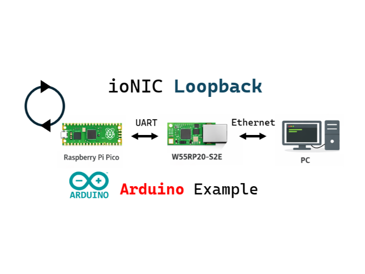
This guide explains how to control the W55RP20-S2E module using a Raspberry Pi Pico and implement network loopback functionality.

Raspberry Pi - Raspberry Pi Pico
x 1

Arduino - Arduino IDE
x 1
How to Run Loopback Example
This project uses the Raspberry Pi Pico as the main controller to operate the W55RP20-S2E module. Connect to the W55RP20-S2E module via SPI or UART communication to implement TCP Client, TCP Server, and UDP Loopback functionality.
Supported Communication Methods:
- SPI Communication
- UART Communication
Supported Loopback Modes:
- TCP Client Loopback
- TCP Server Loopback
- UDP Loopback
Step 1: Prepare Software
Download and install the following software:
Required Software:
Step 2: Hardware Connections
2.1 SPI Mode Connection
When controlling the W55RP20-S2E module via SPI, connect as follows:
| Raspberry Pi Pico | W55RP20-S2E Module | Description |
|---|---|---|
| GP4 (SPI0 RX/MISO) | GP3 (SPI_MISO) | Master In Slave Out |
| GP3 (SPI0 TX/MOSI) | GP4 (SPI_MOSI) | Master Out Slave In |
| GP2 (SPI0 SCK) | GP2 (SPI_SCK) | Clock Signal |
| GP5 (SPI0 CSn) | GP5 (SPI_CSn) | Chip Select |
| GP13 | GP13 (SPI_INT) | SPI Master Recv data pending pin |
| GP26 | GP26 (UART_SPI_SEL) | UART/SPI interface select pin (High:SPI, Low/NC:UART) |
| 3.3V | 3V3 | Power Supply |
| GND | GND | Ground |
2.2 UART Mode Connection
When controlling the W55RP20-S2E module via UART:
| Raspberry Pi Pico | W55RP20-S2E Module | Description |
|---|---|---|
| GP4 (UART1 TX) | GP5 (UART1 RX) | Pico TX → Module RX |
| GP5 (UART1 RX) | GP4 (UART1 TX) | Pico RX → Module TX |
| GND | GND | Ground |
| 3.3V | VCC/3V3 | Power Supply |
Step 3: Arduino IDE Setup
Install Board Support Package
- Open Arduino IDE
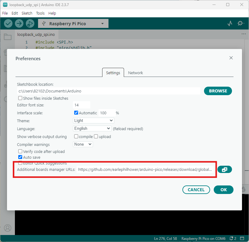
- Go to File → Preferences
- Add the following to "Additional Boards Manager URLs": https://github.com/earlephilhower/arduino-pico/releases/download/global/package_rp2040_index.json
- Go to Tools → Board → Boards Manager
- Search for "Raspberry Pi Pico" and install Raspberry Pi Pico/RP2040 by Earle F. Philhower, III
- Select Tools → Board → Raspberry Pi RP2040 Boards → Raspberry Pi Pico
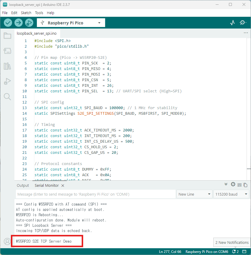
Step 4: Code Examples
Each example provides a .ino file to upload to the Pico.
- SPI Communication
2. UART Communication
Step 5: Upload and Test
5.1 Select Raspberry Pi Pico
- Go to Tools → Board → Raspberry Pi RP2040 Boards → Raspberry Pi Pico
- Select Tools → Port → Choose your COM port
5.2 Upload Code
- Open the desired example .ino file
- Modify IP addresses and port numbers as needed
- TCP Server
  void setup() {
  ...
  at_set("LI192.168.11.2"); // Local IP
  at_set("SM255.255.255.0");
  at_set("GW192.168.11.1");
  at_set("DS8.8.8.8");
  at_set("LP5000");         // Local port
  ...
}- TCP Client
void setup() {

...
  at_set("LI192.168.11.2"); // Local IP
  at_set("SM255.255.255.0");
  at_set("GW192.168.11.1");
  at_set("DS8.8.8.8");
  at_set("RH192.168.11.100"); // Remote host (server)
  at_set("RP5000");         // Remote port

...
}
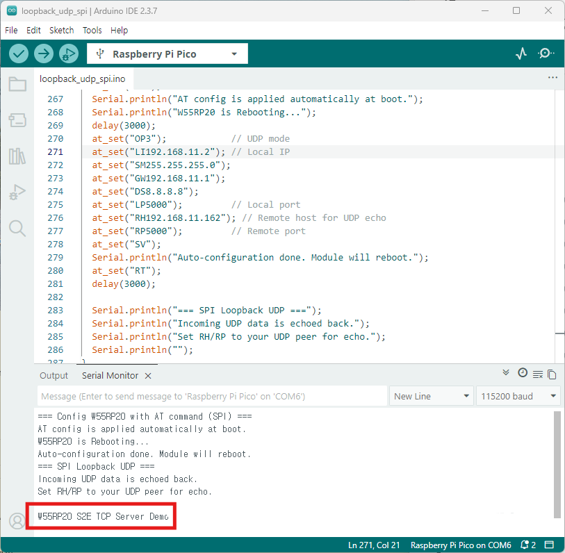
- UDP
void setup() {
...
  at_set("OP3");            // UDP mode
  at_set("LI192.168.11.2"); // Local IP
  at_set("SM255.255.255.0");
  at_set("GW192.168.11.1");
  at_set("DS8.8.8.8");
  at_set("LP5000");         // Local port
  at_set("RH192.168.11.100"); // Remote host for UDP echo
  at_set("RP5000");         // Remote port
  ...
}
3. Click Upload button or press Ctrl+U
4. Wait for upload to complete
5.3 Open Serial Monitor
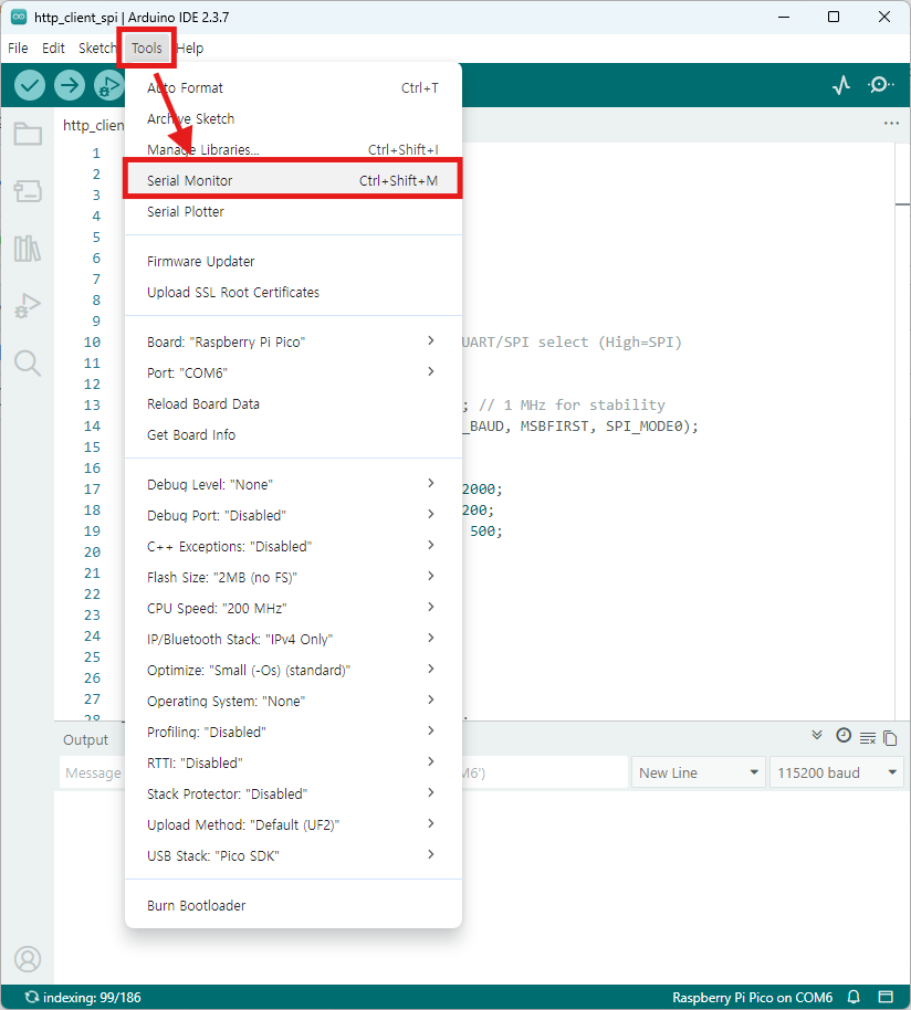
- Go to Tools → Serial Monitor
- Set baud rate to 115200
- Verify network information and connection status
Step 6: Testing with Hercules
TCP Client Test
Hercules Server Setup:
- Launch Hercules
- Select TCP Server tab
- Port: 5000
- Click Listen
- Verify messages from Pico appear
- Type response message and click Send
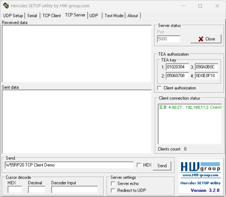
Expected Results:
- Hercules receives "W55RP20 S2E TCP Server Demo" message
- Serial Monitor displays Hercules response
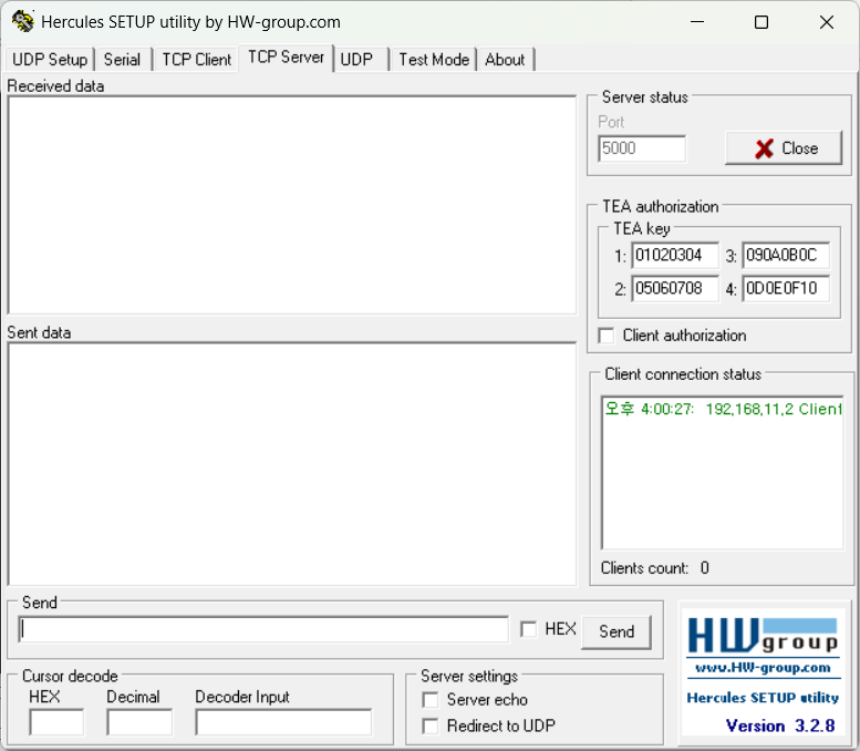
TCP Server Test
Hercules Client Setup:
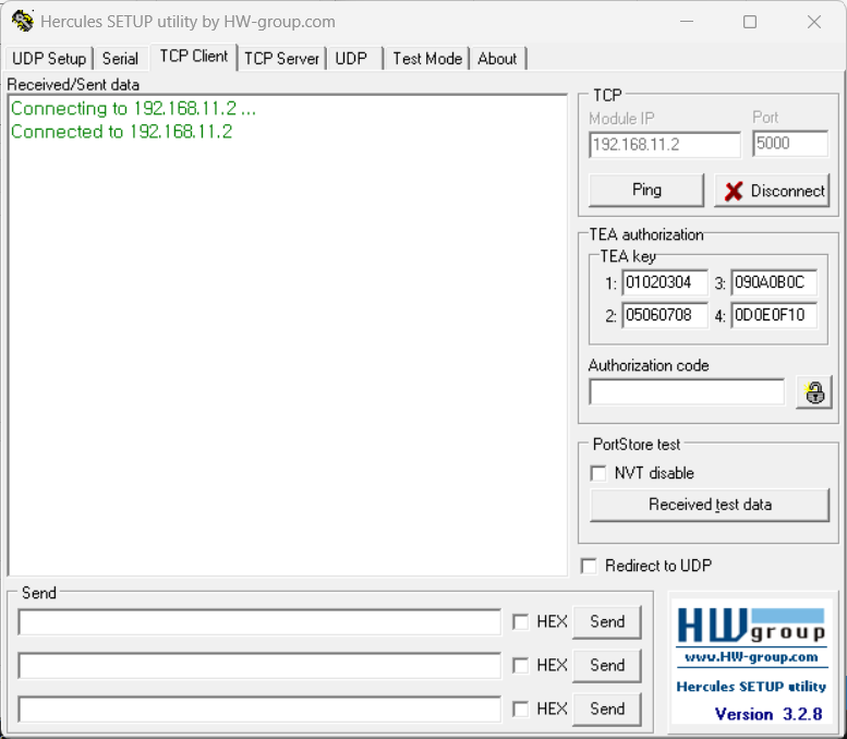
- Launch Hercules
- Select TCP Client tab
- IP: 192.168.11.2 (Pico IP address)
- Port: 5000
- Click Connect
- Type message (e.g., "W55RP20 S2E TCP Server Demo")
- Click Send
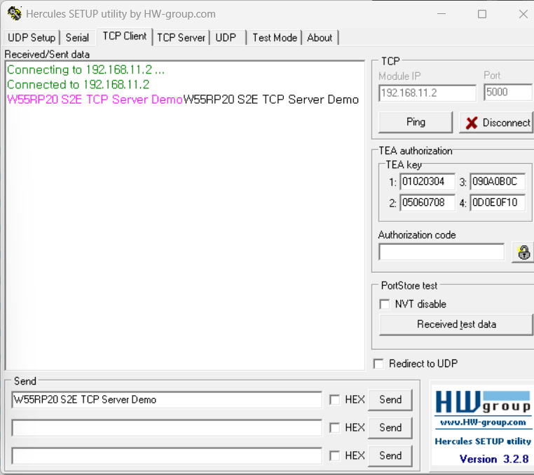
Expected Results:
- Serial Monitor displays "W55RP20 S2E TCP Server Demo"
- Hercules receives echoed message
UDP Test
Hercules UDP Setup:
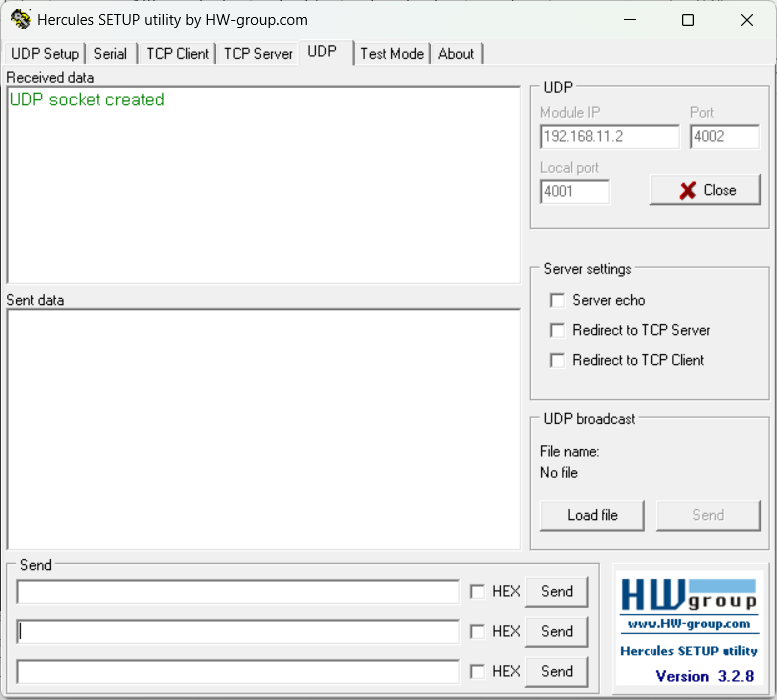
- Launch Hercules
- Select UDP tab
- Module IP: 192.168.11.2
- Module Port: 5000
- Local Port: 5000 (or other available port)
- Type message (e.g., "W55RP20 S2E TCP Server Demo")
- Click Send
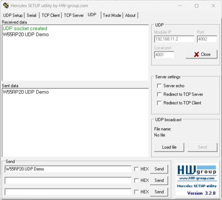
Expected Results:
- Serial Monitor displays "W55RP20 S2E TCP Server Demo"
- Hercules receives echoed packet
-
ioNIC_Arduino_example
