
W55RP20-S2E AT command example (Micropython)
This program is an example that sends AT commands to the W55RP20 S2E board via UART or SPI interface using MicroPython on a Raspberry Pi Pico (Master).
WIZnet - W55RP20
x 1
micropython - MicroPython
x 1
How to AT Command Example (MicroPython)
This program is an example that sends AT commands to the W55RP20 S2E board via UART or SPI interface using MicroPython on a Raspberry Pi Pico (Host). It demonstrates how to configure the module interactively through a shell-like interface.
Step 1: Prepare software
The following software is required to run and test the MicroPython example.
- Thonny : An integrated development environment for MicroPython. used to write, upload, and run code.
- Hercules
Step 2: Prepare hardware
1. Connect GPIO13 according to the selected UART/SPI mode of the W55RP20 EVB Pico, as illustrated below.
| GPIO13 Pin | Desc |
| LOW(GND) | UART mode (default) |
| HIGH(3.3V) | SPI mode |
2. Connect the Raspberry Pi Pico and the W55RP20 EVB Pico using jumper wires as shown below, depending on the selected UART/SPI mode.
- Important Note on Mode Switching: In this example setup, GPIO 13 of the W55RP20 EVB Pico is physically connected to GPIO 13 of the Raspberry Pi Pico. The Host Pico sets the mode (High/Low) automatically based on the software configuration.
- If you change the
MODEin the code (e.g., UART ↔ SPI): You MUST reset both boards (Raspberry Pi Pico and W55RP20 EVB Pico) to ensure the mode is switched and recognized correctly.
If UART mode :
| Raspberry Pi Pico | W55RP20 EVB Pico |
| GPIO4 (UART_TX) | GPIO5 (UART_RX) |
| GPIO5 (UART_RX) | GPIO4 (UART_TX) |
| GPIO13 (MODE_SEL) | GPIO13 (MODE_SEL) |
| GND | GND |
If SPI mode :
| Raspberry Pi Pico(Master) | W55RP20 EVB Pico(Slave) |
| GPIO2 (SPI_CLK) | GPIO2 (SPI_CLK) |
| GPIO3 (SPI_TX) | GPIO4 (SPI_RX) |
| GPIO4 (SPI_RX) | GPIO3 (SPI_TX) |
| GPIO5 (SPI_CS) | GPIO5 (SPI_CS) |
| GPIO26 (SPI_INT) | GPIO26 (SPI_INT) |
| GPIO13 (MODE_SEL) | GPIO13 (MODE_SEL) |
| GND | GND |
3. Connect the Raspberry Pi Pico to your PC (desktop or laptop) using a 5-pin Micro USB cable.
4. Connect the W55RP20 EVB Pico to your PC (desktop or laptop) using a USB Type-C cable.
Step 3: Setup AT Command Example
- Raspberry Pi Pico (Master) : Getting started with Raspberry Pi Pico (MicroPython)
Please refer to the link below to install the MicroPython firmware on the Raspberry Pi Pico.
- W55RP20 EVB Pico : Getting started with W55RP20 EVB Pico
Please refer to the link below for instructions on how to use the W55RP20 S2E.
Step 4: Upload Code
- Raspberry Pi Pico
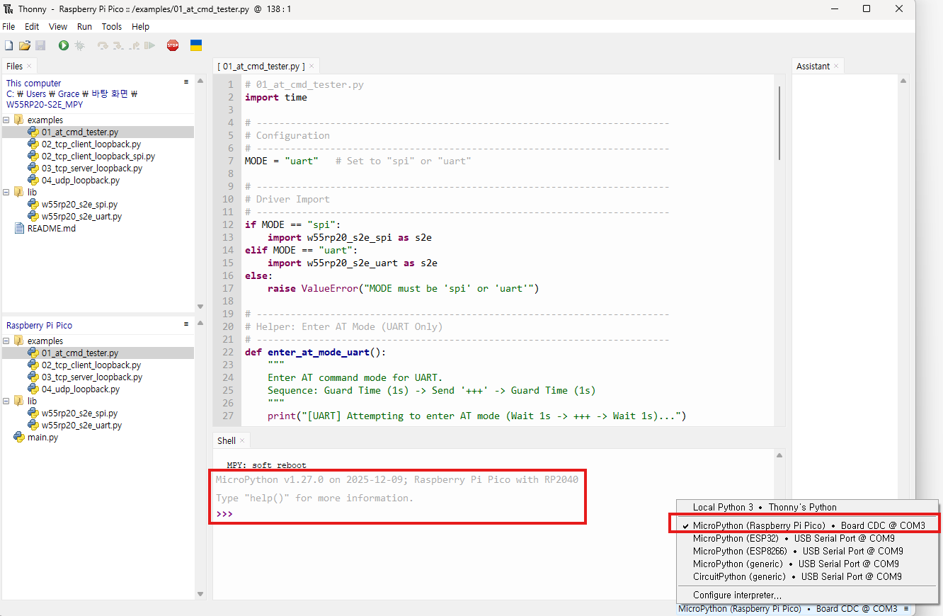
Open Thonny IDE and connect to the Raspberry Pi Pico. Upload the following driver and example files to the Pico's storage.
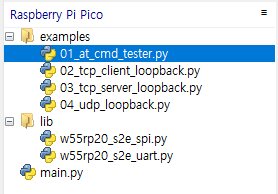
Required Files:
w55rp20_s2e_uart.py(Required for UART mode)w55rp20_s2e_spi.py(Required for SPI mode)01_at_cmd_tester.py(Main example code)
Open 01_at_cmd_tester.py and modify the MODE variable at the top of the code to match your hardware connection.
# Configuration
MODE = "uart" # Set to "spi" or "uart"- W55RP20 EVB Pico
Following Step 3 in the Getting Started Guide, program the W55RP20 EVB Pico with the UF2 file and write the MAC address to complete the setup.
Step 5: Run
For detailed information about the AT commands supported by the W55RP20 S2E, please refer to the document below.
Run the 01_at_cmd_tester.py script in Thonny (press F5). The shell will act as an interactive terminal for sending AT commands.
Step 5.1: UART mode
When the example is successfully running in UART mode, the Host will automatically send +++ to enter AT Command Mode. You will see the following output in the Thonny Shell:
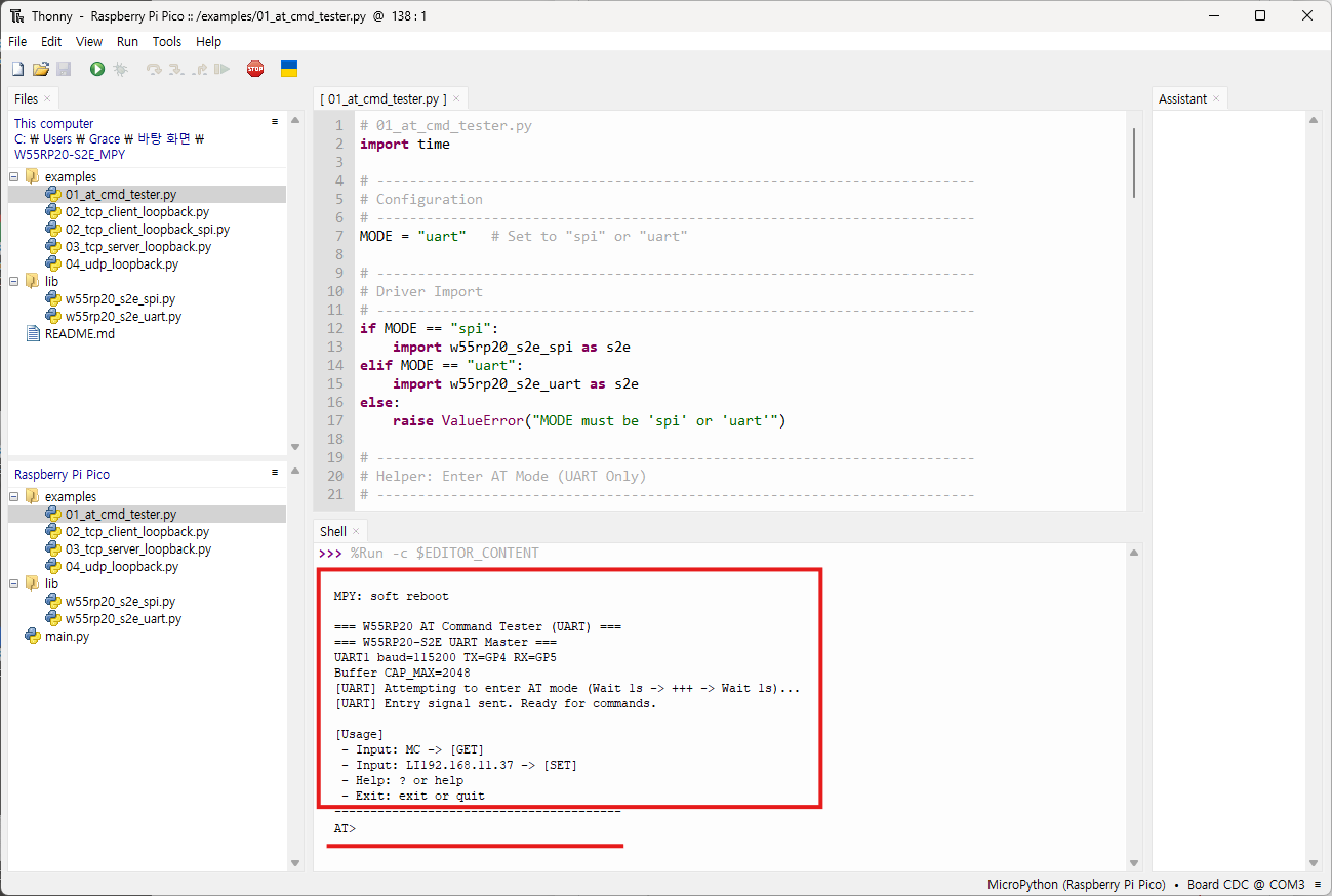
=== W55RP20 AT Command Tester (UART) ===
[UART] Attempting to enter AT mode (Wait 1s -> +++ -> Wait 1s)...
[UART] Entry signal sent. Ready for commands.

[Usage]
 - Input: MC (Parses as CMD='MC', Param='') -> [GET]
 - Input: OP1 (Parses as CMD='OP', Param='1') -> [SET]
 - Help: ? or help
 - Exit: exit or quit
----------------------------------------
AT>
Testing Examples:
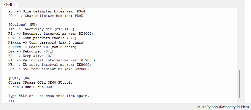
1.Enter HELP or ? to display usage instructions for AT commands.
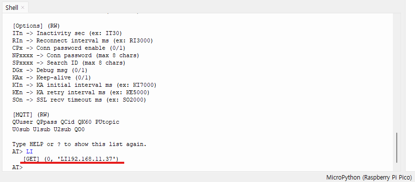
2. Enter the LI command to get the current Local IP address.
3. Enter LI 192.168.11.32 to set a new Local IP address.
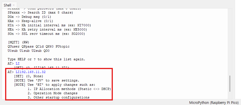
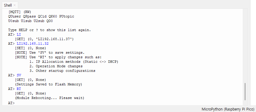
4. Enter the SV command to save the settings to flash memory.
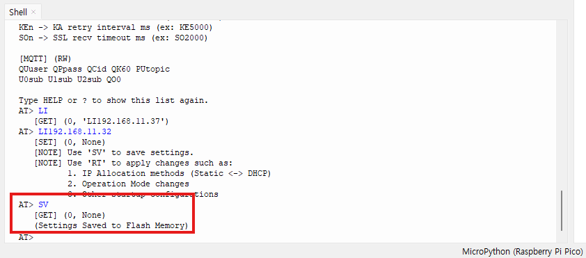
5. Enter the RT command to reboot the module and apply the change
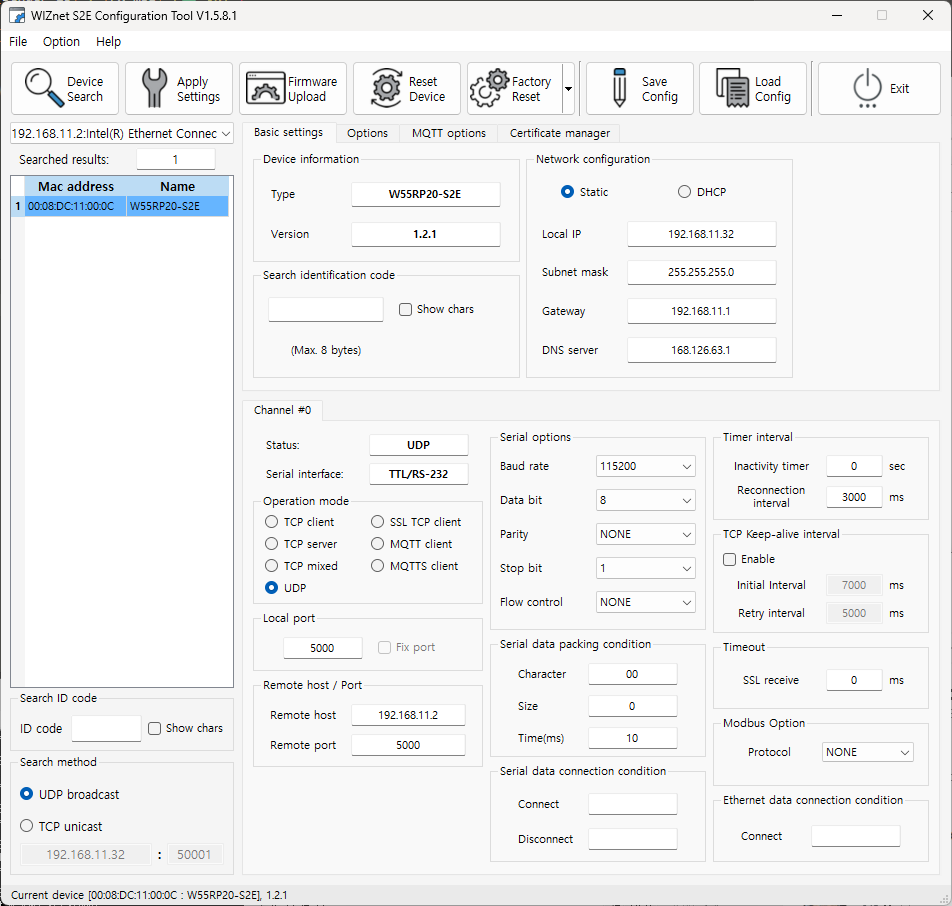
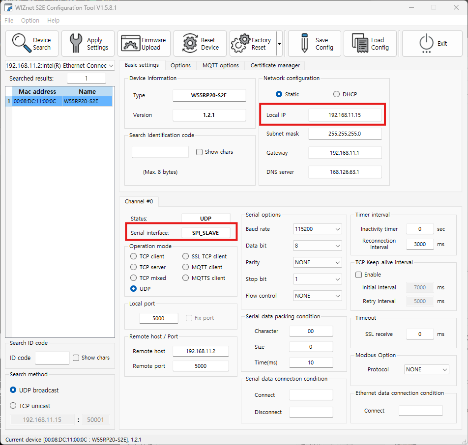
When you perform a search using the WIZnet Config Tool, you can confirm that the Local IP address of the W55RP20 S2E has been changed.
Step 5.2: SPI mode
When running in SPI mode, the example immediately establishes communication.
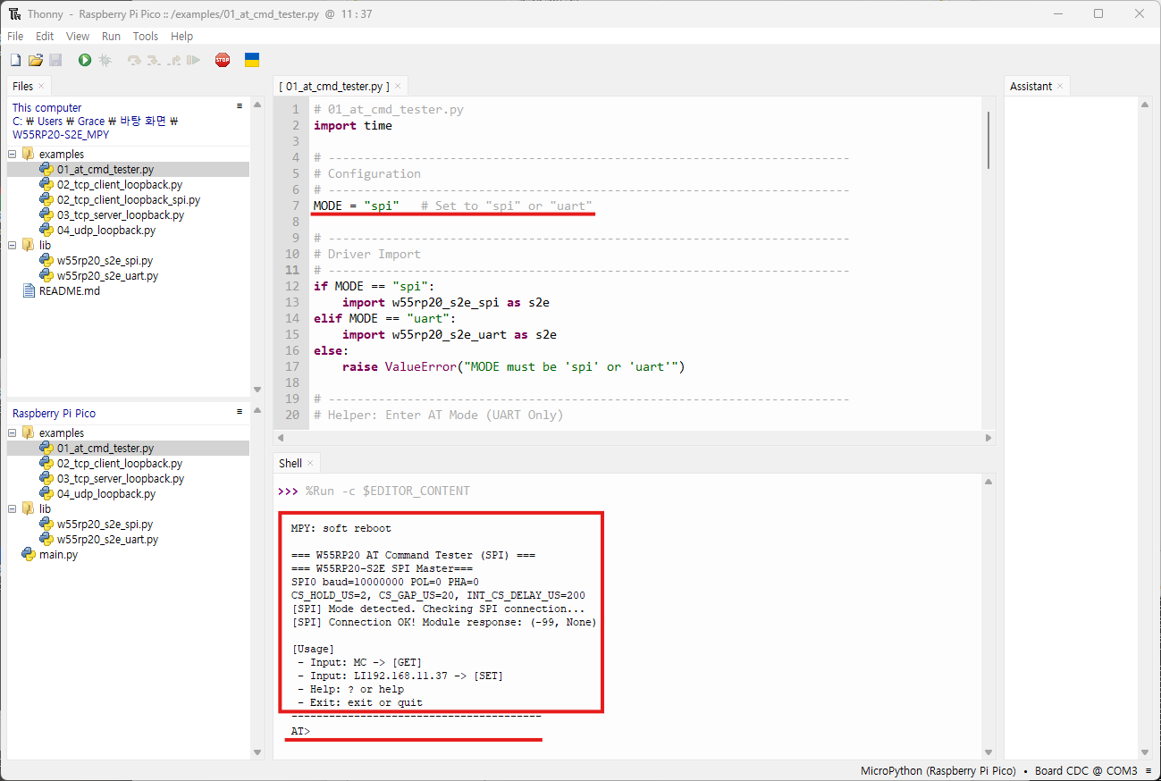
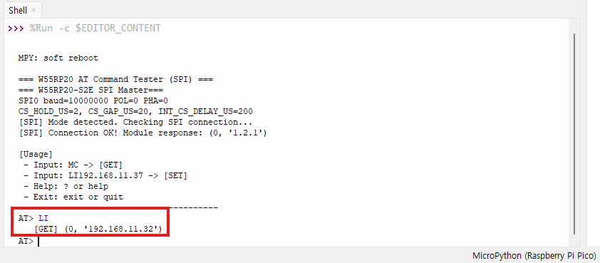
Testing Examples:
1.Enter the LI command to get the current Local IP address.
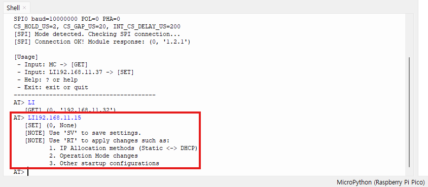
2. Enter LI 192.168.11.15 to set a new Local IP address.
3. Enter SV to save the configuration.
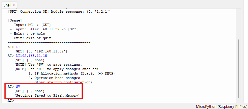
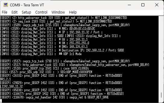
After saving and rebooting, you can verify the new Local IP address (192.168.11.15) by searching for the device using the WIZnet Config Tool.
-
GitHub : W55RP20-S2E_master_Micropython
