ORION_VI_PROPULSION_SYSTEM
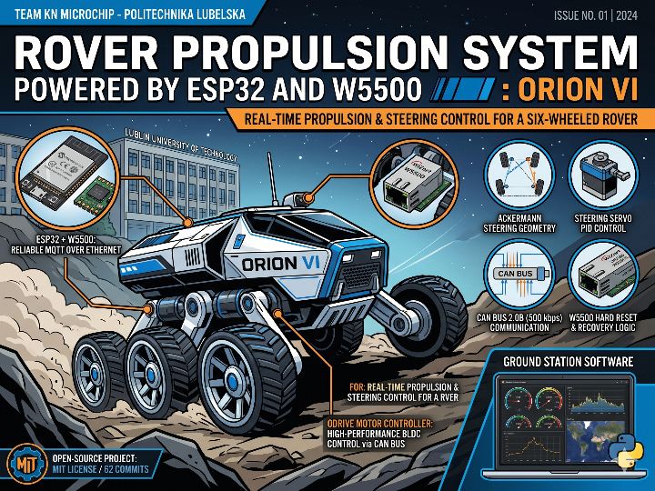
Open-source rover propulsion system using ESP32 + WIZnet W5500, controlling four ODrive motors over CAN bus via MQTT.
Rover Propulsion System Powered by ESP32 and W5500 — ORION VI
In One Sentence
"A propulsion and steering control system for a six-wheeled rover, built by a Polish university engineering team — receiving MQTT commands over ESP32 + W5500 Ethernet and controlling four ODrive motor controllers in real time via CAN bus."
A rover is a wheeled robotic vehicle designed to traverse rough terrain. The concept originates from NASA's planetary exploration missions, and university teams around the world now design and compete with their own rover builds. Events like the European Rover Challenge are a driving force behind projects like this one. ORION VI, developed by team KN Microchip, is a product of that same engineering culture.
One of the trickiest parts of building a remotely operated rover is network communication. Latency means delayed steering; a dropped connection means the rover must stop. The ORION VI Propulsion System addresses this with an ESP32 and WIZnet W5500 Ethernet chip combination — an open-source project that keeps control reliable under field conditions.
KN Microchip is a student engineering team at Politechnika Lubelska (Lublin University of Technology), Poland. The project currently has 62 commits and 2 forks.
Key Concept
What is ODrive? ODrive is an open-source high-performance motor driver for BLDC and brushless servo motors. It receives velocity and position commands over CAN bus and closes the control loop using encoder feedback. It's widely used in robotics, rovers, and CNC systems.
Hardware Setup
The rover's left and right drivetrain each run on an independent ESP32 + W5500 module. Each ESP32 controls two ODrive units (front and rear) over CAN, and handles two steering servos as well.
| Component | Model / Interface | Role |
|---|---|---|
| MCU | ESP32 | Main controller |
| Ethernet | WIZnet W5500 (SPI) | Dedicated MQTT communication |
| Motor drivers | ODrive × 2 (Front / Rear) | BLDC motor velocity control |
| Communication bus | CAN 2.0B (500 kbps) | ESP32 ↔ ODrive |
| Steering | Servo motors × 2 | Independent front and rear steering |
| Sensors | ACS712 (current), ADC (voltage) | Servo health monitoring |
| Ground station software | Python (Tkinter + pygame) | Operator dashboard |
Pin Map (ESP32 ↔ W5500):
| Signal | ESP32 GPIO |
|---|---|
| SPI SCK | GPIO 18 |
| SPI MISO | GPIO 19 |
| SPI MOSI | GPIO 23 |
| CS (Chip Select) | GPIO 5 |
| RESET | GPIO 27 |
System Architecture and Data Flow
Features
MQTT Control Protocol
The operator PC publishes JSON packets to the propulsion/cmd topic at 20 Hz. Each packet carries velocity (RPS) and steering angle (rad) for all four wheels simultaneously.
{
"eventType": "propulsion",
"velocity": {
"fl_speed": 12.5, "rl_speed": 12.5,
"fr_speed": 12.5, "rr_speed": 12.5,
"fl_rad": 0.5, "rl_rad": -0.5,
"fr_rad": 0.5, "rr_rad": -0.5
}
}The ESP32 publishes telemetry in the opposite direction every 100 ms, including per-wheel velocity and position, plus servo current and voltage.
Ackermann Steering Geometry
Rather than applying a simple left/right steering value, the ground station calculates the precise steering angle for each wheel using the Ackermann formula. This ensures the inner and outer wheels turn at different angles through a corner, minimizing slip.
# Calculated in the Python ground station
fl_rad = math.atan((s * L) / (2 + s * W))
fr_rad = math.atan((s * L) / (2 - s * W))
rl_rad = -fl_rad
rr_rad = -fr_radSteering Servo PID Control
Applying abrupt PWM jumps to a high-torque servo can strip the gears. The ESP32 firmware uses a software PID controller to limit the steering rate.
- Maximum steering velocity: 0.5 rad/s (
STEER_MAX_VEL) - Maximum steering angle: ±1.0 rad (
MAX_STEER_RAD) - Anti-windup included (integral clamped to ±1.0 rad)
Safety System
| Layer | Mechanism | Trigger |
|---|---|---|
| MQTT Watchdog | ESP32 internal timer | Full stop if no command for 1000 ms |
| Emergency Brake | L2 + R2 simultaneously | Immediate velocity = 0, ramp mode disabled |
| Connection Recovery | W5500 hard reset after 5 failures | Unstable MQTT connection |
The W5500 reset logic is particularly noteworthy. Rather than simply retrying the MQTT connection, five consecutive failures trigger a call to initNetwork(), which physically resets the W5500 via GPIO 27 (LOW → HIGH) and reinitializes the full Ethernet stack from scratch. This allows network recovery in the field without cutting power.
The Role of WIZnet W5500
The W5500 does more than provide an Ethernet port in this system.
Hardwired TCP/IP stack Network processing is offloaded entirely to the chip, freeing the ESP32 CPU to handle CAN bus traffic, PID computation, and ADC sensor reads in parallel without introducing latency into MQTT communication.
Bidirectional real-time communication Incoming commands (propulsion/cmd) and outgoing telemetry (propulsion/feedback_*) operate simultaneously on the same connection — 20 Hz control commands and 10 Hz telemetry coexisting without interference.
Self-recovery via hard reset
void initNetwork() {
pinMode(ETH_RST_PIN, OUTPUT);
digitalWrite(ETH_RST_PIN, LOW); delay(100);
digitalWrite(ETH_RST_PIN, HIGH); delay(200);
SPI.begin(SPI_SCK_PIN, SPI_MISO_PIN, SPI_MOSI_PIN, ETH_CS_PIN);
Ethernet.init(ETH_CS_PIN);
Ethernet.begin(mac, ip);
// ...
}5 failed MQTT connections → initNetwork() re-called → W5500 physically reset via GPIO → full Ethernet stack reinitialized. Network recovery in the field without a power cycle.
Ground Station Software
A Python-based operator dashboard is included. A separate Steam Deck build (Base_ApplicationSteamDeck) is also available for outdoor field operations.
- Real-time velocity gauge and graph (Matplotlib)
- Per-ODrive monitoring for all four units (RPS, position, servo current, packet age)
- Latency estimator (cross-correlates command publish time with encoder feedback)
- Network status indicators (MQTT broker, rover, ground station TCP health LEDs)
- Joystick / Steam Deck pad / keyboard input support
Extensibility
Splitting the left and right drivetrain into independent ESP32 + W5500 modules makes the architecture easy to scale. The same hardware configuration is reused for both sides — only the CURRENT_SIDE macro in config.h differs between the two builds. The same pattern can be extended to additional modules or adapted to different robot platforms without restructuring the codebase.
Tech Stack Summary
| Component | Details |
|---|---|
| MCU | ESP32 (Xtensa LX6, 240 MHz) |
| Ethernet | WIZnet W5500 (Hardwired TCP/IP, SPI) |
| Firmware language | C++ (Arduino IDE / PlatformIO) |
| Motor driver communication | CAN 2.0B, 500 kbps, ODrive Simple CAN v3.6/v4 |
| Message broker | MQTT (paho, port 1883) |
| Data format | JSON (ArduinoJson) |
| Ground station language | Python 3.10+ |
| Ground station libraries | Tkinter, Matplotlib, paho-mqtt, pygame |
| License | MIT |
FAQ
Q. Both ESP32 modules subscribe to the same MQTT topic — how are commands kept separate? A. The control topic (propulsion/cmd) is shared, but the JSON packet contains per-wheel keys (fl_speed, fr_speed, etc.). The left ESP32 only parses fl_speed, rl_speed, fl_rad, and rl_rad; the right parses the fr_* and rr_* equivalents. Which side a module belongs to is determined at compile time by the CURRENT_SIDE macro in config.h.
Q. How does the system recover when the W5500 connection becomes unstable? A. After five consecutive MQTT connection failures, the firmware calls initNetwork() rather than just retrying the client. This physically resets the W5500 by toggling GPIO 27 LOW then HIGH, and reinitializes the full Ethernet stack from scratch — all without a power cycle.
Q. Can CAN bus and Ethernet run on the same ESP32 simultaneously? A. Yes. The W5500 exclusively uses the SPI bus (GPIO 18/19/23/5), while the CAN transceiver uses separate pins (GPIO 25/26). Because the W5500's hardwired TCP/IP stack handles all network processing at the chip level, the ESP32 CPU remains free for CAN packet handling, PID computation, and ADC reads without contention.
Project Links
- GitHub: https://github.com/knmicrochip/ORION_VI_PROPULSION_SYSTEM
- Team: KN Microchip (Politechnika Lubelska, Poland)
- Commits: 62 / Forks: 2
- License: MIT