
[Recuration] Using Raspberry Pi Pico(W5100S-EVB-Pico) ADC
This basic GPIO input/output testing provides foundational knowledge for using the Raspberry Pi Pico in various electronics projects.
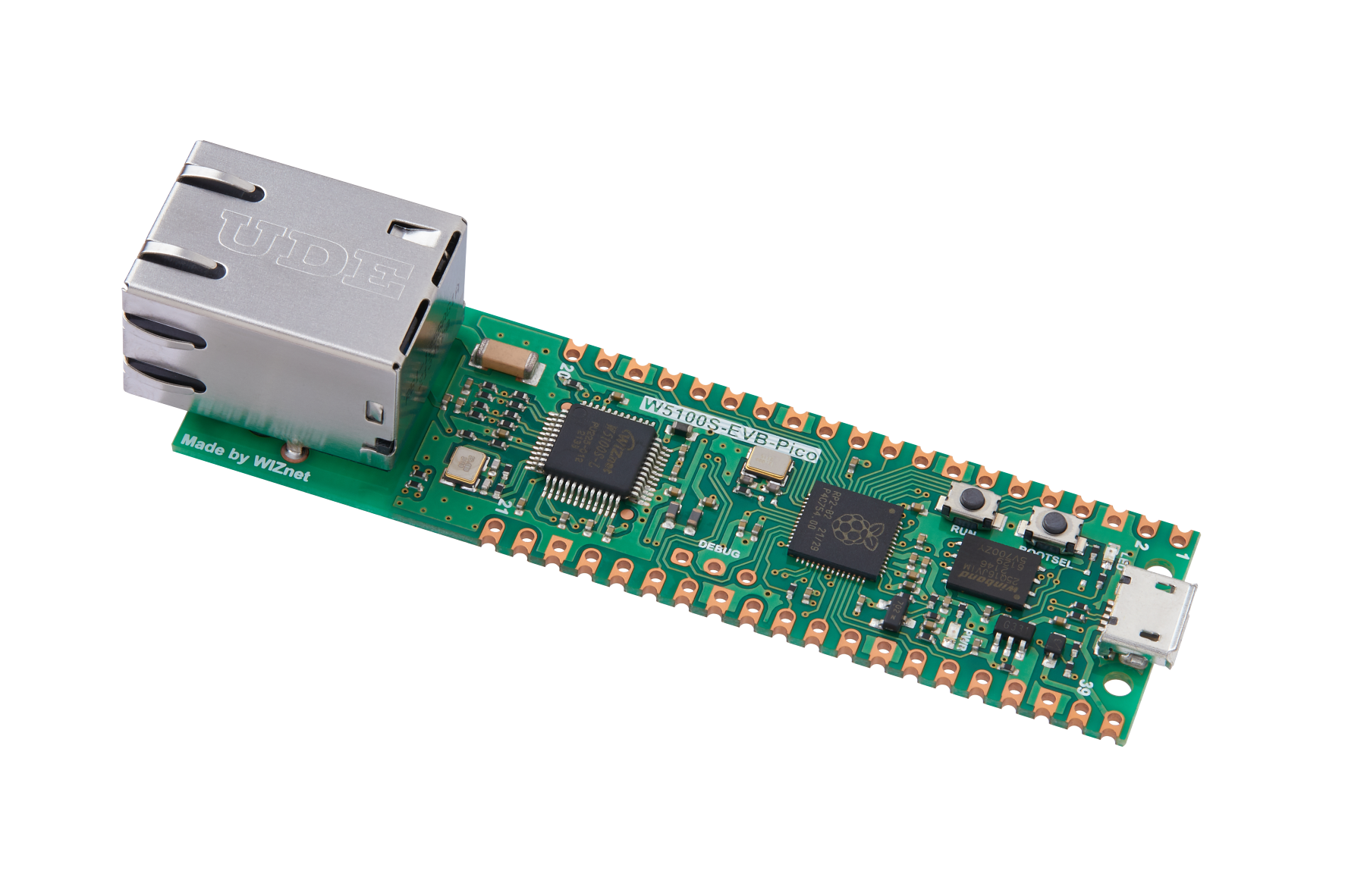
WIZnet - W5100S-EVB-Pico
x 1

Adafruit - Circuitpython
x 1
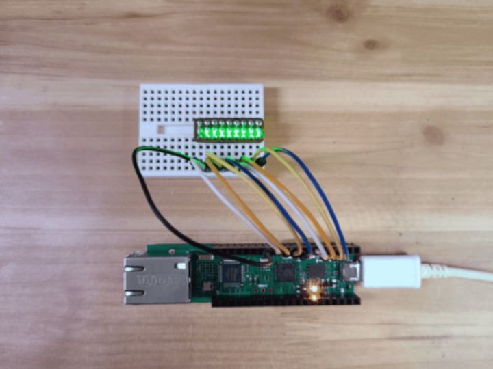
The tests were conducted on a Raspberry Pi Pico with rp2040, using Adafruit CircuitPython 7.2.0. For easy connection to a breadboard and jumper wires, pin headers were soldered on the top side of the Raspberry Pi Pico. While this arrangement makes accessing the BOOTSEL button slightly inconvenient, it's not a significant issue as firmware updates are infrequent.
For GPIO output testing, an LED that can be connected to 8 ports was used. Each pin of this LED was connected to the GP2 to GP9 ports on the Raspberry Pi Pico board, and the last GND was connected together. The following code was written to test the GPIO output by setting each port as an output port and toggling the LEDs ON and OFF at 0.5-second intervals:
import board
import digitalio as io
import time

LEDs = []
LEDpin = [board.GP2, board.GP3, board.GP4, board.GP5,
          board.GP6, board.GP7, board.GP8, board.GP9]

for i in range(len(LEDpin)):
    led = io.DigitalInOut(LEDpin[i])
    led.direction = io.Direction.OUTPUT
    LEDs.append(led)

while True:
    for l in LEDs:
        l.value = True
    time.sleep(0.5)
    for l in LEDs:
        l.value = False
    time.sleep(0.5)
When this code is saved as code.py and executed in the Thonny IDE, all 8 LEDs simultaneously toggle ON and OFF.
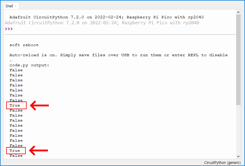
Next, a GPIO input test was performed. For this, one side of a switch was connected to +3.3V and the other side to the GP2 port. The default state of the switch is set to False due to the Pull.DOWN configuration. When pressed, the switch connects to +3.3V, resulting in a High state, or True output. To minimize frequent print outputs, sleep was used. The code used for this test is as follows:
import time
import board
import digitalio

button = digitalio.DigitalInOut(board.GP2)
button.switch_to_input(pull=digitalio.Pull.DOWN)

while True:
    print(button.value)
    time.sleep(0.5)
Running this code in Tonny as code.py results in the display of True when the switch is pressed and False as the default state when it is released.
This basic GPIO input/output testing provides foundational knowledge for using the Raspberry Pi Pico in various electronics projects.